Transcription
Introduction to Short CircuitCurrent CalculationsCourse No: E08-005Credit: 8 PDHVelimir Lackovic, Char. Eng.Continuing Education and Development, Inc.22 Stonewall CourtWoodcliff Lake, NJ 07677P: (877) 322-5800info@cedengineering.com
Introduction to Short Circuit Current CalculationsIntroduction and ScopeShort circuits cannot always be prevented so system designers can only try tomitigate their potentially damaging effects. An electrical system should be designedso that the occurrence of the short circuit becomes minimal. In the case short circuitoccurs, mitigating its effects consists of:-Isolating the smallest possible portion of the system around the faulted area inorder to retain service to the rest of the system, and-Managing the magnitude of the undesirable fault currents.One of the major parts of system protection is orientated towards short-circuitdetection. Interrupting equipment at all voltage levels that is capable of withstandingthe fault currents and isolating the faulted area requires considerable investments.Therefore, the main reasons for performing short-circuit studies are as follows:-Defining system protective device settings and that is done by quantities thatdescribe the system under fault conditions.-Verification of the adequacy of existing interrupting equipment.-Assessment of the effect that different kinds of short circuits of varyingseverity may have on the overall system voltage profile. These calculationsidentify areas in the system for which faults can result in unacceptable voltagedepressions.-Defining effects of the fault currents on various system components such ascables, overhead lines, buses, transformers, capacitor banks and reactorsduring the time the fault persists. Mechanical stresses from the resulting faultcurrents are compared with the corresponding short-term withstandcapabilities of the system equipment.-Compliance with codes and regulations governing system design andoperation.-Design and sizing of system layout, neutral grounding, and substationgrounding.
Electrical power systems are systems composed of a wide range of powerequipment used for generating, transmitting, and distributing electrical power toconsumers. Complexity of these systems indicates that breakdowns and faults areunavoidable, no matter how carefully these systems have been designed. Anelectrical system can be designed with zero failure rate, however that iseconomically unjustifiable. From the perspective of short-circuit analysis, systemfaults manifest themselves as insulation breakdowns. These breakdowns lead to oneor more phenomena:-Currents of excessive magnitudes that usually cause equipment damage-Undesirable power flow-Voltage depressions-Excessive over-voltages-Cause conditions that could harm personnelExtent and requirements of short-circuit studiesShort circuit studies are as necessary for any power system as other fundamentalsystem studies such as power flow studies, transient stability studies, harmonicanalysis studies, etc. Short-circuit studies can be performed at the planning stage inorder to help finalize the single line diagrams, determine and set voltage levels, andnetwork equipment such as cables, transformers, and conductors. For existingsystems, fault studies are necessary in the cases of added generation, installation ofextra rotating loads, network topology modifications, rearrangement of protectionequipment, verification of the adequacy of existing breakers, relocation of alreadyacquired switchgear, etc. Short-circuit studies can also be performed in order toduplicate the reasons and system conditions that led to the system’s failure.The requirements of a short-circuit study will depend on the set objectives. Theseobjectives will dictate what type of short-circuit analysis is required. The amount ofdata required will also depend on the extent and the nature of the study. The majorityof short-circuit studies in industrial and commercial power systems address one ormore of the following four kinds of short circuits:
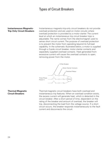
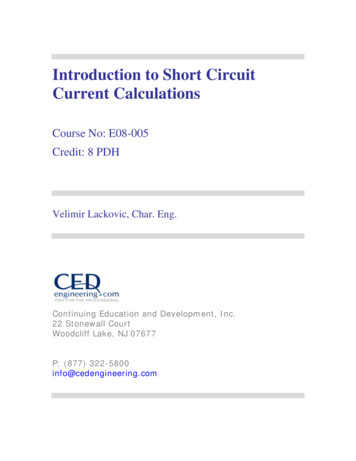
-Line-to-line fault. Any two phases shorted together.-Double line-to-ground fault. Any two phases connected together and then toground.-Single line-to-ground fault. Any one, but only one, phase shorted to ground.-Three-phase fault. May or may not involve ground. All three phases shortedtogether.Fault types are graphically presented in the figures below:L3L3L2L2L1L1Three Phase FaultLine to Line FaultL3L3L2L2L1L1Double Line toGround FaultSingle Line-to-Ground FaultThese types of short circuits are also referred to as “shunt faults,” since all four areassociated with fault currents and MVA flows diverted to paths different from the prefault “series” ones. Three-phase short circuits often turn out to be the most severe ofall. It is thus customary to perform only three phase-fault simulations when searchingfor the maximum possible magnitudes of fault currents. However, exceptions exist.For instance, single line-to-ground short-circuit currents can exceed three-phaseshort-circuit current levels when they occur in the electrical vicinity of:-The solidly grounded wye side of a delta-wye transformer of the three-phasecore (three-leg) design-The grounded wye side of a delta-wye autotransformer
-A solidly grounded synchronous machine-The grounded wye, grounded wye, delta-tertiary, three-winding transformerFor electrical systems where any or more of the above conditions exist, it isadvisable to perform a single line-to-ground fault simulation. Line-to-line or doubleline-to-ground fault studies may also be required for protective device coordinationrequirements. Also, since only one phase of the line-to-ground fault can experiencehigher interrupting requirements, the three-phase fault will still contain more energybecause all three phases will need the same interrupting requirements. Other typesof fault conditions that may be of interest include the “series faults” and they refer toone of the following types of system unbalances:-Two lines open. Any two of the three phases may be open.-One line open. Any one of the three phases may be open.-Unequal impedances. Unbalanced line impedance discontinuity.Series fault types are graphically presented in the figures below:L3L3L2L2L1L1One line openTwo lines openThe term “series faults” is used because these faults are associated with aredistribution of the pre-fault load current. Series faults are of interest whenassessing the effects of snapped overhead phase wires, failures of cable joints,blown fuses, failure of breakers to open all poles, inadvertent breaker energizationacross one or two poles and other situations that result in the flow of unbalancedcurrents.
System modelling and computational techniquesAC and DC decrementPhysical phenomena that determine the magnitude and duration of the short-circuitcurrents are:-The operation of the rotating machinery in the electrical system-The electrical proximity of the rotating machinery to the short-circuit location-The fact that the pre-fault system currents cannot change instantaneously,due to the significant system inductanceThe first two can be conceptually linked to the AC decrement, while the third, to theDC decrement.AC decrement and rotating machineryFor modelling purposes, these impedances increase in magnitude from the minimumpost fault subtransient value 𝑋𝑑" , to the relatively higher transient value 𝑋𝑑′ , andfinally reach the even higher steady-state value 𝑋𝑑 , assuming that the fault is notcleared before. The rate of increase of machine reactance is different forsynchronous generators/motors and induction motors. Rate of increase for inductionmotors is higher than for synchronous generators. This modelling approach isfundamental in properly determining the symmetrical RMS values of the short-circuitcurrents furnished by the rotating equipment for a short circuit anywhere in thesystem.AC decrement is determined by the fact that the magnetic flux inside the windings ofthe rotating machinery cannot change momentarily. For that reason, synchronousmachines, under fault conditions, show different flux variation patterns as comparedto induction machines. The flux dynamics dictate that a short-circuit current decayswith time until a steady-state value is reached. Machine software models presentrotating machines as constant voltages behind time-varying impedances.
Fault current DC decrement and system impedancesShort circuit currents cleared by circuit breakers must consider this unidirectionalcomponent, especially for shorter interrupting periods. Same DC component isimportant when verifying the capability of a circuit breaker to reclose against orwithstand fault currents. Fault currents containing high current DC offsets, usuallypresent no zero crossings in the first several cycles right after fault introduction andare especially burdensome to the circuit breakers of large generators.Fault current DC decrement is also impacted by the fact that because the currentexisting in the system before the fault, cannot change instantaneously, aconsiderable unidirectional component may exist in the fault current which actuallydepends on the exact occurrence of the short circuit. This unidirectional componentof the fault current is often referred to as DC current offset as it reduces with timeexponentially. The rate of decay is related to the system total reactance andresistance. Although this decay is quick, the DC current component could lastenough time to be detected by the protective relay equipment, particularly when fastfault clearing is very needed to maintain system stability or prevent the damagingeffects of the fault currents.Modelling requirements of the power systemFault currents have dynamic aspect that is necessary to associate calculated shortcircuit currents to a specific moment in time from the onset of the short circuit. ACcurrent decrement assessment is used to properly determine the symmetrical RMSvalues of the short circuit currents, while DC decrement calculations provide thenecessary DC current component of the fault current, hence affording a correctapproximation of the total short circuit current. The total fault current, must be usedfor breaker and switchgear sizing and in some specific scenarios for protective relaydevice coordination. Electrical system topology conditions are evenly significantbecause the system arrangement and electrical closeness of the rotating machineryto the fault location will influence the total order of magnitude of the fault current. It is
therefore essential to come up with an electrical system model as a whole andexamine it in an accurate and computationally convenient manner.Modern power systems are usually compromised of multiple generators and motors.They are interlinked using other equipment like transformers, overhead lines andcables. Also there is usually one or more locations at which a local, smaller powersystem is connected to a larger electrical grid. These locations are referred to as“point of common coupling”. The main goal of the short-circuit study is to calculatethe short-circuit currents and voltages at various locations throughout the system.Representation of the three-phase vs. symmetrical componentsIt is a customary practice for conventional three-phase electrical systems to beinterpreted on a single-phase basis. Mentioned simplification, successfully appliedfor power flow and transient stability studies, leans on the assumption that theelectrical system is equally balanced or can be accepted to be so for practicalpurposes. However, electrical system modelling, on a single-phase basis isinsufficient for examining processes that take into account serious systemimbalances. From the short-circuit analysis point of view, three-phase fault lendsitself to single-phase analysis, because the fault is balanced and asks for all threephases, presuming a balanced three-phase electrical system. Other short circuitcurrent conditions will bring in imbalances that need the analysis of the remainingunaffected two phases. There are two options to address this problem:-Representation using symmetrical components. Analysis using symmetricalcomponents is a method that, instead of asking for assessment of theimbalanced electrical system, provides provision for the creation of threeelectrical subsystems: the positive, the negative, and the zero-sequence systems that are correctly connected at the short circuit point which depends onthe type of the electrical system imbalance. Once fault currents and voltagesare modelled anywhere in the network, they can be obtained by properlyaggregating findings of the analysis of the three-sequence networks.
-Representation of the system using all three-phases. If the system isrepresented on a three-phase basis, the identity of all three phases isretained. The advantage of this approach is that any kind of short circuitcurrent imbalance can be promptly assessed, including coincidental faults.Moreover, the short circuit current condition is defined with bigger flexibility,especially for arcing faults. The main disadvantages of the technique are:o If the computer program is used, it can be data-intensive.o It is not convenient for manual calculations, even for small electricalsystems.The distinguishable advantage of the approach that uses symmetricalcomponents is that it gives provision for representing imbalanced short circuitconditions, while it still holds the conceptual simplicity of the single-phaseassessment. Additional significant advantage of the symmetrical componentstechnique is that impedances of the system equipment can be measured inthe symmetrical components reference frame.This reduction is true only if the system is balanced in all three phases(excluding fault location which becomes the connection point of the sequencenetworks), the premise that can be entertained without bringing inconsiderable modelling errors for most electrical systems.The main weakness of the method is that for complex short circuit currentconditions, it may bring in more problems than it resolves. The method ofsymmetrical components continues the favoured analytical tool for shortcircuit current analysis for hand and computer-based assessments.Impedances of the electrical system and analysis of symmetrical componentsTheory of the symmetrical components prescribes that for a three-phase electricalsystem, it needs to be established for the assessment of imbalanced short circuitcurrent conditions. The first part is the positive sequence system, that is determined
by a balanced set of voltages and currents of equal magnitude, following the phasesequence of a, b, and c.The second part is the negative sequence system, that is similar to the positivesequence system, but is determined by a balanced set of voltages and currents witha reverse phase sequence of a, c, and b.Lastly, the zero sequence system is defined by a group of voltages and currents thatare in phase with each other and not displaced by 120 degrees, as it is the case withthe other two systems. Electrical connectivity of the zero sequence system can bedifferent from the positive and negative sequence systems. This is due to the factthat it is influenced by the power transformer winding connections and systemneutral grounding; components that are not important when ascertaining thetopology of the positive and the negative sequence networks.Three-phase fault analysis for the balanced systems requires only the positivesequence system components impedances Z 1 (R 1 jX 1 ). For calculation of theline-to-line faults, negative sequence impedances Z 2 (R 2 jX 2 ) are required. Forall faults involving connection to the ground, such as line-to-ground and double lineto-ground faults, the zero sequence system impedances Z 0 (R 0 jX 0 ) are requiredin addition to the positive and negative systems. System neutral groundingequipment components such as grounding resistors or reactors and groundingtransformers constitute an inherent part of the impedance data for the zero sequencesystem.Fault current AC decrement conditions prescribe that rotating electrical equipmentimpedances differ from the onset of the short circuit. This is applicable only topositive sequence impedances that range from sub-transient through transient tosteady-state values. The negative and zero sequence impedances for the rotatingelectrical equipment are considered unaltered. The same is valid for the electricalimpedances of the static system components.Electrical system equipment components such as transformers, overhead lines,cables, bus bars, and static loads, under balanced system conditions can be
considered as static and have the same impedances that are used for calculatingpositive and negative sequence currents. In principle, same components presentdifferent electrical impedances for determining the flow of zero sequence currents.Rotating electrical equipment like electrical synchronous generators and motorshave different electrical impedances for all three phase sequence networks. Thepositive sequence electrical impedances are usually used for balanced power flowcalculations. Sequence impedances must be calculated, measured, specified by themanufacturers of the equipment, or estimated based on the standard engineeringpractice. The zero sequence electrical impedance may not exist for particularrotating equipment which depends on the machine grounding system.Quasi-steady-state short circuit current assessmentQuasi-steady-state short circuit current assessment relates to methods that interpretthe system at steady state. Phasor vectors are used to present voltages across thesystem, currents, and electrical impedances at basic, fundamental frequency.Electrical system modelling and the resulting calculation methods are based on thepremise that the electrical system and its associated electrical components can becomprised of linear models. Keeping electrical system linearity greatly simplifies thecalculations. Moreover, linear algebra and the numerical advancements in matrixcalculations make it possible to enforce practical computer solutions for largeelectrical systems. These methods have been preferred by the many industrystandards.Time domain short circuit current analysis – Calculation methodsTime-domain short circuit current assessment refers to methods that give provisionfor the computation of the fault currents as a function of time from the instant of thefault origin. For large electric power systems, which consist of numerous electricalmachines and generators that jointly contribute to the total fault current, thecontributions of many electrical machines will have to be considered concurrently.Electrical machine models were formulated that let predictions of significant accuracybe made with respect to behaviour of any electrical machine for a short circuitcurrent occurrence either at or beyond its terminals. These models are complex
because they represent in detail not only the electrical machine itself but alsononlinear controllers including excitation systems and their related stabilizationelectronic equipment with associated nonlinearities. It can therefore be noted that thecomputational necessities could be colossal, because the task is cut down tosimultaneously solving a huge number of differential equations. Despite itsunderlying power, the usage of time-domain short circuit current analysis is notwidespread and is only utilized for special calculations because it is data and timeintensive (required data can be at least as requiring as transient stability studies) andit asks for a special software.Industry standards for short circuit current calculationsCertain analytical techniques are defined by industry standards that adhere tospecific guidelines and are specifically accommodated to address the problems ofAC and DC current decay in practical multi-machine systems that are in conformitywith established, practices accepted by the power industry. They are also associatedto and accord with adopted, existing switchgear rating structures. Typical industrystandards are:-International standard, IEC 60909-North American ANSIThe analytical and calculation framework in the analytical processes prescribed bythe aforementioned standards stays algebraic and linear, and the computations arekept easily managed by hand for small systems. The extent of the information basenecessities for computerized solutions is kept to a necessary maximum for thesolutions to be acceptably precise. This type of analyses presents the bestcompromise between solution accuracy and simplicity of the simulation. The vastmajority of commercial fault analysis programs fall under this category.IEC 60909 - International standardStandard IEC 60909 (published in 1988) distinguishes four duty types resulting in
four different calculated short circuit currents:-The initial short-circuit current I" k-The peak short-circuit current I p-The breaking short-circuit current I b-The steady-state fault current I kAlthough, the breaking and steady-state short circuit currents are in principal similarto the interrupting and time-delayed short circuit currents, respectively, the peakshort circuit currents are the maximum fault currents reached during the first cyclefrom a beginning of a fault’s and are importantly different from the first-cycle faultcurrents described in IEEE standards, which are total asymmetrical RMS short circuitcurrents. The initial short-circuit current is determined as the symmetrical RMS shortcircuit current would inflow to the point of the fault if there are no changes in networkimpedances.AC current decrement is addressed by considering contribution from everygeneration source, which depends on the voltage at generator terminals during theshort circuit. AC decrement of induction motor is represented in a different way fromsynchronous machines decrement, because an extra decrement factor thatrepresents the more rapid flux decay is included in induction motors. AC decrementis considered and modelled only when breaking currents are calculated.DC current decrement is addressed in IEC 60909, by using the principle ofsuperposition for the contributing electrical sources in conjunction with topology ofthe network and the locations of the contributing sources with respect to the locationof the fault. Standard IEC 60909 prescribes that different calculation steps need tobe used when the contribution converges to a fault location via a meshed or radialpath. These conditions are applicable to the calculation of peak and asymmetricalbreaking short circuit currents.Standard IEC 60909 gives calculation methodology of the maximum and minimumshort circuit currents. Maximum short circuit currents are used for sizing circuitbreakers while minimum short circuit currents are used for setting protective relays.The main factor for the calculation of the short circuit currents is pre-fault voltage at
the point of the fault and the number of generators in service.Short circuit currents calculated for the steady state take into account the fact thatthe short circuit currents do not contain DC component and that all short circuitcurrent contributions from induction motors have decayed to zero. Synchronousmotors also have to be taken into account. Provisions are taken for salient and roundrotor synchronous machines and for different excitation system settings.Loading conditions before the fault are considered with due attention in IEC 60909.In order to account for system loads leading to higher voltages before the fault, thestandard advocates that voltages before the fault at the fault location point can bedifferent from 1.00 per unit. This means that a load flow solution is not required inorder to calculate short circuit currents. IEC 60909 suggests impedance correctionfactors for the generators. These correction factors can also be applicable to theirstep up transformers.ANSI standards – North American standardIEEE standards covering short circuit current calculations for low voltage electricalsystems (below 1000 V), are:-IEEE Standard 242-1986-IEEE Standard 241-1990-IEEE Standard C37.13-1990-IEEE Standard 141-1993IEEE standards dealing with short circuit current calculations for medium and highvoltage electrical networks are:-IEEE Standard 141-1993-IEEE Standard C37.5-1979-IEEE Standard 241-1990-IEEE Standard 242-1986.-IEEE Standard C37.010-1979
Three types of fault currents are determined, depending on the time frame of interestconsidered from the origin of the fault, as first-cycle fault currents, also calledmomentary fault currents, are the currents at 1/2 cycle after fault initiation. Thesecurrents pertain to the duty circuit breakers face when “closing against” orwithstanding fault currents. These currents usually contain DC offset and arecomputed on the assumption of no AC decay in the contributing sources. Bearing inmind that low voltage circuit breakers operate in the first cycle, their breaking ratingsare compared to these currents.Differences between the IEEE C37 and IEC 60909There are numerous and significant differences between IEEE C37 and IEC 60909short circuit calculation standards. System modelling and computational techniquesare different in the two standards. Because of this results obtained by IEEE and IECstandards can be different, with IEC 60909 generally providing higher short circuitcurrent values. The essential differences between IEEE and IEC short circuitcalculation standards can be summarized as follows:-Short circuit DC current decrement described in IEC 60909 does not alwaysrely on a single X/R ratio. Generally, more than one X/R ratio has to be takeninto account. In addition, the notion of separate X and R networks forobtaining the X/R ratio at the location of the fault is not applicable to IEC60909.-Short circuit AC current decrement considered by IEC 60909 depends on thefault location and the standard quantifies rotating machinery’s proximity to thefault. IEEE standard recommends system-wide modelling of the ACdecrement.-Steady-state short circuit current calculation in IEC 60909 considers excitationsettings of the synchronous machines.Considering these important differences, numerical simulations performed usingIEEE C37 standards cannot be used to account for the computational requirementsof IEC 60909 and vice versa.
Calculated short-circuit currents and interrupting equipmentPreviously discussed calculation procedures are used to perform fault calculationson industrial and commercial power systems that are comprised of several voltagelevels including low, medium and high voltage systems. Fault currents that appear inthe first cycles of the faults are usually used to determine interrupting requirementsof low voltage fuses and breakers. These fault currents are used for the calculationof the:-First cycle currents-Time delayed currents-Interrupting currentsCurrents that are the result of short circuit current calculations are used for mediumand high voltage systems since they operate with a time delay that is introduced byprotective relaying and operating requirements. Since IEEE Standard C37.13-1990has adopted the symmetrical rating structure and calculates symmetrical RMS, faultcurrents and X/R ratio can be considered as sufficient in the case calculated X/Rratio is less than the X/R ratio of the test circuit of the circuit breaker. This procedureis suitable for calculations in systems with a low voltage fuse and circuit breakers asdefined by IEEE Standard C37.13-1990.IEEE Standard C37.010-1979 and IEEE Standard C37.5-1979 contain coefficientsthat can be applied to symmetrical RMS short circuit currents in order to getasymmetrical RMS currents. IEEE Standard C37.5-1979 defines them as totalasymmetrical short circuit currents while IEEE Standard C37.010-1979 describesfault currents that are compared against circuit breaker interrupting capabilities. Theabove mentioned coefficients are obtained from curves normalized against the circuitbreaker contact opening time. In order to be in line with IEC standards, ANSIC37.06-1987 introduced peak fault current to the preferred ratings as an alternativeto total asymmetrical currents.It is important to mention that distinction needs to be made between ratings of
medium and high voltage circuit breakers. Circuits breakers that are described inIEEE Standard C37.5-1979 and that are based on the older rating structure, areassessed on the total asymmetrical short circuit current, or total fault MVA, and shortcircuit current calculations are bounded by minimum parting time. The newer circuitbreaker rating structure that was introduced by IEEE Standard C37.0101979, definesbreakers on their symmetrical basis. The symmetrical short circuit currentscalculated using this method can be sufficient since certain degree of asymmetry isincluded in the rating structure of the breaker depending on the actual operationalconditions and overall system X/R ratio.Remote contribution is defined in IEEE Standard C37.010-1979, IEEE StandardC37.5-1979, IEEE Standard 141-1993 and IEEE Standard 242-1986 as the currentis produced by a generator that:-Has a per unit X"d that is 1.5 times less than the per unit external reactanceon a common MVA base, and-Is located two or more transformations away from the point of the fault.Generally, it needs to be pointed out that the most important step in the calculationsof the total fault currents for the medium and high voltage circuit breakers is decidingwhich part of the total short circuit current comes from “local” and “remote” sourcesin order to obtain a meaningful estimate of the circuit breaker interruptingrequirements. This distinction is reasoned by the fact that currents from remotesources introduce slower AC current decay or do not introduce it comparing to shortcircuit currents from the local sources.Factors that affect short-circuit studies resultsThe accuracy of the calculated short circuit cu
Current Calculations . Course No: E08-005 . Credit: 8 PDH . Velimir Lackovic, Char. Eng. info@cedengineering.com. Continuing Education and Development, Inc. . - The solidly grounded wye side of a deltawye transformer of the three- phase - core (three-leg) design - The grounded wye side of a delta-wye autotransformer . L3 L2 L1 L2 L1 L3 L3 L1