Transcription
EmbeddedDNA PC/104 CPU ModuleAn0029Notes on the use of the SSDand ATA / ATAPI interfacesRev. 1.1Apr 2005COPYRIGHT 1994-2005 Eurotech S.p.A. All Rights Reserved.
2Application NoteABOUT THIS MANUALThis application note contains information about the SSD and ATA / ATAPI interfaces.Via J. Linussio 133020 AMARO (UD)ITALYPhone: 39 0433 485 411Fax: 39 0433 485 499Web: http://www.eurotech.ite-mail: mailto:sales@eurotech.itNOTICEAlthough all the information contained herein has been carefully verified, Eurotech S.p.A. assumes noresponsibility for errors that might appear in this document, or for damage to property or personsresulting from an improper use of this manual and of the related software. Eurotech S.p.A. reserves theright to change the contents and form of this document, as well as the features and specifications of itsproducts at any time, without notice.Trademarks and registered trademarks appearing in this document are the property of their respective owners
Application Note3ConventionsThe following table lists conventions used throughout this application note.IconNotice TypeInformation noteWarningDescriptionImportant features orinstructionsInformation to alert you topotential damage to a program,system or device or potentialpersonal injuryMode of the register:R/W: Read and write register.RO:Read only register.W:Meaning of the register when written.R:Meaning of the register when read.Name ranges:A name followed by a range in brackets represents a range of logically related entities.For example Name [0:2]Hex Number:Hexadecimal numbers are represented with an “h” suffix. (For example 11Ch)
ContentsConventions . 3Contents . 5Introduction . 7Chapter 1The IDE specifications with regards to ATA . 8Hard Disk . 9Solid State Disk or SSD . 9SSD CMOS: Compact Flash. 10SSD TTL-compatible: Another Compact Flash. 11Chapter 2The use of HD and SSD with Eurotech CPU's . 12Chapter 3A solution for CMOS SSD . 13Chapter 4Notes . 15Related Documents. 16Where to find us . 16
IntroductionThe IDE interface present on Eurotech CPU’s as indicated in Note 1 are completely compatible with thepublished specifications for ATA/ATAPI 4 and ATA/ATAPI 6 for modes UDMA4.These specifications define cables and the characteristics of the signals used for input and output, as well asregisters, commands, etc.Here we intend to underline some of the electrical aspects of the interface, and the consequences involvedin using Solid State Disks, as well as to underline possible problems, also we will point out possiblesolutions.
8Application NoteChapter 1 The IDE specifications with regards to ATATable 1 shows the specifications of the 5.0 Volt TTL signalSymbol DescriptionViHViLVoHVoLVoltage input highVoltage input lowVoltage output high at IoH minVoltage output low at IoL minTable 1: 5 Volt TTL SpecificationsMinMaxVolts DC Volts DC2.05.50.82.40.5The specifications allow for some pull-ups, their value and the pull-up voltage equal to 5.0 VoltsThese specifications are applied both the Host (CPU) and the Device (Disk) to guarantee the compatibility ofthe different components.Following are some different types of devices.
Application Note9Hard DiskThe hard disk has been produced for many years using this type of interface and therefore we can be certainthat every hard disk is compatible with every CPU, also without specific documentation (datasheet for thehard disk) to certify the compatibility.The datasheet of a “HD Medalist 1720” from Seagate specifies:“Signals that the drive receives must have the following characteristics at the drive connector:Logic low: 0.0V to 0.7VLogic High: 2.0V to 5.25V”This declaration does not specify the differences between the input and output levels, however thespecifications are respected.Solid State Disk or SSDThere are many devices based on flash memories that can be connected to an IDE/ATA interface. CompactFlash, PC Card ATA, M-systems' FFD, Disk On Module, each has a different set of specifications and theystate compatibility with PCMCIA ATA or ATA/ATAPI.The specifications for PCMCIA ATA regulates the operation of a PC Card in the form ATA; the PC-Card, alsoin the form ATA, is always assumed to be inserted in a special adaptor card with an appropriate interface,that can be different from an ATA/ATAPI interface.For convenience of this application note we will only be looking at Compact Flash modules, the use of otherdevices can be easily extrapolated from this example.We pass therefore to consider a compact flash with CMOS, and subsequently another compact flash that willresult TTL.
10Application NoteSSD CMOS: Compact FlashIf we consider the DC signal characteristics of a Compact Flash with regards to the specification for CompactFlash 1.4, and refer to the specifications for the PCMCIA, we see that there are consequently 2 voltagecharacteristics, 3.3 Volts and 5.0 Volts.Type123MinType MaxMinType MaxVcc 3.3VVcc 5.0VInput Voltage CMOSViH2.4V4.0VViL0.6V0.8VInput Voltage CMOSViH1.5V2.0VViL0.6V0.8VInput Voltage CMOSViH1.8V2.8VSchmitt TriggerViL1.0V2.0VTable 2: Compact Flash 1.4 SpecificationsParameterSymbolThese devices are manufactured with the CMOS component, or if it has an internal interface, this ismanufactured with CMOS components; the characteristics of the DC signals are as specified in Table 1,Type 1.Connecting the Compact Flash to an IDE/ATA interface and therefore supplying 5.0 Volts it will not receivethe minimum level, the Compact Flash device is not guaranteed to boot the Host (CPU).In fact,- The minimum level required for input for the device, as seen in Table 2, ViH min is 4.0 Volts.- The output of the Host CPU, as seen in Table 1 VoH min is equal to 2.4 VoltsTherefore the Compact Flash receives only 2.4Volts, when it actually requires a minimum input level of 4.0Volts.Although it is simple to connect an SSD to the IDE interface, the difference in the levels will cause it tomalfunction. Generally speaking the other parameters are not a problem, since the output levels of theCMOS components are better than the older ATA/ATAPI standard TTL on which it is based.
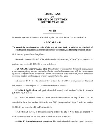
Application Note11SSD TTL-compatible: Another Compact FlashConversely there are other SSD's that are completely compatible with the ATA/ATAPI standard.For example: The specification of a Compact Flash from Toshiba, the “THNCFxxxMBA”:SYMBOL PARAMETERViHInput High VoltageViLMIN0.7 x Vcc2.0VMAXTYP.UNIT TEST CONDITIONSVVcc 3.3VVVcc 5.0VInput Low Voltage0.2 x VccVVcc 3.3V0.8VVVcc 5.0VTable 3: Toshiba, the “THNCFxxxMBA” specifications.If this Compact Flash is connected to the IDE/ATA interface, it will receive 5.0 Volts, therefore it will bereceiving an input voltage that meets its minimum specification from the Compact Flash and therefore will beguaranteed to boot the Host (CPU).In fact,- The minimum input level for the device, referring to Table 3: ViH 3.0 Volts, which is better than therequired 2.0 Volts- The host output level, referring to Table 1 is VoH min is equal to 2.4 VoltsThe Compact Flash receives 2.4 Volts, the specifications calls for at least 2.0 Volts to function; the typicalmargin of error for the TTL signal is 0.4 Volts.
12Application NoteChapter 2 The use of HD and SSD with Eurotech CPU'sThe IDE interfaces found on suitable Eurotech CPU's (see Note 1) are compliant with the followingspecifications: ATA/ATAPI 4 and ATA/ATAPI 6, for modes formally UDMA4.They can function correctly only with a Device whose signal levels are completely compatible withATA/ATAPI.Putting it simply they must have TTL levels of 5.0 Volts.When selecting these devices an evaluation of the datasheet should be made taking careful note of thespecifications, a list of components verified by Eurotech is available upon request, if you have a requirementto use devices other than the listed ones you must check the relative datasheet and specifications.To perform functional tests without first examining the datasheet could cause a false sense of security,problems can be revealed that are in fact caused by secondary factors such as noise, intensity of the test,Input problems etc.It is also worth noting that with the introduction of 3.3Volt Hard Disks with or without a CMOS interface, anevaluation of the datasheet is now advisable even for this kind of Device, up until now they have all beenequally compatible.
Application Note13Chapter 3 A solution for CMOS SSDIn the section dedicated to Compact Flash with CMOS, we underlined the case in which the SSD is suppliedwith 5.0 Volts. This choice becomes spontaneous, in how much input is brought to the Device through theconnector is 5.0 Volts, and the pull-ups are to 5.0 Volts, therefore applying 3.3 Volts to the SSD you will runinto some problems.Supplying the SSD with 3.3 Volts; if possible, it has the advantage in resolving the problem of compatibility.In fact, Supplying with 3.3 Volts- The minimum input level for the device, shown in Table 2: ViH min is equal to 2.0 Volts.- The output from the Host, Shown in Table 1: VoH min is 2.4 Volts.Therefore the SSD receives 2.4V and requires a minimum of 2.4 Volts to see the Voltage high signal, in thiscase a margin of error of 0.0V is acceptable considering that the VoH is smaller than the real voltage for theCPU realized with CMOS fed to 3.3 Volts.Recent Eurotech CPU's and those listed in Note 2, Send the IDE signals with CMOS driver fed with 3.3Volts, therefore the level of VoH declared min for compatibility is equal to 2.4 Volts but it has some variationup to 2.8 Volts.The problems exists that to send the SSD of the largest output signals of the same SSD.Such signals are those with pull-up to 5.0 Volts, which can commonly induce in the SSD a suitable tide inputclamp current through the protection diodes toward the 3.3 Volt input.Such tide is worth around the difference among the feedings I lead the threshold of the diode of protectiondivided for the value in ohms of the parallel of the pull-ups to 5 Volts second standards, or:(5V - 3.3V - 0.9V) / 4.7 kOhms // 10 kOhmsEqual to 0.8 / 3200Or0.2mA /- 10%The datasheets of the SSD's have poor information regarding the input clamp current. Recalling the Philipsdatasheet for the logic family HCT, such value is suitable in around 20mA total for chip.
14Application NoteBeing very distant from such threshold is probable that the SSD's CMOS can be fed with 3.3 Volts andconnected to the IDE interface of the CPU's mentioned without any problem.We leave the responsibility of determining the acceptable value of the input clamp current to the integrator ofthe system, as well as to appraise the general functionality of the solutions he visualizes.
Application NoteChapter 4 NotesNote 1:The following CPU’s are compatible with ATA/ATAPI 4 and ATA/ATAPI 6, for modes formally UDMA4:CPU-1232, CPU-1231, CPU-1230, CPU-1220, CPU-1211, CPU-1210,CPU-1432, CPU-1420, CPU-1410, CPU-7630, CPU-7610 and CPU-7310Note 2:The following CPU’s use an IDE interface with 3.3V CMOS outputs:CPU-1232, CPU-1231, CPU-1230, CPU-1220, CPU-1432, CPU-1420,CPU-1410, CPU-7630, CPU-7610 and CPU-7310Whereas the CPU-1211 and CPU-1210 use a 5 Volt buffer15
16Related DocumentsFor more information refer to the specific CPU user manual and application notes.Where to find usEurotech S.p.A.Via Jacopo Linussio, 1 - 33020 Amaro (UD) ITALYTel. 39 0433 486258 - Fax 39 0433 ://ftp.eurotech.itApplication Note
Application Note17Technical & Sales AssistanceIf you have a technical question, please contact the Eurotech Customer Support Servicetechsupp@eurotech.itOld and new versions of manuals, application notes, patches, drivers and BIOS can be found at:ftp://ftp.eurotech.it/If you have a sales question, please contact your local Eurotech Sales Representative or the Regional SalesOffice for your area.Additional and latest information is available at Eurotech website, located at:http://www.eurotech.it
For example: The specification of a Compact Flash from Toshiba, the "THNCFxxxMBA": SYMBOL PARAMETER MIN MAX TYP. UNITTEST CONDITIONS ViH Input High Voltage 0.7 x Vcc V Vcc 3.3V 2.0V V Vcc 5.0V ViL Input Low Voltage 0.2 x Vcc V Vcc 3.3V 0.8V V Vcc 5.0V Table 3: Toshiba, the "THNCFxxxMBA" specifications.