Transcription
CHAPTER1Introduction to Sun Fire SystemsMost companies want the best solution for their needs, especially when they arepurchasing a computer system. However, designing a reliable system that performswell takes careful consideration and planning.Consider a widely-used analogy—automobiles. A vast range of different types ofvehicles, including sedans, sports cars, convertibles, sport-utility vehicles, trucks,and hybrids is available. Each of these types of vehicles has advantages anddisadvantages. When trying to decide what type of vehicle to purchase, you mustconsider your needs. How many people must it be able to carry? How much powerdoes it need? How much cargo must it hold? Is size a concern? And so forth.You would probably be making a mistake if you purchased a two-seater sports carwhen you had a family of five that regularly attended soccer games. You wouldprobably be making a similar mistake if you bought a sedan with the intent of usingit to haul your trailer and dirt bikes out to the desert on the weekends. For apurchase to be worthwhile, you must ensure that it properly fits your specificrequirements.This analogy may seem trite, but many people do not put nearly as much thoughtinto purchasing a high-end server as they do a car. Instead, a system often ispurchased based on its processor speed or size alone. Little, if any, consideration isgiven to concerns such as how to layout the I/O, how much memory to get, andhow much expansion capacity is really needed.As with the car analogy, you must ensure that the design of your serverconfiguration meets your company’s needs. This design process requires time andeffort, but it pays off in better system reliability, availability, serviceability (RAS) andperformance.This chapter summarizes the RAS and performance features of the Sun Fire systemhardware. The definitions of the RAS features are: Reliability—The ability of the system to run without interruption, to continue tooperate when correctable errors are detected, and to prevent data corruption. Availability—The percentage of time the customer’s system is able to doproductive work. The ability to always recover after a failure by testing andbypassing failed components.1
Serviceability—The system ensures that repair time (downtime) is minimized.This chapter covers these topics in two sections—RAS and Performance.RASThe RAS goals for the Sun Fire system are to protect the integrity of the customer’sdata and to maximize availability. The focus is on three areas: Problem detection and isolation—knowing what went wrong and ensuring thatthe problem is not propagatedTolerance and recovery—absorbing abnormal system behavior and fixing ordynamically circumventing itRedundancy—replicating critical componentsTo ensure data integrity at the hardware level, all data is error correction code (ECC)protected, and address and control buses are protected by parity checks. Thesechecks ensure the containment of errors.For tolerance of errors, resilience capabilities are designed into the Sun Fire systemto ensure that the system continues to operate, even in a degraded mode. The SunFire system can function with one or more processors disabled. In recovering from aproblem, the system is checked quickly to determine the fault and to ensureminimum downtime. To reduce downtime, redundant hardware can be configuredinto the system.ReliabilitySun Fire systems have five categories of reliability capabilities: Reducing the probability of errorsDetecting and correcting errors using error correction code (ECC)Detecting uncorrectable errors with ECC and parity checkingRedundant power and coolingEnvironmental sensingAvailabilityAvailability is the ability of a system to be continually accessible and useful to thecustomer. Sun Fire systems have many features that contribute to this quality,including the ability to:2Introduction to Sun Fire Systems
Test, identify, and de-configure failed components following a system interrupt Configure and boot a usable configuration with a subset of the originalconfiguration Change the configuration without interrupts using dynamic reconfiguration (DR).For higher levels of availability Sun Fire systems can be clustered.ServiceabilityTo reduce repair time, the Sun Fire systems are designed with a number ofmaintenance capabilities and aids. These are used by the Sun Fire systemadministrator and by the service provider.Failing components are listed in the failure logs in such a way that the fieldreplaceable unit (FRU) is clearly identified. You can remove and replace most systemcomponents in a properly configured system during system operation withoutscheduled downtime. If properly configured, CPU/Memory boards, I/O boards, I/Ocontrollers, fans and power supplies can all be replaced while the system is running.Sun Fire RAS FeaturesCPU and System InterconnectThe most important reliability feature in any system is the protection of dataintegrity.The UltraSPARC III processor has parity protection for all major internal cachesand ECC protection for transactions to and from the external caches.The data interconnect has ECC and parity protection throughout the system. Theaddress interconnect has parity protection.CPU Error ProtectionThe CPU corrects errors detected in the internal data and instruction cache SRAMs.When an internal error is detected, the CPU invalidates the cache and retries thedata or instruction load.Sun Fire RAS Features3
Two SRAM modules per CPU reside on the CPU/Memory system board. Thesemodules contain the external cache (Ecache). The CPU corrects all parity errorsdetected during data cache or instruction cache by invalidating and flushing thecache line. The hardware corrects all single bit errors detected by ECC during datatransfers on the fly. ECC also detects and reports any uncorrectable (multibit) errorsto the Solaris OE.System Interconnect Error ProtectionThe system has three types of error protection—data interconnect, addressinterconnect, and error isolation.Data InterconnectThe system protects all data interconnect pathways by using ECC and parityprotection. It generates ECC and parity bits for all data blocks sourced by processorsand PCI I/O controllers (system devices). All data switches in the path for eachtransfer check ECC and parity. The receiving system device checks and corrects ECC.Address InterconnectThe system has parity protection for all address interconnect pathways and checksparity between all system devices and address repeaters. On the Sun Fire 15K/12Ksystems there is also ECC protection on the address and address response crossbarsfor transactions across the centerplane.Error IsolationBecause each of the data switches in the path for every data transfer checks ECC, thesource of ECC errors can be identified in most cases. However, some types of ECCerrors are difficult to isolate. For ECC errors, such as a CPU writing bad ECC intomemory, finding the source is difficult because multiple system devices may readand report the bad ECC. In such cases, the ECC error usually can be isolated to adual CPU data switch or its pair of processors. This is an improvement over theprevious architecture in which it was more difficult to isolate these types of ECCerrors.4Introduction to Sun Fire Systems
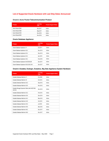
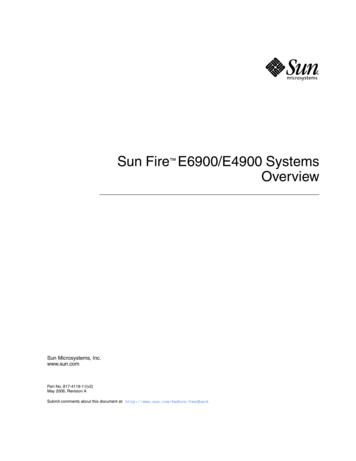
CPU/Memory boardMemoryUltraSPARC IIIAREcacheDCDSEcacheUltraSPARC IIIMemoryMemoryUltraSPARC IIIEcacheDCDSEcacheUltraSPARC IIIDXMemoryLegendAR:Address repeaterDCDS: Dual CPU data switchDX:Data switchSDC: Sun Fire data controllerFIGURE 1-1DataAddressData routingConsole busControl signalsCPU Board Block DiagramSun Fire RAS Features5
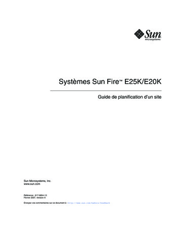
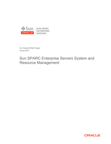
PPAddressPrepeaterAddressrepeaterPPCPU andEcachePEPPPMemoryCPU andEcachePEMemoryPCenterplaneRepeaterboardPDual CPU data switchPECPU andEcachePCPU/memoryboardMemoryPPDual CPU data switchPPCPPDataswitchPPCECPU andEcacheMemoryDataswitchPPPAddressP repeaterPPCIcontrollerEPCI slotsPI/O ModulePCPDataswitchPPCP Parity generate and checkFIGURE 1-26EPCIcontrollerE ECC generate,check and correctPCI slotsC ECC checkSun Fire 6800/4810/4800/3800 Systems Interconnection DiagramIntroduction to Sun Fire Systems
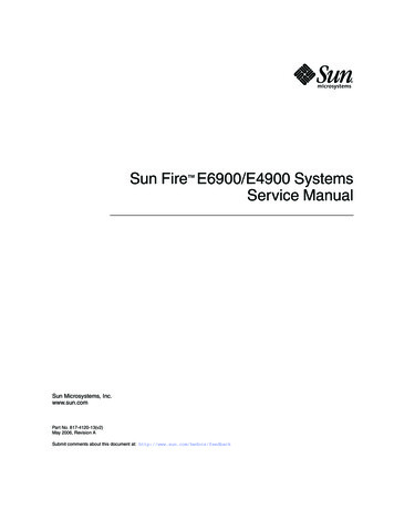
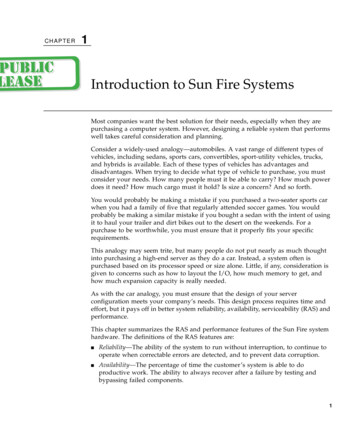
P18 x 18addresscrossbarPEPAddressP CPU andEcachePEMemoryPPCenterplaneDual CPUdata switchMemoryPCPU/MemoryboardMemoryECPU andEcachePP18 x 18responsecrossbarCPU andEcachePEPDual CPUdata switchPCPPdataswitchPPCP18 x 18datacrossbarECPU andEcacheMemoryPSystemdatainterfacePAddressP repeaterPCI slotPPCIcontrollerEPCI slotPI/O modulePCPdataswitchPCP Parity generate and checkFIGURE 1-3PCI slotPPCIE controllerE ECC generate,check and correctPCI slotC ECC checkSun Fire 15K/12K Systems Interconnection DiagramSun Fire RAS Features7
System ControllerA small system called the system controller (SC) manages the Sun Fire systems. TheSC is responsible for all of the functions required to test, configure, and bootdomains. It supplies all system clocks and virtual TOD clocks for the domains andmonitors power and environmental status. It also provides domain control withvirtual key switches and console connections for each domain.Testing and ConfigurationUpon power on or a reset, the SC runs a self test called SCPOST. It then starts theplatform management software.The SC configures and coordinates the initialization, testing, and boot processes.After a system failure, and when the virtual key switch of a domain is turned on, theSC powers on the system components associated with the domain and runs SPOSTfor the domain. SPOST controls the running of LPOST and IPOST. LPOST tests theCPU/Memory boards, I/O boards, and the system interconnect. IPOST tests the PCIcontrollers. The SC then configures the domain based on the components that passthe tests and starts the boot sequence.Environmental MonitoringThe SC monitors the following conditions: Voltage, current, and temperatures for power supplies Voltage and temperatures for all system boards and processors Temperatures of ASICS Fan status and speedIf safe thresholds are exceeded, the SC shuts down components to prevent damageto the system.System Administration and MaintenanceThe SC provides access for platform and domain administration. Access to the SC isby the included RS-232 serial connection or by network connection.Tasks performed at the platform level are:8 SC setup and configuration Allocation of system resources for domains Domain creationIntroduction to Sun Fire Systems
Status display of all domains Power control for all system components Logical enable and disable of components Individual CPU/Memory board tests Component and environmental status display Platform error message administration Platform password setup (Sun Fire 6800/4810/4800/3800 systems) Platform and Domain Security configuration (Sun Fire 15K/12K systems)Tasks performed at the domain level are: Power and boot control Domain status display Logical domain component enable and disable Individual CPU/Memory board tests Domain error message administration Domain password setup (Sun Fire 6800/4810/4800/3800 systems)Redundant System ComponentsAll systems in the Sun Fire system product line can be configured with redundantcomponents. The ability to run with a subset of configured components increasesavailability of the system. As long as one processor with memory and one I/Omodule are functional, the system can run. If the system is configured withredundant connections to storage and network, the access can be maintained usingthese alternate paths.Redundant components include: CPU/Memory boards I/O modules PCI cards System Controller boards Repeater boards (Sun Fire 6800/4810/4800/3800 systems) Sun Fireplane interconnect (Sun Fire 15K/12K systems) Fan trays Power suppliesSun Fire RAS Features9
CPU/Memory BoardsDepending on the model, Sun Fire systems can support up to 18 CPU/Memoryboards. Each board contains two or four CPUs and is capable of runningindependently or together with other boards in a larger domain.I/O ModulesDepending on the model, Sun Fire systems can support up to 18 I/O modules: Sun Fire 15K system supports up to 18 I/O modules, with four PCI slots each. Sun Fire 12K system can have up to nine I/O modules with four PCI slots each. Sun Fire 6800 system can be configured with a combination of four I/O moduleswith eight PCI or four Compact PCI slots each. Sun Fire 4810/4800 can be configured with two I/O Modules with eight PCI orfour Compact PCI slots each. Sun Fire 3800 system is configured with two I/O modules with six Compact PCIslots each.TABLE 1-1 summarizes these configurations.TABLE 1-1I/O Module ConfigurationsSystemI/O ModulesPCI SlotsCompact PCI SlotsSun Fire 15K184 each0Sun Fire 12K94 each0Sun Fire 680048 eachor4 eachSun Fire 4810/480028 eachor4 eachSun Fire 3800206 eachPCI CardsRedundant PCI cards can be configured to provide alternate paths to all peripheralconnections.System Controller BoardsWith two SC boards configured in the system, a failure of the primary SC does notcause a domain interrupt. The system clocks, virtual TOD clocks, and all other SCfunctions fail over to the secondary SC without causing a domain failure.10Introduction to Sun Fire Systems
Repeater BoardsThe Sun Fire 6800/4810/4800 systems contain pairs of Repeater boards. TheRepeater boards contain data and address repeater switches. The Sun Fire 6800contains two pairs of Repeater boards. If one board fails, the system can run indegraded mode on the other pair of boards. The Sun Fire 4810/4800 system isconfigured with one pair of Repeater boards. If one board fails, the system can run indegraded mode on the other board. The Repeater boards can be replaced while thesystem is running. Although the Sun Fire 3800 system has the same ability to run indegraded mode in the case of a failure, the functionality of the Repeater boards isbuilt into the centerplane and cannot be replaced without an interrupt of the system.TABLE 1-2 summarizes these configurations.TABLE 1-2Repeater Board ConfigurationsSystemRepeater boardsSun Fire 3800Functionality is built into the centerplaneSun Fire 4810/48001 pairSun Fire 68002 pairsSun implements the Sun Fire 15K/12K interconnect differently than the midrangesystems. The interconnect consists of three independent 18 way crossbars—one fordata, one for addresses, and one for address responses. Some of the interconnect ismade of multiple ASICs that reside on the centerplane that cannot be replaced whilethe system is running. If one of the crossbars fails, the system can run in degradedmode while the other crossbars continue with full bandwidth. Depending on thefailure, the degraded crossbar may be configured to affect a single domain.Fan TraysAll Sun Fire systems can be configured with redundant fan trays. All fan trays canbe replaced while the system is running.Power Input and SuppliesThe Sun Fire 6800/4810/4800/3800 systems can be configured with up to fourseparate AC input connections. The systems and peripherals can be connected totwo different AC input power grids using two Redundant Transfer Units (RTU),each with two redundant transfer switches (RTS).Sun Fire RAS Features11
The Sun Fire 15K/12K systems are configured with six dual AC-DC power supplies,each with two AC input connections. The power supplies convert the AC voltage to48 VDC. The 48 VDC is supplied to all of the system modules. Each system modulecontains its own on-board DC-DC converter to supply the lower DC voltages neededby the logic components local to each module. A failure of a DC-DC converter onlyaffects that board.Domains and PartitionsThe definitions of these features are:Domain—The ability to create logically independent multiple sections within apartition, with each domain running its own operating system. The Sun Fire 6800system can have up to four domains. The Sun Fire 4810/4800/3800 systems can eachhave up to two domains. Each instance of the Solaris Operating Environment(Solaris OE) runs in its own domain. Domains do not depend on each other and donot interact with each other. Partition—A partition differs from a domain in the level of isolation. The Repeaterboards are logically isolated from each other so the system functions as twoseparate servers. On a Sun Fire 6800 system, segments can be configured to residecompletely within a single internal Sun Fire 6800 power grid. The Sun Fire 15K/12K systems interconnect does not use Repeater boards and does not supportmultiple partitions.A Sun Fire system can be logically divided into multiple domains. Since eachdomain is comprised of one or more system boards, a domain can have anywherefrom two to 106 processors (on the Sun Fire 15K system). Each Sun Fire system hasat least one domain to support the main functionality of the system.Additional domains can be used for: Testing new applicationsOperating system updatesConfiguring several domains to support separate departmentsEach domain runs its own instance of the operating system and has its ownperipherals and network connections. Domains can be configured withoutinterrupting the operation of other domains on the same system.While production work continues on the remaining (and usually larger) domain,there is not any adverse interaction between any of the domains. You can gainconfidence in the stability of applications or upgrades without disturbing productionwork. When the testing work is complete, the system can be rejoined logicallywithout rebooting (there are no physical changes when you use domains). Thus, ifproblems occur, the rest of your system is not affected.12Introduction to Sun Fire Systems
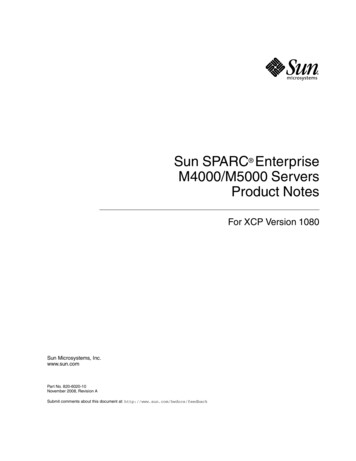
The Sun Fire 15K/12K systems can be configured with up to 18/9 domains. The SunFire 15K/12K systems do not use partitions. The Expander boards are responsiblefor domain separation.Single segmentSun Fire 6800Power grid 0FS0(RP0)FS1(RP1)Dual segmentSun Fire 6800Power grid 1FS2(RP2)FS3(RP3)Power grid 0FS0(RP0)FS1(RP1)Power grid 1FS2(RP2)FS3(RP3)Partition 0Partition 0Partition 1Domain ADomain ADomain CDomain BDomain BDomain DSingle segmentSun Fire 4810/4800/3800Dual segmentSun Fire 4810/4800/3800Power grid 0Power grid 0FS0(RP0)FS2(RP2)FS0(RP0)FS2(RP2)Partition 0Partition 0Partition 1Domain ADomain ADomain CDomain BFIGURE 1-4Sun Fire 6800/4810/4800/3800 Domain and Partition AllocationsMechanical ServiceabilityConnectors are keyed so that boards cannot be installed upside down. Special toolsare not required to access the inside of the system. This is because all voltages withinthe cabinet are considered extra-low voltages (ELVs) as defined by applicable safetyagencies.Sun Fire RAS Features13
No jumpers are required for configuration of the Sun Fire system. This makes itmuch easier to install new and/or upgraded system components. There are no slotdependencies other than the special slots required for the SC and Repeater boards.The Sun Fire system cooling-system design consists of redundant, hot-swappablemodules. Standard proven parts and components are used wherever possible. Sundesigns the field-replaceable units (FRUs) and subassemblies for quick and easyreplacement with minimal use of tools required.PerformanceThis section describes the performance features of the Sun Fire system hardware.UltraSPARC III ProcessorThe UltraSPARC III is a high-performance implementation of the 64-bit SPARC V9architecture.Features of the UltraSPARC III CPU include:14 Full binary compatibility with all UltraSPARC CPU applications VIS instruction set for better 2D and 3D graphic processing 4-way superscalar 14-stage, non-stalling pipeline Integrated memory controller L1 caches: integrated instruction (32 kilobytes) and data (64 kilobytes) L2 cache: 8 megabytes MP scalability: Over 1000 CPUs per system System bus: Sun Fireplane interconnect at 150 MHz Error checking and correction (ECC) in external cacheIntroduction to Sun Fire Systems
TABLE 1-3 lists the UltraSPARC III CPU performance improvements over theUltraSPARC II CPU performance.TABLE 1-3UltraSPARC III CPU Performance ImprovementsItemImprovementClock frequencyApproximately 2XData cache size4XInstruction cache size2XMemory bandwidth2 to 3XExternal cache bandwidth2XCPU/Memory BoardThe CPU/Memory board is common to all Sun Fire mid-range and high-endsystems. The CPU/Memory board holds up to four processors. Each processor hasan associated memory subsystem of eight DIMMs, so memory bandwidth andcapacity both scale as processors are added. The memory capacity of the board is 32gigabytes using 1-gigabyte DIMMs. The maximum memory bandwidth on a board is9.6 gigabytes per second. The CPU/Memory board has a 4.8 gigabyte per secondconnection to the rest of the system.I/O ModulesEach Sun Fire system I/O module contains two PCI controllers. Each controllerprovides one 66 MHz PCI bus, and one 33 MHz PCI bus. Each PCI bus contains twoor more slots for PCI cards. A Sun Fire I/O Module has a 2.4 gigabyte per secondconnection to the rest of the system.System InterconnectAll Sun Fire systems use the Sun Fireplane interconnect architecture, which is thecoherent shared-memory protocol used by the UltraSPARC III/IV processorgeneration. Sun Microsystems uses an improved system interconnect with each newprocessor generation to keep system performance scaling with CPU performance.Performance15
The Sun Fireplane architecture is an improvement over the previous generationUltra Port Architecture (UPA). The system clock rate is increased by fifty percentfrom 100 megahertz to 150 megahertz. The snoops-per-clock is doubled from onehalf to one. Taken together, these improvements triple the snooping bandwidth to150 million addresses per second. The maximum data bandwidth for the Sun Fire6800 and smaller systems is 9.6 gigabytes per second—triple that of the previousgeneration Sun Enterprise 6500/5500/4500/3500 systems.The Sun Fireplane architecture also adds a new layer of point-to-point directorycoherency protocol, for use in systems that require more bandwidth than a singlesnooping bus can provide coherency for. This facility allows coherency to bemaintained between multiple snooping buses, and is used in the Sun Fire 15K/12Ksystems. TABLE 1-4 lists the Sun Fire system interconnect specifications.TABLE 1-4Sun Fire System Interconnect SpecificationsSun Fire 3800systemSun Fire4810 / 4800systemsSun Fire 6800systemSun Fire 15K/12K systemsSystem clock150 MHzCoherency protocolSnoopingSnooping on each board set,directory across centerplaneAddress interconnect1 snooping bus18 snooping buses,18x18 global addresscrossbar,18x18 global responsecrossbarCPU/Memory boardinternal bisectionbandwidth4.8 Gbytes/secCPU/Memory boardexternal bandwidth4.8 Gbytes/secI/O boardexternal bandwidth2.4 Gbytes/secInter-board datainterconnect4 x4 crossbarSame-board bandwidth9.6 Gbytes/secDifferent-board bandwidth4.8 Gbytes/sec16Introduction to Sun Fire Systems5 x 5 crossbar10 x10 crossbar18 3x3 crossbars,18x18 global crossbar121 Gbytes/sec9.6 Gbytes/sec43/21.6 Gbytes/sec
Centerplane ImplementationThe centerplane implementation depends upon system size. The Sun Fire 6800 and4810/4800 systems have passive centerplanes, with switch ASICs located on theRepeater boards. The Sun Fire 6800 system uses four Repeater boards to implementa 10x10 data crossbar that connects the CPU/Memory boards and the I/O modulestogether. The Sun Fire 4810/4800 systems use two Repeater boards to implement a5x5 data crossbar. The Sun Fire 3800 system uses an active centerplane. The Repeaterboard functionality is included on the centerplane to implement a 4x4 data crossbar.The Sun Fire 15K/12K systems use an Expander board to implement a 3x3 switchbetween a CPU/Memory board, an I/O module, and the centerplane port.The Sun Fire 15K/12K system has three 18x18 crossbars on the active centerplane toprovide connections between the Expander boards. The three crossbars are separatebusses for address, response, and data transfers. This method keeps address trafficfrom interfering with data traffic. The peak Sun Fire 15K system centerplanebandwidth is 43 gigabits per second and 21.6 gigabits per second for the Sun Fire12K system.System ConfigurationsTABLE 1-5 lists the Sun Fire system maximum configurations.TABLE 1-5Sun Fire System Maximum ConfigurationsSun Fire 3800systemSun Fire 4800systemSun Fire 4810systemSun Fire 6800systemSun Fire 12KsystemSun Fire 2172/1061Number of DIMMs649619228857664 Gbytes96 Gbytes192 Gbytes288 Gbytes576 GbytesMemory capacity(with 1 GbyteDIMMs)CenterplaneRepeater boardsActive0Expander UModules224918Performance17
Sun Fire System Maximum Configurations (Continued)TABLE 1-5Sun Fire 3800systemSun Fire 4800systemSun Fire 4810systemSun Fire 6800systemSun Fire 12KsystemSun Fire 15Ksystemhot-swapCompactPCIPCI and hot-swap CompactPCIhot-swap PCIPCI slots per assembly68 per PCI, 4 per cPCI4Max total PCI slot121632Bulk power supplies236PCI card typesPower requirements100–120VAC or200–240VAC726200–240 VACSystem Controllerboards2Redundant coolingYesRedundant ACinputYesEnclosure36RackmountDeskside orRackmountRackmountSun Fire6800cabinetSun Fire12KcabinetSun Fire15Kcabinet1. Maximum CPU count is attained by putting MaxCPU boards in the I/O slots.System Board Designations and LocationsTABLE 1-6 through TABLE 1-15 list the system board designations and locations.TABLE 1-618System Board AbbreviationsAbbreviationSystem BoardSun Fire SystemIB[6-9]I/O Module6800/4810/4800/3800FPFiller PanelAllIO[0-17]I/O Board15K/12KMaxCPU[0-17]Dual Processor Board15K/12KSB[0-17]CPU/Memory BoardAllSC[0-1]System ControllerAllSCPER[0-1]System Controller Peripheral Board15K/12KIntroduction to Sun Fire Systems
TABLE 1-7Sun Fire 6800 System Board LocationsFrontSC0SB0SB2SB4SB1SB3SB5SC1TABLE 1-8Sun Fire 6800 System Board LocationsRearIB9IB8RP2RP3RP0RP1IB7TABLE 1-9IB6Sun Fire 4810 System Board ce19
Sun Fire 4800 System Board LocationsTABLE 1-10RearIB8SC1RP0IB6RP1SB0SB2SB4SC0Sun Fire 3800 System Board LocationsTABLE 1-11FrontSC1SB2SC0SB0IB6TABLE 1-12IB8Sun Fire 15K System Board CPUIO2/MaxCPUIO1/MaxCPUIO0/MaxCPUIntroduction to Sun Fire SystemsSC0SCPER0
TABLE 1-13Sun Fire 15K System Board E 1-14SC1SCPER1Sun Fire 12K System Board e21
TABLE 1-15Sun Fire 12K System Board FPSCPER1System Dimensions and FootprintsFIGURE 1-5 shows the dimensions and footprints of the Sun Fire 4810/4800/3800systems. FIGURE 1-6 shows the dimensions and footprints of the Sun Fire 15K/6800systems.22Introduction to Sun Fire Systems
24"Sun Fire 3800Sun Fire 4800Sun Fire 4810Rackmount8 processors2 CPU/Memory boards2 I/O assemblies2 domainsDeskside or rackmount12 processors3 CPU/Memory boards2 I/O assemblies2 domainsRackmount12 processors3 CPU/Memory boards2 I/O assemblies4 domainsFIGURE 1-5Sun Fire 4810/4800/3800 Systems Footprints and Dimensions24"33"SunSunCPU/Memoryboards (9 morein back)CPU/Memoryboards (fourI/O modulesin back)I/O modules/MaxCPU modules(9 more in back)75"PowersuppliesPower supplies(3 more in back)RTS/RTU(1 morein back)FIGURE 1-656"65"Sun Fire 6800Sun Fire 15KCabinet24 processors6 CPU/Memory boards4 I/O assemblies4 domainsCabinet72-106 processors18 CPU/Memory boards18 I/O assemblies18 domainsSun Fire 15K/6800 Systems Footprints and DimensionsPerformance23
6 Introduction to Sun Fire Systems. FIGURE 1-2. Sun Fire 6800/4810/4800/3800 Systems Interconnection Diagram. Address repeater Address repeater Address repeater Data switch Data switch Data switch Repeater board C e n terp l a n e I/O Module CPU/memory board CPU and Ecache Memory CPU and Ecache Memory Dual CPU data switch CPU and Ecache Memory .