Transcription
PCI-104 SpecificationVersion 1.0November 2003Please NoteThis specification is subject to change without notice. While every effort has been made toensure the accuracy of the material contained within this document, the PC/104 EmbeddedConsortium shall under no circumstances be liable for incidental or consequential damages orrelated expenses resulting from the use of this specification. If errors are found, please notifythe PC/104 Embedded Consortium.PC/104, PC/104-Plus, and PCI-104 are trademarks of the PC/104 Embedded Consortium. Allother marks are the property of their respective companies.Copyright 2003, PC/104 Embedded Consortium
REVISION HISTORY1.0, Nov, 2003a. Formatted to meet the requirements of the PC/104 Embedded Consortium.PCI-104 Specification Version 1.0 — Page i
TABLE OF CONTENTS1.INTRODUCTION . 11.11.21.31.4SUMMARY OF KEY DIFFERENCES FROM PC/104 SPECIFICATION: . 1SUMMARY OF KEY DIFFERENCES FROM PC/104-PLUS SPECIFICATION:. 1SUMMARY OF KEY DIFFERENCES (120-PIN PCI AND PCI LOCAL BUS SPECIFICATION) . 1REFERENCES . 22.A POSSIBLE MODULE STACK CONFIGURATION . 33.PCI SIGNAL DEFINITION. 43.1PCI BUS SIGNAL DESCRIPTION . 53.1.1Address and Data. 53.1.2Interface Control Pins . 53.1.3Error Reporting. 53.1.4Arbitration (Bus Masters Only). 53.1.5System. 63.1.6Interrupts. 63.2SIGNAL GROUPING. 74.ELECTRICAL SPECIFICATION. 104.1PCI BUS . 104.1.1Signal Definitions . 104.1.2Signal Assignments. 104.1.3Power and Ground Pins . 104.1.4AC/DC Signal Specifications . 104.2MODULE POWER REQUIREMENTS . 114.3PCI SIGNALING VOLTAGE (VI/O) REQUIREMENTS . 114.3.1PCI Host Module . 114.3.2Add-In Modules . 125.LEVELS OF CONFORMANCE . 135.15.26.PCI-104 "COMPLIANT" . 13PCI-104 "BUS-COMPATIBLE". 13MECHANICAL SPECIFICATION . 146.16.26.36.4CLOCK TRACE LENGTHS. 14MODULE DIMENSIONS . 14CONNECTOR AND SHROUD . 14BOARD IDENTIFIER . 14APPENDICESA. MECHANICAL DIMENSIONS. A-1B. BUS SIGNAL ASSIGNMENTS. B-1PCI-104 Specification Version 1.0 — Page ii
TABLE OF FIGURESFIGURE 1: A POSSIBLE MODULE STACK CONFIGURATION .3FIGURE 2: PCI PIN LIST .4FIGURE 3: INTERRUPT ROUTING FOR A DESKTOP PC .7FIGURE 4: SIGNAL SELECT ON AN EXPANSION BOARD .8FIGURE 6: PCI-104 MODULE DIMENSIONS . A-2FIGURE 7: PCI CONNECTOR . A-3FIGURE 8: PCI CONNECTOR SHROUD . A-3FIGURE 9: PCI CONNECTOR SPECIFICATIONS . A-4TABLE OF TABLESTABLE 1: ROTARY SWITCH SETTINGS .9TABLE 2: MODULE POWER REQUIREMENTS .11TABLE 3: PCI BUS SIGNAL ASSIGNMENTS .B-2PCI-104 Specification Version 1.0 — Page iii
PCI-104 SPECIFICATIONVersion 1.01. INTRODUCTIONThe ISA architecture bus has long been a popular choice for embedded applications. With thepublication of the PC/104 standard in 1992, this bus architecture was available on a small,rugged form factor which has since become an industry standard. As technological requirementsadvanced, a need began to arise for a higher performance bus throughput. This is especially truewhen it comes to graphics devices as well as other high-speed I/O devices such as networks. ThePC/104 Consortium met this challenge by incorporating a PCI bus on the PC/104 form factor,which became to be known as PC/104-Plus. This architecture provides a link to versatile legacyhardware while meeting the high-speed requirements for present and future hardware.To accommodate the gradual replacement of ISA bus devices with PCI devices, the PCI-104 wasapproved by the PC/104 Consortium. PCI-104 is a PCI-only architecture that accommodates theadvances of PCI devices in a small rugged form factor.This document supplies the mechanical and electrical specifications for the “PCI-104” which hasthe advantage of the high-speed PCI bus.1.1 Summary of Key Differences From PC/104 Specification:The AT and XT connectors for the ISA bus have been removed.The component height on the topside has been reduced from 0.435" to 0.345" and the bottomhas been increased from 0.100" to 0.190" to increase the flexibility of the module.Control logic added to handle the requirements for the high-speed bus.1.2 Summary of Key Differences From PC/104-Plus Specification:The AT and XT connectors for the ISA bus have been removed.1.3 Summary of Key Differences (120-pin PCI and PCI Local Bus Specification)The PCI bus connector is a 4x30 (120-pin) 2mm pitch stack-through connector as opposed tothe 124-pin edge connector on standard 32-bit PCI Local Bus.The 120-pin PCI does not support 64-bit Extensions, JTAG, PRSNT, or CLKRUN signals.PCI-104 Specification Version 1.0 — Page 1
1.4 ReferencesThis document covers the addition of the PCI functions. The following documents should beused as reference for a detailed understanding of the overall system requirements:PCI Local Bus Specification Revision 2.2Contact the PCI Special Interest Group office for the latest revision of the PCI specification:PCI Special Interest Group5440 SW Westgate Dr., #217Portland, OR 97221Phone: 503.291.2569FAX: 503.297.1090Email: administration@pcisig.com Website: http://www.pcisig.comIf errors are found in this document, please send a written copy of the suggested corrections to:PC/104 Embedded ConsortiumP.O. Box 78008San Francisco, CA 94107-8008Tel 415.243.2104 Fax 415.836.9094E-mail info@pc104.org Website http://www.pc104.orgPCI-104 Specification Version 1.0 — Page 2
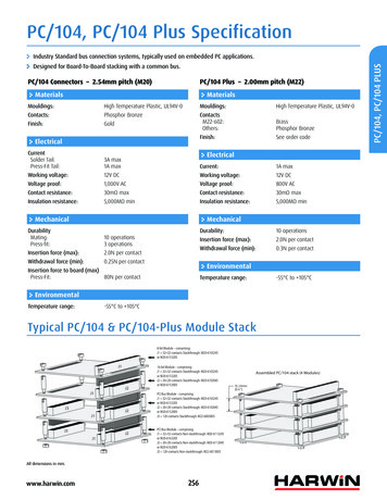
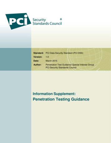
2. A POSSIBLE MODULE STACK CONFIGURATIONFigure 1 shows a typical module stack with two PCI-104 modules, one PC/104-Plus module, onePC/104 16-bit module, and one PC/104 8-bit module. The maximum configuration for the PCIbus of PC/104-Plus modules is four plus the Host Board. If standard PC/104 modules are usedin the stack, they must be the top module(s) because they will normally not include the PCI bus.Figure 1: A Possible Module Stack ConfigurationStackthrough8-bit module0.6 in. (15mm) Spacers (4 plcs.)Stackthrough16-bit module0.6 in. (15mm) Spacers (4 plcs.)StackthroughPC/104-Plus module0.6 in. (15mm) Spacers (4 plcs.)StackthroughPCI-104 module0.6 in. (15mm) Spacers (4 plcs.)Non-stackthroughPCI-104 module0.435 in (11 mm)0.6 in (15 mm)PCI-104 Specification Version 1.0 — Page 3
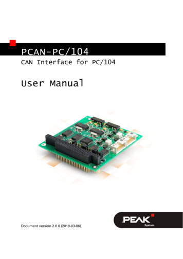
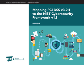
3. PCI SIGNAL DEFINITIONFigure 2 shows the pins in functional groups, with the required pins on the left and the optionalpins on the right side. The shaded pins on the right are unsupported features, but are included toshow the entire PCI bus as defined in the PCI Local Bus Specification Revision 2.2. This versionof the PCI bus is intended as a 32-bit bus running at 33MHz and therefore, 64-bit extension and66MHz1 are not supported at this time. Also not supported are the boundary scan features(JTAG), Present (PRSNT[1:2]#), and Clock running (CLKRUN#). The direction indication onthe pins assumes a combination master/target device.Figure 2: PCI Pin ListRequired PinsOptional PinsLOCK#AD[31:00]Address& #Arbitration(master R64REQ64#ACK64#64-Bit Extension(Not Supported)TDITDOTCKTMSJTAG(Not Supported)TRST#CLKRUN#PRSNT[1:2]#M66EN11Clock Running(Not Supported)Present(Not Supported)66MHz EnableThe PCI bus has been simulated at 33MHz. For the purpose of this specification, 66MHz is not supported. Tosupport future enhancements, the M66EN signal should be grounded on any module that cannot support 66MHz andleft open for modules that can support a 66MHz clock.PCI-104 Specification Version 1.0 — Page 4
3.1 PCI Bus Signal Description3.1.1 Address and DataAD[31:00]C/BE[3:0]#PARAddress and Data are multiplexed on the same PCI pins. A bus transactionconsists of an address phase followed by one or more data phases.Bus Command/Byte Enables are multiplexed. During the address phase ofa transaction, they define the bus command. During the data phase, they areused as byte enables.Parity is even parity across AD[31:00] and C/BE[3:0]#. Parity generation isrequired by all PCI signals.3.1.2 Interface Control PinsFRAME#TRDY#IRDY#STOP#DEVSEL#IDSELLOCK#Cycle Frame is driven by the current master to indicate the beginning of anaccess and will remain active until the final data cycle.Target Ready indicates the selected device’s ability to complete the currentdata phase of the transaction. Both IRDY# and TRDY# must be asserted toterminate a data cycle.Initiator Ready indicates the bus master's ability to complete the current dataphase of the transaction.Stop indicates the current selected device is requesting the master to stop thecurrent transaction.Device Select, when actively driven, indicates the driving device has decodedits address as the target of the current access.Initialization Device Select is used as a chip-select during configuration readand write transactions.Lock indicates an atomic operation to a bridge that may require multipletransactions to complete.3.1.3 Error ReportingPERR#SERR#Parity Error is for reporting data parity errors.System Error is for reporting address parity errors.3.1.4 Arbitration (Bus Masters Only)REQ#GNT#Request indicates to the arbitrator that this device desires use of the bus.Grant indicates to the requesting device that access has been granted.PCI-104 Specification Version 1.0 — Page 5
3.1.5 SystemCLKRST#M66ENClock provides timing for all transactions on the PCI bus and is an input toevery PCI device.Reset is used to bring PCI-specific registers, sequencers, and signals to aconsistent state.66 MHz Enable indicates to a device whether the bus segment is operating at33 MHz or 66 MHz. The PCI bus has been simulated at 33MHz. For thepurpose of this specification, 66MHz is not supported. To support futureenhancements, the M66EN signal should be grounded on any module thatcannot support 66MHz and left open for modules that can support a 66MHzclock.3.1.6 InterruptsINTA#INTB#INTC#INTD#Interrupt A is used to request Interrupts.Interrupt B is used to request Interrupts.Interrupt C is used to request Interrupts.Interrupt D is used to request Interrupts.PCI-104 Specification Version 1.0 — Page 6
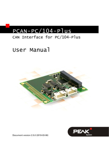
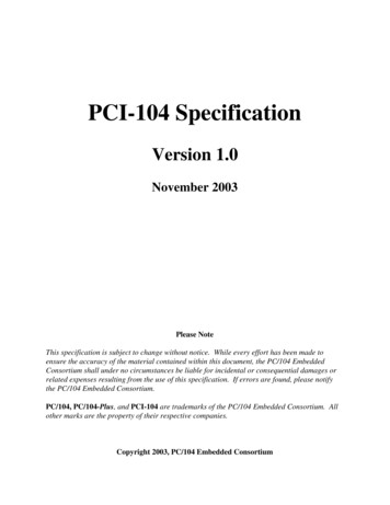
3.2 Signal GroupingThe PCI-104 architecture was developed to take advantage of the versatility and simplicity of thePC market for embedded applications. Like the desktop PC, PCI-104 has the ability to addauxiliary boards to expand the capabilities of the CPU. But instead of using slot cards, PCI-104adds additional modules using stack-through connectors. This has two advantages: it reduces thesystem size and it makes the system more rugged so that it can better withstand shocks andvibrations.To realize a stack-through architecture, a means of selecting the appropriate signals for eachexpansion card must be established that will easily allow for the installation and configuration ofadd-in PC/104-Plus and PCI-104 modules. The signals in question include CLKx, IDSELx,REQx#, GNTx#, and INTx# lines. Normal desktop computers overcome this problem by routingonly the necessary signals to each of the slot connectors. For example, on a desktop PC, onlyCLK1, IDSEL1, REQ1#, and GNT1# are routed to PCI slot 1. Likewise, CLK2, IDSEL2,REQ2#, and GNT2# are routed to slot 2.The interrupts on a desktop PC are handled in a different manner. All four interrupts from theinterrupt controller are routed to each PCI slot connector. By convention INTA# on anexpansion card is used for single-function devices and the remaining interrupts are used in thecase of multi-functional devices. This could place a large burden on INTA# since all of theexpansion cards would use this interrupt. To alleviate the burden, PC manufacturers stagger theinterrupts on the motherboard to each of the PCI connectors. This is shown in Figure 3.Figure 3: Interrupt routing for a desktop board 1PCISlotboard 2INTA#INTB#INTC#INTD#PCI HostPCIConnector 1PCIConnector 2MotherboardPCIConnector 3PCI-104 Specification Version 1.0 — Page 7
Since PCI-104 is a stack-through architecture, there is only one connector to which all of theexpansion boards must connect. A means of selecting the appropriate signals must beestablished that will easily allow for the installation and configuration of add-in PC/104-Plus andPCI-104 modules. Figure 4 shows such a method that can be applied to the expansion boards.Figure 4: Signal Select on an Expansion y Switch1C 123 20476 5 40123DUAL4 TO 10 NT3#0123DUAL4 TO 10 NTA#0123DUAL4 TO 10MUX123A0A1A0A1A0A1EN#EN#EN#vccThis Mux is Only Requiredfor Bus MastersINT0#INT1#1 or 2 Muxes are recommendedfor INTA Routing.See Table 1 for routing ofINT2# and INT3#.The multiplexer chips on the expansion board serve as the equivalent of having multiple PCI slotconnectors on the motherboard of a desktop PC. To select the appropriate REQ#, GNT#, CLK,and INT signals for the expansion module, the rotary switch must be adjusted for the position onthe stack.PCI-104 Specification Version 1.0 — Page 8
For expansion modules requiring more than one interrupt, the staggering of the INTx# lines isaccomplished on the expansion module prior to the multiplexers. Figure 5 shows the interruptrouting on a PCI Host Module and on an expansion module with two functions. The Add-onModule portion of Figure 5 shows how the right-hand multiplexer of Figure 4 fits onto an add-onmodule. If a board has a single function then only half of the multiplexer is required.Figure 5: INT# SelectINTA#INTB#INTC#INTD#INTW#INTX#INTY#INTZ#PCI HostPCIConn.INTA#INTB#INTC#PCIDual INTD#Device4 to 1MUX INTB#INTC#INT1#INTD#INTA#INT0#PCI Host ModuleINTA#INTB#INTC#INTD#PCIConn.Add-on ModuleThe multiplexer chips are Dual 4:1 Mux/Demux chips. They provide a 5Ω switch that connectsthe input and output together. These switches provide a bi-directional path with no signalpropagation delay other than the RC delay of the on resistance of the switch and the loadcapacitance. This is typically 250ps at 50pF load. Use one Mux for 1 to 2 interrupts or twoMuxes for 3 to 4 interrupts.While other methods of configuring the modules are possible and permissible, the rotary switchis clean and provides for the least possible error in configuration.Table 1 shows the appropriate switch setting and signals used for each module in the stack.Table 1: Rotary Switch SettingsSwitch Position0 or 41 or 52 or 63 or 7Module INT1#INTB#INTC#INTD#INTA#PCI-104 Specification Version 1.0 — Page #
4. ELECTRICAL SPECIFICATION4.1 PCI BusThe PCI Bus mechanical interface is a stackable 4x30 header. This interface carries all of therequired PCI signals per PCI Local Bus Specification Revision 2.2.4.1.1 Signal DefinitionsFor full details on the electrical requirements for the PCI bus, reference the PCI Local BusSpecification Revision 2.2.4.1.2 Signal AssignmentsSignals are assigned in the same relative order as in the PCI Local Bus SpecificationRevision 2.2, but transformed to the corresponding header connector pins. Because of thestack-through nature of the bus, slot-specific signals are duplicated for each plug-in module.The system has been designed to accommodate 4 modules, which are PC/104-Plus, PCI104, or a combination of the two, so multiple sets of the signals have been duplicated toaccommodate one signal for each module. These four signal groups include: IDSEL[3:0],CLK[3:0], REQ#[3:
PCI-104 Specification Version 1.0 — Page 3 2. A POSSIBLE MODULE STACK CONFIGURATION Figure 1 shows a typical module stack with two PCI-104 modules, one PC/104-Plus module, one PC/104 16-bit module, and one PC/104 8-bit module. The maximum configuration for the PCI bus of PC/104-Plus mo