Transcription
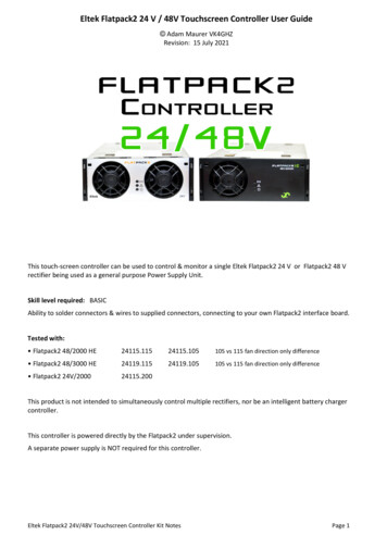
The leader inrugged fiber opticRLH Industries, Inc.technology.USER GUIDEU-144 2017A-0508AC/DC Hi-Density 48V Power SupplyWall Mount, NEBS Level 3 ApprovedP/N 8806-1214-01Key Features Isolated 48VDC power source Power terminals for up to 12 devices Battery backup provides 3 to 10 hours of uninterruptible power Operates off standard 115VAC power Convenient LED indicators providerectifier status Ideal for powering telco equipment Wide operating temperature range Batteries are field replaceable Compact, wall mount form factor Includes all hardware and wiring for installationContentsKey Features 1Description 1DescriptionGeneral Safety Practices 2The AC/DC Hi-Density Power Supply (P/N 8806-1214-01) isan isolated 48 VDC power source. The power supplyconsists of an AC/DC rectifier and a 48 V, 7.0 AH backupbattery pack. The AC/DC rectifier is contained in a modifiedKeptel housing.The Power Supply requires a 115 VAC main supply foroperation. A 3 Amp fuse on the main input and a 6Amp fuseon the DC output protect the power supply. A blue LED onthe housing indicates normal operation of the AC/DC rectifier.A yellow LED indicates DC output on the plus and minuswiring terminals.The 7.2 Amp/hr. battery backup provides uninterruptiblepower for 3-10 hours, depending on the load. The PowerSupply will operate between –40 C and 50 C.Mounting Information 2Installation 3Connecting Equipment 5Troubleshooting 6Specifications 7Compliance InformationThe RLH AC/DC 48V Hi-Density Power Supply System is compliant with the following industry standards: NEBS Level 3 GR-1089 GR-63RLH Industries, Inc. Tel. 866-DO-FIBER Fax 714 532-1885 www.fiberopticlink.comPage 1
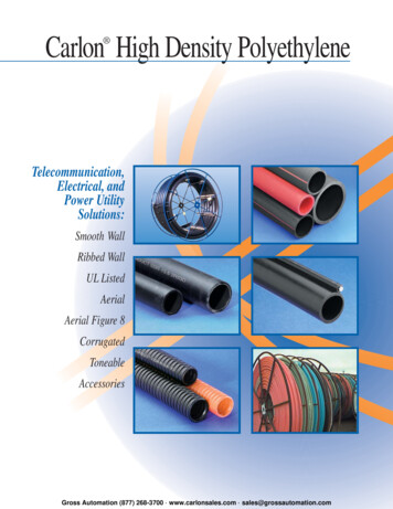
General Safety PracticesThe equipment discussed in this document may require tools designed for the activity being described.RLH recommends that service personnel be familiar with the correct handling and use of any installationequipment used, and follow all safety precautions including the use of protective personal equipment asrequired.Caution - Severe Shock Hazard Never install during a lightning storm or where unsafe high voltages are present. This power supply uses 115VAC line power and high DC voltages may be present on the interior components. Do not touch circuit boards or transformers when power is applied. Use caution when handling copper wiring and follow appropriate safety regulations. An external Surge Protective Device (SPD) is not required.Mounting InformationBoth the power supply and the backup battery are intended to be wall mounted using the supplied hardware. The power supplyhousing is not weatherproof, and must be mounted indoors or in a weather proof enclosure if used outdoors. The power supply unit weighs approximately 11 lbs. (5kg). The backup battery pack weighs approximately 26 lbs. (12kg).Mounting dimensions12.5” (318mm)9.3” (236mm)16.0”(406mm)11.5”(292mm)"Leave room for wireconnections and changing fusesLeave room forwiring exiting power supplyRLH Industries, Inc. Tel. 866-DO-FIBER Fax 714 532-1885 www.fiberopticlink.comPage 2
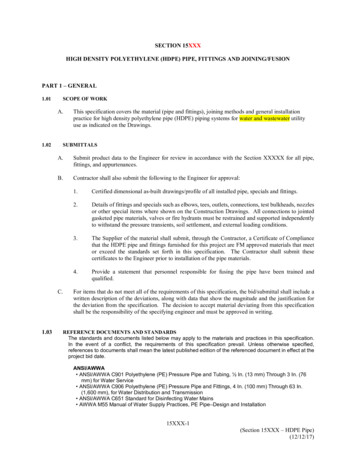
InstallationLocate the power supply unit within 6 feet of an AC power outlet. Do not plug the power supply into ACoutlet yet. Mount the Power Supply to a plywood backplane using the wood screws provided. If mountingto another type of backplane be sure to have the correct hardware.After attaching housing to the backplane, use a screwdriver to open the box. Locate battery backupwithin reach of the 30-inch battery cable and use the four (4) wood screws provided to attach housing tothe backplane.CAUTION Connecting the battery backup to the rectifier unit will apply battery output of 48 VDC across theDC output terminalsBatteryConnectorsLocate closeenough for batterycable to reachBattery terminalson bottomRLH Industries, Inc. Tel. 866-DO-FIBER Fax 714 532-1885 www.fiberopticlink.comPage 3
Battery connectionConnect the battery cable to the battery backup using the spade lugs (red to and black to -).Route battery cablesthrough grommetDC output terminals"Backup battery cablesRoute the battery cable through the grommet at the bottom of the rectifier unit. Note that the rubbergrommet can be removed for this process. Attach the battery cables to the 2 battery connectors andreplace the grommet.Set transformer secondary outputMeasure the AC RMS voltage at the wall socket. Use the connection chart to select the correspondingleads from each transformer."MultimeterAC Power SourceMeasurementLead Color108 VAC to 113 VACGreen Lead113 VAC to 119 VACYellow Lead119 VAC to 125 VACRed LeadRLH Industries, Inc. Tel. 866-DO-FIBER Fax 714 532-1885 www.fiberopticlink.comPage 4
CAUTION Power supply must be removed from AC power source when setting the transformer output Replace protective caps on unused leadsIf necessary, remove the protective caps from the leads as indicated and connect them to the powersupply circuit boards as shown. Replace the protective caps onto the unused leads.Select Red, Green orYellow leadReplace safety capswhen changing leadsConnect selectedlead to output boards"After connecting the transformer leads, close the access door and secure using a nut driver.Connect AC powerConnect rectifier AC power cord to the AC main outlet. Power supply is now in operation. The blue LED indicates normal operation of the AC/DC rectifier The yellow LED indicates DC output on the plus and minus wiring terminalsConnecting equipmentTo connect equipment, carefully make a hole in the rubber grommets membrane with a screwdriver andpass connecting wires through. Connect positive ( ) and negative (–) wires to the screw down terminal.RLH Industries, Inc. Tel. 866-DO-FIBER Fax 714 532-1885 www.fiberopticlink.comPage 5
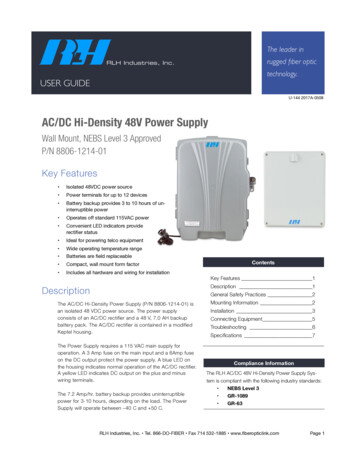
TroubleshootingTroubleshooting the AC/DC Power Supply always begins with the observation of the two (2) LEDS on theface of the housing. Remember, the Blue LED indicates AC INPUT and RECTIFIER output. The yellow LEDindicates DC OUTPUT on ( ) and (-) terminals.Blue LEDYellow LEDDescriptionONONNormal Operation. Note that these LEDS will be ON even if the Battery Backup isdischarged or disconnected from the system.OFFONLoss of AC Input or Rectifier output. Power Supply is operating on Battery Backup.Check main supply. Check AC input fuse 3 Amp (fast blow) (5x20mm) on power supplyPCB. Replace if blown.ONOFFOutput voltage less than 48 VDC. Check load on power supply.Disconnect all cards/equipment from the DC output terminal. If yellow LED comes on, adefective card or unit is indicated. Reconnect cards one at a time to pinpoint trouble.Check that the Yellow LED is not shorted or disconnected.OFFOFFPower Supply inoperative. Batteries discharged or disconnectedCheck battery fuse (F1) 6 Amp (fast blow). Replace if blownCheck main AC supply. If main supply is OK, check fuse on transformers. Replace with 3Amp (fast blow) (5x20mm). If still no output, power supply must be repaired. Replace withspare and return inoperative power supply to RLH Industries, Inc.Transformer fusesAC Input fuses onpower supply PCBSpare fuses infuseholdersPower supply fuse locationsRLH Industries, Inc. Tel. 866-DO-FIBER Fax 714 532-1885 www.fiberopticlink.comPage 6
6 Amp– – 6 AmpView from bottomof battery packFuses on bottomof battery pack"Battery pack fuse locationsIf trouble is encountered, verify all connections. Double check the secondary transformer wiring andensure that it corresponds to the incoming AC voltage. Batteries may require 24 hours to charge fullybefore using. If trouble persists, replace the unit and retest. If technical assistance is required, contact theRLH Industries, inc. technical support department:800-877-1672 (6 am to 6 pm- PST),or call our 24/7 Technical/Customer Service: (714) 366-2503 or (714) 457-5740SpecificationsInput Voltage108VAC 120VAC (Range set on transformer)Output Voltage(Without batteries) 55.2 VDC /– 0.1VDC from 0 to 2.1 Amp loadBattery Backup48V from (4) 12-volt batteries wired in seriesBattery Capacity7.0 Amp/hrBattery TypeRechargeable Gel CellTemperature Limits-40F to 140F (-40C to 60C)Humidity0-100% non-condensingHousing DimensionsPower Supply:H16” x W12.5” x D5.5”(H406mm x W318mm x D140mm)Battery Pack:H11.5” x W9.3” x D6.25”(H292mm x W236mm x D159mm)WeightPower Supply: 11.0 lbs (5kg)Battery Pack: 26 lbs. (12kg)RLH Industries, Inc. Tel. 866-DO-FIBER Fax 714 532-1885 www.fiberopticlink.comPage 7
Technical SupportNormal technical support:(714) 532-1672(Mon - Fri 6am - 6pm PST)Toll Free 800-877-1672Toll Free 866-DO-FIBEREmail:support@fiberopticlink.com24/7 technical support:Toll Free 1-855-RLH-24X7(Outside normal business hours)Toll Free 1-855-754-2497Contact InformationCorporate Headquarters:RLH Industries, Inc.936 N. Main StreetOrange, CA 92867 USAPhone:(714) 532-1672Toll Free 1-800-877-1672"Toll Free 1-866-DO-FIBERFax:(714) 532-1885Email:info@fiberopticlink.comWeb site:www.fiberopticlink.comRLH Industries, Inc.936 N. Main Street, Orange, CA 92867 USAT: (714) 532-1672F: (714) 532-1885Please contact your RLH sales representativefor pricing and delivery information.Specifications subject to change without notice.RLH Industries, Inc. Tel. 866-DO-FIBER Fax 714 532-1885 www.fiberopticlink.comPage 8
Toll Free 800-877-1672 Toll Free 866-DO-FIBER Email: support@fiberopticlink.com 24/7 technical support: (Outside normal business hours) Toll Free 1-855-RLH-24X7 Toll Free 1-855-754-2497 Corporate Headquarters: RLH Industries, Inc. 936 N. Main Street Orange, CA 92867 USA Phone: (714) 532-1672 Toll Free 1-800-877-1672 Toll Free 1-866-DO-FIBER