Transcription
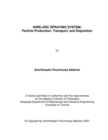
One-Wire Lightning MonitorThis article describes the construction of an experimental lightningmonitor for use with the Dallas Semiconductor 1-wire bus. This monitorprovides real-time data on lightning activity by counting the number oflightning strikes in the area. This device is designed to either be usedstand-alone or to supplement the WS-1 One-Wire Weather Station,providing the weather hobbyist additional weather data.The necessary software to display the data is left up to the reader. Thedata is accessed by reading the value of the counter via the 1-wirebus. Currently versions of TiniWeatherServer, as well as DalSemi’sTMEX are capable of reading the counter value.The hardware is divided into 3 sections: the Lightning Sensor Unit(LSU), the Interface Board, and the Counter Board. The design
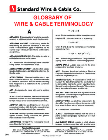
presented built each section separately, however is there no reason allthree circuits can’t be combined on a single board.The counter used in this example is a DalSemi Rain Gauge board,available as part of the 1-wire Rain Gauge. Alternatively, you can buildthe counter board from scratch.The entire lightning detector is now also available in a kit or fullyassembled form at Hobby-Boards.The Lightning Sensor UnitThe lightning sensor unit performs the lightning detection. Referring tothe schematic, energy from the lightning is received from the antenna,passes through the hi-gain Darlington pair, allowing current to flowthrough Q2 during each lightning strike.Schematic for the Lightning Sensor Unit
Layout for the LSU boardThe antenna is simply a 30 cm copper rod or wire. The circuit can beassembled on a small piece of perf board. A possible layout is shownabove. The low side of the LSU (black or - lead) must be connected toa good earth ground in order for the LSU to work properly. A metalwater pipe or a ground rod near the installation should work fine.
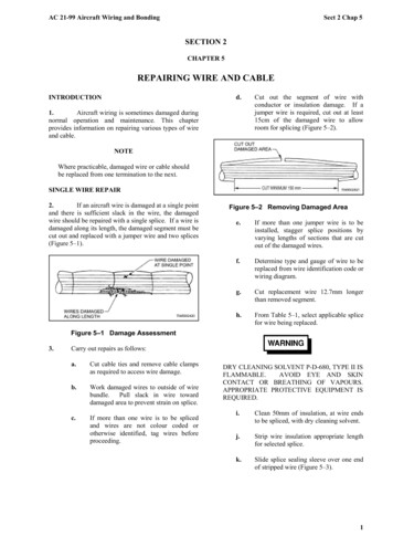
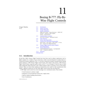
Completed Lightning Sensor BoardThe entire assembly should be housed in a waterproof container. Apiece of 3/4 inch PVC pipe works great. The photo below shows theLSU assembled into 3/4 inch PVC pipe with a tee for mounting, andthe coax cable routed through the bottom. The pipe should be longenough to fit the antenna without folding. Use RTV to hold the wirestraight inside the PVC pipe.The Interface BoardThe interface board couples the LSU with the counter board, providingpower for the LSU and isolation for the counter board. If you areassembling the counter board from scratch, then this circuitry may beincluded on the same board. Because the low side of the LSU is tied toearth ground, a potential ground loop may be created if the 1-wire busis not isolated. To prevent this, and provide a small amount of lightningprotection, an opto-isolator connects the LSU to the Counter board.This design shows a 4N49, but the selection is not critical. Current thruthe LED is limited by R3 on the LSU. The 9-volt battery provides thenecessary drive through LSU Q2 to power the LED side of the optocoupler. Because current only flows during a lightning detection, thebattery should last over 2 years.Schematic for the Interface Board
Completed Interface BoardThe Counter BoardI used a pre-built counter board from the Rain Gauge kit. Just removethe reed switch and solder wires to the pads. Otherwise, you can buildit from scratch. The rain gain board contains a DS2407 switch, which isnot used in this project. The battery and the associated steering diodemay be left out if your 1-wire bus is constantly powered and your notinterested in keeping a long-term running count of lightning strikes. The1-wire bus side should be connected to your 1-wire bus. In the photobelow a RJ-11 phone jack is crimped to a 6" twisted pair.
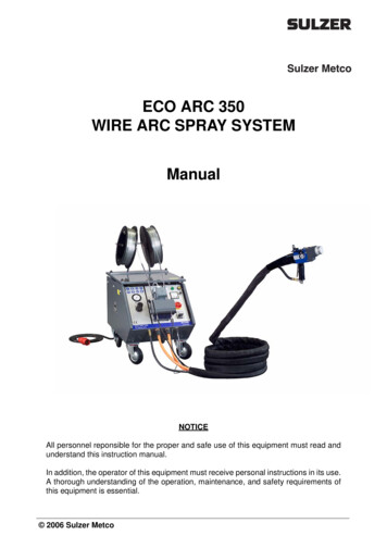
The Counter Board SchematicThe counter and interface boards can be mounted in a weather-tightenclosure in a location with easy access. Radio shack sells a weatherproof telephone wiring box that works great. It can also house the other1-wire connections.The Rain Gauge Counter Board
Installation and TestThe LSU should be connected to the interface board using a suitablelength of coax cable. Selection of the coax is not critical. I used thesmaller RG133, however standard RG-58 works fine. The shield onone end should be connected to the minus (-) side of the LSU. Theshield on the other end should be tied to a good earth ground and tothe minus(-) input on the interface board. If your using a metal pole, besure to ground it also. The earth ground is important because the LSUis measuring the EMF between its antenna and ground. It alsoprovides a path for lightning should it get a little to close.The interface board connects directly to the counter board. If thecounter board is more than a foot away, using twisted pair wiring mayhelp eliminate false triggers.
The One Wire Lightning MonitorOnce everything is connected, you’ll need software to read thecounter, such as TMEX. Launch the software and detect the 1-wiredevice. Select the counter and view the count on page 15 (same as therain gauge).Next you will need a lightning simulator. I found that a 2.99 "scripto"utility lighter, the kind with an electronic spark, works great. The areavailable at most grocery and hardware stores. Hold the lighter within afew inches of the LSU and click the sparker. You should see thecounter increment. If not, retrace your wiring and check the battery. If itstill wont count, touch a jumper across D2 on the LSU board. This willbypass the LSU and the counter should increment.An inexpensive Lightning GeneratorOnce everything checks out, install the sensor in the PVC pipe and theinterface/counter boards in a weather-tite enclosure near the LSU.Next, mount the LSU at least 5 feet above the ground. The higher thesensor, the farther away you’ll be able to detect lightning. At 10 feet,range should be between 30 to 50 miles. If your interested in just localconditions, lower heights work best.The method I have chosen to display lightning activity is to count thenumber of strikes per minute. This gives you a feeling for how activethe lightning storm is. Increasing SPMs indicate the storm is moving
closer, while decreasing values indicate the storm is moving away.Experiment with different mounting heights and display options. Pleasesend me an e-mail if you have any suggestions. You can alsosubscribe to the 1-wire weather list to share your results andimprovement suggestions.DisclaimerThis project is for experimental use only. The user assumes allresponsibilities for assembly, installation, and use. This circuit isprovided without warranty and the author makes no claim that thisdevice will work in any particular application. Having an antenna up inthe air with a cable running into your house during a thunderstormcould invite trouble. Keep a safe distance away from the display duringthunderstorms. Do not use in applications where failure or incorrectoperation could jeopardize someone's safety. Always exercise cautionwhen working outdoors during a thunderstorm. This schematic isprovided for noncommercial use only. Batteries not included.You can e-mail me at weatherprojects@mac.com if you have anyquestions or suggestions.12/29/01 2001 T. Bitson
The entire lightning detector is now also available in a kit or fully assembled form at Hobby-Boards. The Lightning Sensor Unit The lightning sensor unit performs the lightning detection. Referring to the schematic, energy from the lightning is received from the antenna, passes through the hi-gain Darlington pair, allowing current to flow through Q2 during each lightning strike. Schematic for .