Transcription
11Boeing B-777: Fly-ByWire Flight ControlsGregg F. BartleyBoeing11.111.211.311.4IntroductionSystem OverviewDesign PhilosophySystem ArchitectureFlight Deck Controls System Electronics ARINC 629Data Bus Interface to Other AirplaneSystems Electrical Power11.5Control Surface ActuationFly-by-Wire Actuation Mechanical Control11.611.711.8Fault ToleranceSystem Operating ModesControl Laws and System FunctionalityPitch Control Yaw Control Roll Control 757 TestBed Actuator Force-Flight Elimination11.911.10Primary Flight Controls System Displaysand AnnunciationsSystem MaintenanceCentral Maintenance Computer Line ReplaceableUnits Component Adjustment11.11 SummaryDefining Terms11.1 IntroductionFly-By-Wire (FBW) Primary Flight Controls have been been used in military applications such asfighter airplanes for a number of years. It has been a rather recent development to employ them in acommercial transport application. The 777 is the first commercial transport manufactured by Boeingwhich employees a FBW Primary Flight Control System. This chapter will examine a FBW PrimaryFlight Control System using the specific system on the 777 as an example. It must be kept in mindwhile reading this chapter that this is only a single example of what is currently in service in the airlineindustry. There are several other airplanes in commercial service made by other manufacturers thatemploy a different architecture for their FBW flight control system than described here.A FBW flight control system has several advantages over a mechanical system. These include: Overall reduction in airframe weight.Integration of several federated systems into a single system.Superior airplane handling characteristics.Ease of maintenance. 2001 by CRC Press LLC
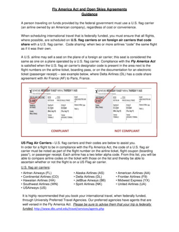
Ease of manufacture. Greater flexibility for including new functionality or changes after initial design and production.11.2 System OverviewConventional primary flight controls systems employ hydraulic actuators and control valves controlledby cables that are driven by the pilot controls. These cables run the length of the airframe from thecockpit area to the surfaces to be controlled. This type of system, while providing full airplane controlover the entire flight regime, does have some distinct drawbacks. The cable-controlled system comes witha weight penalty due to the long cable runs, pulleys, brackets, and supports needed. The system requiresperiodic maintenance, such as lubrication and adjustments due to cable stretch over time. In addition,systems such as the yaw damper that provide enhanced control of the flight control surfaces requirededicated actuation, wiring, and electronic controllers. This adds to the overall system weight andincreases the number of components in the system.FIGURE 11.1 The Primary Flight Control System on the Boeing 777 is comprised of the outboard ailerons,flaperons, elevator, rudder, horizontal stabilizer, and the spoiler/speedbrakes.In a FBW flight control system, the cable control of the primary flight control surfaces has beenremoved. Rather, the actuators are controlled electrically. At the heart of the FBW system are electroniccomputers. These computers convert electrical signals sent from position transducers attached to thepilot controls into commands that are transmitted to the actuators. Because of these changes to thesystem, the following design features have been made possible: Full-time surface control utilizing advanced control laws. The aerodynamic surfaces of the 777have been sized to afford the required airplane response during critical flight conditions. Thereaction time of the control laws is much faster than that of an alert pilot. Therefore, the size ofthe flight control surfaces could be made smaller than those required for a conventionally controlled airplane. This results in an overall reduction in the weight of the system. Retention of the desirable flight control characteristics of a conventionally controlled system andthe removal of the undesirable characteristics. This aspect is discussed further in the section oncontrol laws and system functionality. Integration of functions such as the yaw damper into the basic surface control. This allows theseparate components normally used for these functions to be removed. Improved system reliability and maintainability. 2001 by CRC Press LLC
11.3 Design PhilosophyThe philosophy employed during the design of the 777 Primary Flight Control System maintains asystem operation that is consistent with a pilot’s past training and experience. What is meant by thisis that however different the actual system architecture is from previous Boeing airplanes, the presentation to the pilot is that of a conventionally controlled mechanical system. The 777 retains theconventional control column, wheel, and rudder pedals, whose operation are identical to the controlsemployed on other Boeing transport aircraft. The flight deck controls of the 777 are very similar tothose of the Boeing 747-400, which employs a traditional mechanically controlled Primary Flight ControlSystem.Because the system is controlled electronically, there is an opportunity to include system controlaugmentation and envelope protection features that would have been difficult to provide in a conventionalmechanical system. The 777 Primary Flight Control System has made full use of the capabilities of thisarchitecture by including such features as: Bank angle protectionTurn compensationStall and overspeed protectionPitch control and stability augmentationThrust asymmetry compensationMore will be said of these specific features later. What should be noted, however, is that none of thesefeatures limit the action of the pilot. The 777 design utilizes envelope protection in all of its functionalityrather than envelope limiting. Envelope protection deters pilot inputs from exceeding certain predefinedlimits but does not prohibit it. Envelope limiting prevents the pilot from commanding the airplane beyondset limits. For example, the 777 bank angle protection feature will significantly increase the wheel forcea pilot encounters when attempting to roll the airplane past a predefined bank angle. This acts as aprompt to the pilot that the airplane is approaching the bank angle limit. However, if deemed necessary,the pilot may override this protection by exerting a greater force on the wheel than is being exerted bythe backdrive actuator. The intent is to inform the pilot that the command being given would put theairplane outside of its normal operating envelope, but the ability to do so is not precluded. This conceptis central to the design philosophy of the 777 Primary Flight Control System.11.4 System Architecture11.4.1 Flight Deck ControlsAs noted previously, the 777 flight deck utilizes standard flight deck controls; a control column, wheel,and rudder pedals that are mechanically linked between the Captain’s and First Officer’s controls. Thisprecludes any conflicting input between the Captain and First Officer into the Primary Flight ControlSystem. Instead of the pilot controls driving quadrants and cables, as in a conventional system, they areattached to electrical transducers that convert mechanical displacement into electrical signals.A gradient control actuator is attached to the two control column feel units. These units provide thetactile feel of the control column by proportionally increasing the amount of force the pilot experiencesduring a maneuver with an increase in airspeed. This is consistent with a pilot’s experience in conventionalcommercial jet transports.Additionally, the flight deck controls are fitted with what are referred to as ‘‘backdrive actuators.” Asthe name implies, these actuators backdrive the flight deck controls during autopilot operation. Thisfeature is also consistent with what a pilot is used to in conventionally controlled aircraft and allows thepilot to monitor the operation of the autopilot via immediate visual feedback of the pilot controls thatis easily recognizable. 2001 by CRC Press LLC
11.4.2 System ElectronicsThere are two types of electronic computers used in the 777 Primary Flight Control System: the ActuatorControl Electronics (ACE), which is primarily an analog device, and the Primary Flight Computer (PFC),which utilizes digital technology. There are four ACEs and three PFCs employed in the system. Thefunction of the ACE is to interface with the pilot control transducers and to control the Primary FlightControl System actuation with analog servo loops. The role of the PFC is the calculation of control lawsby converting the pilot control position into actuation commands, which are then transmitted to theACE. The PFC also contains ancillary functions, such as system monitoring, crew annunciation, and allthe Primary Flight Control System onboard maintenance capabilities.Four identical ACEs are used in the system, referred to as L1, L2, C, and R. These designations correspondroughly to the left, center, and right hydraulic systems on the airplane. The flight control functionsare distributed among the four ACEs. The ACEs decode the signals received from the transducers usedon the flight deck controls and the primary surface actuation. The ACEs convert the transducer positioninto a digital value and then transmit that value over the ARINC 629 data busses for use by the PFCs.There are three PFCs in the system, referred to as L, C, and R. The PFCs use these pilot control and surfacepositions to calculate the required surface commands. At this time, the command of the automaticfunctions, such as the yaw damper rudder commands, are summed with the flight deck control commands, and are then transmitted back to the ACEs via the same ARINC 629 data busses. The ACEsthen convert these commands into analog commands for each individual actuator.11.4.3 ARINC 629 Data BusThe ACEs and PFCs communicate with each other, as well as with all other systems on the airplane, viatriplex, bi-directional ARINC 629 Flight Controls data busses, referred to as L, C, and R. The connectionfrom these electronic units to each of the data busses is via a stub cable and an ARINC 629 coupler. Eachcoupler may be removed and replaced without disturbing the integrity of the data bus itself.11.4.4 Interface to Other Airplane SystemsThe Primary Flight Control System transmits and receives data from other airplane systems by twodifferent pathways. The Air Data and Inertial Reference Unit (ADIRU), Standby Attitude and Air DataReference Unit (SAARU), and the Autopilot Flight Director Computers (AFDC) transmit and receivedata on the ARINC 629 flight controls data busses, which is a direct interface to the Primary FlightComputers. Other systems, such as the Flap Slat Electronics Unit (FSEU), Proximity Switch ElectronicsUnit (PSEU), and Engine Data Interface Unit (EDIU) transmit and receive their data on the ARINC 629systems data busses. The PFCs receive data from these systems through the Airplane Information Management System (AIMS) Data Conversion Gateway (DCG) function. The DCG supplies data from thesystems data busses onto the flight controls data busses. This gateway between the two main sets ofARINC 629 busses maintains separation between the critical flight controls busses and the essentialsystems busses but still allows data to be passed back and forth.11.4.5 Electrical PowerThere are three individual power systems dedicated to the Primary Flight Control System, which arecollectively referred to as the Flight Controls Direct Current (FCDC) power system. An FCDC PowerSupply Assembly (PSA) powers each of the three power systems. Two dedicated Permanent MagnetGenerators (PMG) on each engine generate AC power for the FCDC power system. Each PSA convertsthe PMG alternating current into 28 V DC for use by the electronic modules in the Primary Flight ControlSystem. Alternative power sources for the PSAs include the airplane Ram Air Turbine (RAT), the 28-VDC main airplane busses, the airplane hot battery buss, and dedicated 5 Ah FCDC batteries. Duringflight, the PSAs draw power from the PMGs. For on-ground engines-off operation or for in-flight failuresof the PMGs, the PSAs draw power from any available source. 2001 by CRC Press LLC
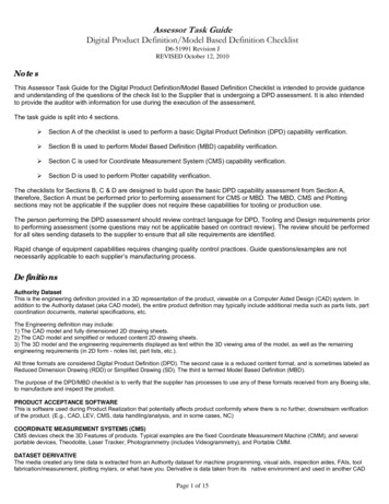
FIGURE 11.2 Block diagram of the electronic components of the 777 Primary Flight Control System, as well asthe interfaces to other airplane systems.11.5 Control Surface Actuation11.5.1 Fly-by-Wire ActuationThe control surfaces on the wing and tail of the 777 are controlled by hydraulically powered,electrically signaled actuators. The elevators, ailerons, and flaperons are controlled by two actuatorsper surface, the rudder is controlled by three. Each spoiler panel is powered by a single actuator.The horizontal stabilizer is positioned by two parallel hydraulic motors driving the stabilizer jackscrew.The actuation powering the elevators, ailerons, flaperons, and rudder have several operational modes.These modes, and the surfaces that each are applicable to, are defined below. 2001 by CRC Press LLC
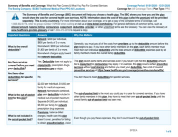
FIGURE 11.3Block diagram of the 777 Fly-By-Wire Power Distribution System.Active—Normally, all the actuators on the elevators, ailerons, flaperons, and rudder receive commandsfrom their respective ACEs and position the surfaces accordingly. The actuators will remain in theactive mode until commanded into another mode by the ACEs.Bypassed—In this mode, the actuator does not respond to commands from its ACE. The actuator isallowed to move freely, so that the redundant actuator(s) on a given surface may position thesurface without any loss of authority, i.e., the actuator in the active mode does not have tooverpower the bypassed actuator. This mode is present on the aileron, flaperon, and rudderactuators.Damped—In this mode, the actuator does not respond to the commands from the ACE. The actuatoris allowed to move, but at a restricted rate which provides flutter damping for that surface. Thismode allows
ARINC 629 busses maintains separation between the critical flight controls busses and the essential systems busses but still allows data to be passed back and forth. 11.4.5 Electrical Power There are three individual power systems dedicated to the Primary Flight Control System, which are collectively referred to as the Flight Controls Direct Current (FCDC) power system. An FCDC Power Supply .