Transcription
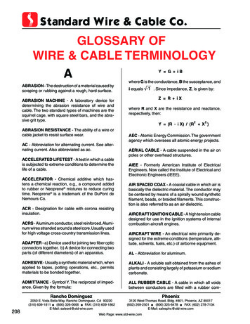
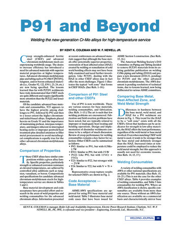
AC 21-99 Aircraft Wiring and BondingSect 2 Chap 5SECTION 2CHAPTER 5REPAIRING WIRE AND CABLEd.INTRODUCTION1.Aircraft wiring is sometimes damaged duringnormal operation and maintenance. This chapterprovides information on repairing various types of wireand cable.Cut out the segment of wire withconductor or insulation damage. If ajumper wire is required, cut out at least15cm of the damaged wire to allowroom for splicing (Figure 5–2).NOTEWhere practicable, damaged wire or cable shouldbe replaced from one termination to the next.SINGLE WIRE REPAIR2.If an aircraft wire is damaged at a single pointand there is sufficient slack in the wire, the damagedwire should be repaired with a single splice. If a wire isdamaged along its length, the damaged segment must becut out and replaced with a jumper wire and two splices(Figure 5–1).Figure 5–2 Removing Damaged Areae.If more than one jumper wire is to beinstalled, stagger splice positions byvarying lengths of sections that are cutout of the damaged wires.f.Determine type and gauge of wire to bereplaced from wire identification code orwiring diagram.g.Cut replacement wire 12.7mm longerthan removed segment.h.From Table 5–1, select applicable splicefor wire being replaced.Figure 5–1 Damage Assessment3.Carry out repairs as follows:a.Cut cable ties and remove cable clampsas required to access wire damage.b.Work damaged wires to outside of wirebundle. Pull slack in wire towarddamaged area to prevent strain on splice.c.If more than one wire is to be splicedand wires are not colour coded orotherwise identified, tag wires beforeproceeding.DRY CLEANING SOLVENT P-D-680, TYPE II ISFLAMMABLE.AVOID EYE AND SKINCONTACT OR BREATHING OF VAPOURS.APPROPRIATE PROTECTIVE EQUIPMENT ISREQUIRED.i.Clean 50mm of insulation, at wire endsto be spliced, with dry cleaning solvent.j.Strip wire insulation appropriate lengthfor selected splice.k.Slide splice sealing sleeve over one endof stripped wire (Figure 5–3).1Aircraft Technical Book Companyhttp://www.ACTechbooks.com
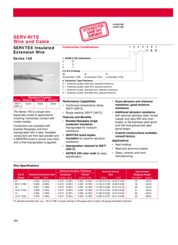
AC 21-99 Aircraft Wiring and BondingSect 2 Chap 5Table 5–1 Splice SelectionWire GaugeSplice Part NumberColour BandCrimp ToolCrimp Die26, 24, 22, 03orM22520/10-10420, 18, 103orM22520/10-10416, 14, 5-102orM22520/10-103USE ONLY HOT AIR GUN M83521/5-01 OREQUIVALENT ON FUELLED AIRCRAFTFigure 5–3 Sealing Sleeve placed on OneWire Endl.Using appropriate crimping tool anddie (Table 5–1) crimp splice to wireends (Figure 5–4)USE OF NITROGEN WITH HOT AIR GUNM83521/5-01 IN AN ENCLOSED AREA CANBE HAZARDOUS. ENSURE AREA IS WELLVENTILATED.Shrink sealing sleeve using hot air gunwith small termination reflector.Shrink middle first and move heattowards one end until sealant melts andbegins to flow out of sleeve (Figure 5–6). Repeat for other end. Allow tocool.n.Figure 5–4 Correctly Installed Crimp Barrelm.Centre sealing sleeve over crimp barrel(Figure 5–5).Figure 5–5 Sealing Sleeve Centred overCrimp BarrelFigure 5–6 Splice Sealingo.2Aircraft Technical Book Companyhttp://www.ACTechbooks.comIf installing a jumper wire, repeat stepsi to n.
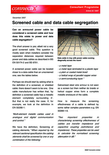
AC 21-99 Aircraft Wiring and Bondingp.Sect 2 Chap 5Work repaired wires into the bundleensuring splices remain staggered(Figure 5–7).Figure 5–8 Scored Jacket on MultiConductor CableFigure 5–7 Completed Splicesq.Replace cable clamps and cable tiesremoved for access.Figure 5–9 Damage AssessmentMULTI-CONDUCTOR CABLE REPAIR4.The following paragraphs provide details ofprocedures, components and tooling for the repair ofmulti-conductor cables.e.If more than one wire is to be splicedand wires are not colour coded orotherwise identified, tag wires beforeproceeding.f.Cut out the segment of wire withconductor or insulation damage. If ajumper wire is required, cut out at least15cm of the damaged wire to allowroom for splicing (Figure 5–10).NOTEWhere practicable, damaged cable should bereplaced from one termination to the next.5.Unshielded Cable Repair. Carry out repairsas follows:a.Cut cable ties and remove cableclamps as required to access cabledamage.WHENSCORINGCABLEJACKET,ENSURE CONDUCTOR INSULATION ISNOT DAMAGED.Figure 5–10 Removing Damaged Areab.Using a sharp blade or knife, scorecable jacket around the cable and alongthe length of the damaged area (Figure5–8).g.If more than one jumper wire is to beinstalled, stagger splice positions byvarying lengths of sections that are cutout of the damaged wires.c.Flex cable at score marks until jacketseparates.h.d.Remove jacket to gain access todamaged wires (Figure 5–9).Determine type and gauge of wire tobe replaced from wire identificationcode or wiring diagram.i.Cut replacement wire 12.7 mm longerthan removed segment.j.Select applicable splice for wire beingreplaced from Table 5–2.3Aircraft Technical Book Companyhttp://www.ACTechbooks.com
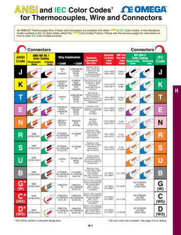
AC 21-99 Aircraft Wiring and BondingSect 2 Chap 5Table 5–2 Splice SelectionWire GaugeSplice Part NumberColour BandCrimp ToolCrimp Die26, 24, 22, 20M81824/1-1Red20, 18, 16M81824/1-2Blue16, 14, 520/5-102orM22520/10-103DRY CLEANING SOLVENT P-D-680, TYPE IIIS FLAMMABLE. AVOID EYE AND SKINCONTACT AND BREATHING OF VAPOURS.APPROPRIATE PROTECTIVE EQUIPMENT ISREQUIRED.k.Using dry cleaning solvent, clean50 mm of insulation at wire ends to bespliced.l.Strip wire insulation appropriate lengthfor selected splice.Figure 5–11 Sealing Sleeve Placed on OneWire Endm.Slide splice sealing sleeve over oneend of stripped wire (Figure 5–11).n.Using appropriate crimping tool anddie (Table 5–2) crimp splice to wireends (Figure 5–12).o.Centre sealing sleeve over crimp barrel(Figure 5-13).Figure 5–13 Sealing Sleeve Centreed OverCrimp BarrelUSE ONLY HOT AIR GUN M83521/5-01 OREQUIVALENT ON FUELLED AIRCRAFT.USE OF NITROGEN WITH HOT AIR GUNM83521/5-01 IN AN ENCLOSED AREA CANBE HAZARDOUS. ENSURE AREA IS WELLVENTILATED.Figure 5–14 Splice SealingFigure 5–12 Correctly Installed Crimp Barrel4Aircraft Technical Book Companyhttp://www.ACTechbooks.com
AC 21-99 Aircraft Wiring and Bondingp.q.Shrink sealing sleeve using hot air gunwith small termination reflector.Shrink the middle first and heattowards one end until sealant melts andbegins to flow out of sleeve (Figure 5–14).Sect 2 Chap 5NOTEWhen applying insulating tape, hands should befree of dirt and oil.s.Apply insulating tape starting 12.7 mmbefore repaired area. Wrap tape onecomplete turn around cable parallel tojacket cut line (Figure 5–16).t.Keeping tape stretched firmly, beginwrapping around cable in a singlelayer, spiral wrap, using a 50%overlap.u.Continue wrapping until cable iswrapped 12.7 mm beyond repair area.v.Terminate tape by wrapping onecomplete turn around cable, keepingtape at a right angle to axis of bundle.w.Spot tie both ends of insulating tape(Figure 5–16).x.Replace cable clamps and cable tiesremoved for access.Repeat for other end. Allow to cool.If installing a jumper wire, repeat stepsl. to p.Figure 5–15 Completed Splicesr.Work repaired wires into the bundleensuring splices remain staggered(Figure 5–15).Figure 5–16 Taping Cable Jacket6.Shielded Cable Repair. Carry out repairs asfollows:5Aircraft Technical Book Companyhttp://www.ACTechbooks.com
AC 21-99 Aircraft Wiring and BondingSect 2 Chap 5NOTEThis procedure calls for cutting all conductorsin the cable to allow installation of the repairbraid and insulation tubing.a.b.c.Cut cable ties and remove cableclamps as required to access cabledamage.Select shield repair kit according to theoutside diameter of the damaged cablejacket (Table 5–3).Figure 5–19 Wire With Damaged SectionRemovedi.Cut undamaged wires at staggeredlocations (Figure 5–20).Using a sharp blade, score cable jacketaround the cable and along the lengthof the damaged area (Figure 5–17).Figure 5–20 Undamaged Wires Cut atStaggered Locationsj.Figure 5–17 Scored Jacketd.Flex cable at score marks until jacketseparates.e.Remove jacket.f.Using small scissors or diagonal cutter,remove shield, taking care not todamage underlying wire insulation(Figure 5–18).Slide tubing and braid from shieldrepair kit, over one cable end (Figure5–21). Tape tubing and braid awayfrom repair area.Figure 5–21 Tubing and Braid Located onCable Endk.If damaged sections of wire have beenremoved ensure that the removedsections are at least 50 mm long, toallow room for splicing.l.If more than one jumper wire is to beinstalled, stagger splice positions byvarying lengths of sections that are cutout of the damaged wires.m.Determine type and gauge of wire tobe replaced from cable identificationcode or wiring diagram.n.Cut replacement wire appropriatelength to match removed segment(Figure 5–22).Figure 5–18 Damaged Multi-conductor Cableg.If wires are not colour coded orotherwise identified, tag all wiresbefore proceeding.h.Cut wires to remove damage. If asegment of damaged wire must be cutout, remove at least 50 mm totallength. (Figure 5–19). If damage is ata single point, damaged wire can becut at the point of damage.Table 5–3 Shield Repair Kit Selection6Aircraft Technical Book Companyhttp://www.ACTechbooks.com
AC 21-99 Aircraft Wiring and BondingRepair KitPart NumberSect 2 Chap 5Cable ParametersKit ComponentsNumber ofConductorsConductorSize RangeConductor SplicePart NumberSpliceQuantityShield SplicePart NumberM81824/5-1 4/5-2 -3 -4 4/5-5 orD-150-0175218-16M81824/1-22M81824/4-5M81824/5-6 orD-150-0176214M81824/1-32M81824/4-6M81824/5-7 orD-150-0177212M81824/1-32M81824/4-7M81824/5-8 orD-150-01783 or 426-24M81824/1-14M81824/4-4M81824/5-9 orD-150-01793 or 422-20M81824/1-14M81824/4-5M81824/5-10 orD-150-01803 or 418-16M81824/1-24M81824/4-6M81824/5-11 orD-150-01813 or 414-12M81824/1-34M81824/4-7o.Carry out wire splicing procedure asdetailed in paragraph 3, steps i to n.p.When all wires have been reconnected,remove 12.7 mm of cable jacket ateach end by carefully scoring aroundcable and along length to be stripped(Figure 5–17).Figure 5–22 Jumper Wire Cut to MatchRemoved SegmentFigure 5–23 Jacket Removed7Aircraft Technical Book Companyhttp://www.ACTechbooks.com
AC 21-99 Aircraft Wiring and Bondingq.Sect 2 Chap 5Slide repair braid along cable andcentre over repaired area (Figure 5–24).Figure 5–24 Repair Braid Centred OverRepair AreaFigure 5–25 Heating Repair BraidUSE ONLY HOT AIR GUN M83521/5-01 OREQUIVALENT ON FUELLED AIRCRAFT.Figure 5–26 Tubing Centred Over RepairedAreaUSE OF NITROGEN WITH HOT AIR GUNM83521/5-01 IN AN ENCLOSED AREA CANBE HAZARDOUS. ENSURE AREA IS WELLVENTILATED.r.Heat one end of the repair braid usinghot air gun fitted with appropriate sizereflector. Apply heat to theoverlapping shield area until the soldermelts and the sleeve shrinks onto thecable. Continue heating until solderflows into braid strands. Allow to coolundisturbed until solder solidifies(Figure 5–25).s.Repeat step r. for opposite end.t.Slide heat shrink tubing over repairedarea and centre (Figure 5–26).u.Heat tubing using hot air gun fittedwith appropriate size reflector. Start inthe middle and heat until tubingshrinks moving out to one end. Repeatfor other end.MIL-STD-1553 DATA BUS CABLE REPAIR7.The following paragraphs provide generalinformation on MIL-STD-1553 data bus system andthe tooling, materials, and procedures for repair of thedata bus.8.The 1553B Data Bus is a computerized andmultiplex digital data distribution system for the manyfunctions of command, control, communications, andintelligence designed for military aircraft. A twinaxcable of 78 ohms was selected to provide thetransmitted digital information with the requiredprotection from magnetic and electrostatic interferenceincluding nuclear electromagnetic pulse. Therefore,complete shielding of the pair along the transmissionpath as well as within the multi-pin connector must bemaintained.NOTEWhile the information and procedurescontained in this supplement are appropriate forrepairing MIL-STD-1553 data bus cables,aircraft specific repair procedures takeprecedence.Single Shield Cable with Solder Sleeve PrimarySplice.9.Prepare the cable using the followingprocedure:a.8Aircraft Technical Book Companyhttp://www.ACTechbooks.comRemove 31mm of cable jacket (Figure5–27).
Wire Gauge Splice Part Number Colour Band Crimp Tool Crimp Die 26, 24, 22, 20 M81824/1-1 Red M22520/5-01 or M22520/10-01 M22520/5-103 or M22520/10-104 20, 18, 16 M81824/1-2 Blue M22520/5-01 or M22520/10-01 M22520/5-103 or M22520/10-104 16, 14, 12 M81824/1-3 Yellow M22520/5-01 or M22520/10-01 M22520/5-102 or M22520/10-103 DRY CLEANING SOLVENT P-D-680, TYPE II IS