Transcription
ADT Pulse Interactive SolutionsMDC835Mini Dome CameraInstallation Guide
Chapter 1 IntroductionTable Of ContentsCHAPTER 1 INTRODUCTION . 1Overview. 1Physical Details. 2Package Contents . 4CHAPTER 2 BASIC SETUP. 5Installation. 5CHAPTER 3 CEILING MOUNTING . 5Ceiling Mounting Installation . 5CHAPTER 4 ADT PULSE ENROLLMENT. 9Wired Connection to the Gateway Using the Pulse Portal . 9Using WPS with PIN to Enroll the Camera. 12If the Camera Continually Goes Offline . 16APPENDIX A SPECIFICATIONS . 17MDC835 IP Camera . 17Regulatory Approvals . 17Copyright 2016. All Rights Reserved.Document Version: 1.0All trademarks and trade names are the properties of their respective owners.
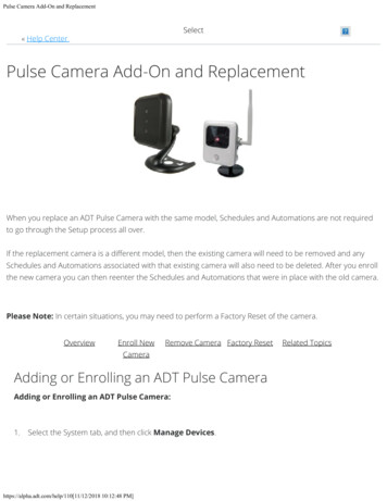
1Chapter 1IntroductionThis Chapter provides details of the IP Camerafeatures, components and capabilities.OverviewThis wireless 802.11n weather-resistant IP Camera, which comes with the IP66rated housing, has a F1.8 large aperture Lens, SONY high sensitivity imagingsensor and high power IR LED illumination, enabling it to display high qualitycolorful image in low light condition and cover the distance up to 20 meters at night.This device is also an all-in-one camera that has automatic day-night switching,built-in heater and Mechanical Pan/Tilt/Rotate orientation adjustment.The camera is intended for use in ADT Pulse.Features Lens Support. The IP Camera has the built-in F1.8 Lens with SONY Exmorhigh sensitivity 3.75 µm pixel image sensor. Dual Video Support. The IP Camera supports H.264 and MJEPG videocompression. IR LEDs Support. The built-in two infrared LEDs can provide illuminationfor up to 20 meters. Built-in Heater. The built-in Heater ensures that the camera will continueto operate even in extremely cold outdoor climates. The heater turns on whenthe temperature falls below 26.6 F (-3 C).Wireless Features1
Chapter 1 Introduction Supports 802.11n Wireless Standard. The 802.11n standardprovides for backward compatibility with the 802.11b/g wireless network. Supports WPS. Wi-Fi Protected Setup (WPS) can simplify the process ofconnecting the IP Camera to the wireless network by pin code mode via ADTpulse. Wired and Wireless Support. The IP Camera can be connected to thePulse network wirelessly. It can also be hardwired to the network.2
Chapter 1 IntroductionPhysical DetailsFront/Rear PanelFigure 1: Front/Rear PanelIR LEDsThey are used to provide illumination for night time. Pleaseensure that the two IR LEDs can be revealed in thetransparent Dome.Light SensorThis is a hardware sensor to detect lux. Please ensure thatthe light sensor can be revealed in the transparent Dome.LensNo physical adjustment is required for the lens. Pleaseensure that the lens cover remains clean.LAN portUse a standard Ethernet cable (not included) to connectthe LAN port of the supplied cable and the Pulse Gatewayor TS Base panel.Note:lPlugging in the Ethernet cable will disable the wirelessinterface. Only one interface can be active at any time.lThe Ethernet cable should only be connected ordisconnected when the camera is powered OFF.Attaching or detaching the Ethernet cable while thecamera is powered on does NOT switch the interfacebetween wired and wireless.2
Chapter 1 IntroductionPower InterfaceConnect the two wires of the supplied cable to the terminaladapter. Do not use the other terminal adapters; doing somay damage the camera.Power IndicatorOn (Green) - Power on.(Green, Amber,Off – No power.Blue)Blinking (Green) - The LED will blink during start up orwireless connection is under association.On (Blue) - Network connection is available (wired orwireless).On (Amber) - If the LED is on for 5 seconds and then turnsoff, the WPS function has failed; or the heater is active.Blinking (Amber) – The WPS function is active.Note: If the data is being transmitted via WiFi/LAN, Thecolor of the LED is blue in the mean time.Reset/WPS/Image Flip ButtonFigure 2: WPS/Reset/Image Flip Button3
Chapter 1 IntroductionWPS/Reset/The button serves three functions on the camera.Image Flip ButtonlWPS Pin Code Mode. When pressed and held for 5seconds during the Pulse enrollment process, thecamera creates an encryption-secured wirelessconnection.lReset. When pressed and held over 15 seconds, thecamera reboots and the settings are restored to defaultvalues.lImage Rotation. When the camera connected to ADTPulse, the image will turn 180 if you fast-click thisbutton twice.4
Chapter 1 IntroductionPackage ContentsThe following items are included:1.IP Camera with pigtail (DC-IN and RJ45)2.Terminal Adapter3.Wall Mount Screw Package4.L Tool (T10)5.Spice Connector4
2Chapter 2Basic SetupThis Chapter provides details of installing and configuring the IPCamera.InstallationFigure 3: Wired Network Connection1. Make the ConnectionUsing a Wired ConnectionIf you are using a wired connection to the MDC835, connecta standard Ethernet cable (not included) to the LAN portof the supplied cable of the camera and the Pulse Gatewayor Total Security (TS) Base panel.Using a Wireless ConnectionThe wireless (WPS) connection between the camera and thePulse Gateway or Total Security (TS) Base panel isperformed during the Pulse enrollment. See the followingsection for more details.5
Chapter 2 Basic SetupNOTE: The Wireless and LAN interfaces cannot be usedsimultaneously. Making a wired LAN connection disables theNOTEwireless interface.2. Power Upa. Run the AC Wire to the spice connector.b. Screw the red wire onto the positive( ) terminal of theterminal adapter.c.Screw the black wire onto the negative(-) terminalof the terminal adapter.d. Plug the terminal adapter into a power outlet.CAUTION: Only use the terminal adapter provided. Using adifferent adapter may cause hardware damage.3. Check the LEDThe Power LED will turn on briefly, and then start blinking.It will blink during startup, which will take 60 to 90seconds. After startup is completed, the Power LED shouldremain ON.4. Enroll the Camera in ADT PulseThis process is described in the later chapter.After the enrollment, please check the image orientation.You may rotate the image 180 degrees by fast-clicking theWPS/Reset/Image Flip button twice.5. Mount the CameraPlace the camera in a desired location near a power source.For mounting on the ceiling with the mounting plate, seeChapter 4 for more details.Mounting SuggestionTo get the best video quality for targets at night, make surethat the camera’s field of view does not include a foregroundobject, such as side wall or roof. Once installing on aceiling, angle the camera so that a minimal portion of thewall is visible.6
3Chapter 3Ceiling MountingThis Chapter provides details for final ceilingmounting of the IP CameraCeiling Mounting InstallationNOTENOTE: Ensure that the camera is configured andenrolled in ADT Pulse before permanentlymounting it.1. Locate an unused indoor outlet to plug into the terminaladapter. The outlet should be located as close as possibleto the location where the camera will be permanentlymounted.CAUTION: Do not plug in the terminal adapter until all theconnections are completed and the camera is fully mounted.2. Identify the location where you would like to mount thecamera. And then drill three holes on the ceiling based onthe mounting template (last page).3. Remove the sponge from the camera. And then use the L toolto remove the three screws and the bubble from the camera.5
Chapter 3 Ceiling MountingFigure 4: Removing the bubble from the Camera4. If using the anchors, insert them into the mounting holes.5. Align the three mounting holes of the camera stand with thethree holes and mount the camera stand on the ceiling usingthe provided screws.Figure 5: Ceiling InstallationNOTE: It is recommended to route the cablethrough the side opening of the mounting base.NOTE6. The camera offers 3-axis adjustments:lLoosen the tilt adjust screw to adjust the tile angle(0 70 ).lAdjust the pan angle (0 330 ) by holding the black liner.lUse the lens to rotate (0 350 ) the camera.Figure 6: Angle Adjustment6
Chapter 3 Ceiling MountingCAUTION: Do not entwine the antenna whileconnecting the LVDS cable.Figure 7: LVDS Cable7. Attach the bubble to the camera and tighten it using thethree screws.NOTE: You can use the marks for alignment whileattaching the bubble to the camera.NOTEFigure 8: Attaching the Camera7
Chapter 3 Ceiling MountingCAUTION: Make sure to tighten up the three screws in order toprevent water from the camera.CAUTION: Be careful not to let the bubble cover the lightsensor and damage the LVDS cable while attaching the bubbleto the camera.8. Connect the power cable to the terminal adapter.lScrew the red wire onto the positive( ) terminal of theterminal adapter.lScrew the black wire onto the negative(-) terminal of theterminal adapter.9. Plug the terminal adapter into a power outlet.10. Make sure the IP Camera is firmly fixed on the ceiling.11. Verify that the camera is active on the wireless networkand is recognized by Pulse.NOTE: It is recommended to let a qualifiedtechnician install the device.NOTE8
4Chapter 4ADT Pulse EnrollmentThis section provides instructions for wirelesslyenrolling the MDC835 Camera into the ADT Pulsenetwork. This process uses the Wi-Fi Protected Setup(WPS) with PIN method to wirelessly enroll theCamera to the gateway via the ADT Pulse Portal or TSInstaller App.Wired Connection to the Gateway Using the Pulse Portal1.2.3.4.Set up the Camera, as described in the previous chapter.Open a web browser and in the address bar, enter:https://Portal.ADTPulse.com.Type your Username and Password, and then click the SignIn button.Click the System tab, and then click the Manage Devicesbutton.9
Chapter 4 ADT Pulse Enrollment5.In the Manage Devices Assistant, click Cameras.6.Click the picture of the MDC835 or select it from thedrop-down list, and then click the Continue button.10
Chapter 4 ADT Pulse Enrollment7.8.9.Assign the MDC835 a unique Camera Name (usually based onthe location of the camera) in the space provided, andthen type in the camera’s MAC ID.Click the Continue button.Ensure that the camera is connected to the device portof the Gateway using the Ethernet cable. Click Continue.11
Chapter 4 ADT Pulse Enrollment10. After the Camera has connected and the button is nolonger grayed out, click Continue.11. Click Finish. The Pulse enrollment is complete.12. Disconnect the camera from the Gateway and remove frompower.13. Install the camera in its final location.Using WPS with PIN to Enroll the Camera1.2.3.4.5.Set up the camera, as described in the previous chapter.Launch an Internet browser and log in to the Pulse portalor TS installer app.Enter the Manage Devices screen using one of thesemethods:lFor the Pulse portal, select the System tab and clickManage Devices.lFor the TS installer app, click the Pulse Devices link.The Manage Devices screen displays.In the Manage Devices screen, click Cameras.Click the Add Using WPS button, located at the bottom ofthe screen.12
Chapter 4 ADT Pulse Enrollment6.7.8.9.Locate the camera’s PIN number on the label on the rearof the camera.Enter the PIN number in the WPS PIN field.Ensure that the camera is powered on and that the PowerLED is flashing green.Click the Continue button to initiate the WPS process.The following screen appears.13
Chapter 4 ADT Pulse Enrollment10. Press and hold the WPS/RESET/Image Flip button on thecamera for 5seconds to establish a wireless connection.The Power LED flashes amber as the gateway attempts toconnect to the camera. The wireless connection issuccessful when the Power LED turns solid green.NOTE: You must complete the WPS connection within 2minutes or else the process will time out. The timeremaining is displayed in the upper left portion of thescreen.11. When the Camera Details screen appears, showing that thecamera has been enrolled, assign the camera a unique name(usually based on the location of the camera) in the Namefield, and then click Save.14
Chapter 4 ADT Pulse EnrollmentThe Pulse enrollment is complete. The newly-added deviceappears in the Cameras list.12. At the top left of the screen, click Go Back.13. Wait until the Power LED and Network LED are both litsolid green/blue, and then disconnect the camera frompower.14. Install the camera in its final location. For WallMounting, refer to Chapter 4.15
Chapter 4 ADT Pulse EnrollmentIf the Camera Continually Goes OfflineIf after enrolling it the camera, it continually goes offline(Power LED blinks continually), the camera will automaticallyattempt to recover the wireless connection. If the cameracannot recover on its own, take the following measures tore-establish the Wi-Fi connection.1. Power cycle the camera.2. If the previous measure fails, move the gateway closer tothe camera, if possible.3. If the previous measure fails, press the camera’s resetbutton for15 seconds, and then re-enroll the camera intoPulse.4. If the previous measure fails, install a Wi-Fi RangeExtender model WN3000RPH-2ADPAS.16
Appendix ASpecificationsMDC835 IP CameraDimensions (DxH)4.33” x 3.62” (110mm x 92mm)LensF1.8. DFOV 75 VideoCompressionH.264 and MJPEGImage Resolution16:9 720p (1280x 720), QHD (640x360),VGA (640x480), QVGA (320x240)Mixed Mode (720p, VGA, QVGA)OperatingTemperature-40 F to 122 F (-40 C to 50 C)* If the temperature is below -40 C, thedevice will start the heater to warm upthe device, then boot up.StorageTemperature-40 F to 158 F (-40 C to 70 C)Network ProtocolTCP/IP, HTTP, HTTPS, DHCP, SMTP, FTP,UPnP, DDNS, NTP, RTP, RTCP, RTSP, SMB, DNSNetworkInterface1 Ethernet 10/100BaseT (RJ45) LANconnectionWirelessInterfaceIEEE 802.11n/802.11b/802.11g compatibleButton1 WPS/Reset/Image Flip ButtonLED1 3-color LED for Power/Network/HeaterIR LEDs2Power Adapter12V, 1.5ARegulatory ApprovalsFCC StatementThis equipment generates, uses, and can radiate radio frequency energy and, ifnot installed and used in accordance with the instructions, may cause harmfulinterference to radio communications. However, there is no guarantee thatinterference will not occur in a particular installation. If this equipment does causeharmful interference to radio or television reception, which can be determined by17
Appendixturning the equipment off and on, the user is encouraged to try to correct theinterference by one of the following measures: Reorient or relocate the receiving antenna.Increase the separation between the equipment and receiver.Connect the equipment into an outlet on a circuit different from that to whichthe receiver is connected.Consult the dealer or an experienced radio/TV technician for help.To assure continued compliance, any changes or modifications not expresslyapproved by the party responsible for compliance could void the user's authority tooperate this equipment. (Example - use only shielded interface cables whenconnecting to computer or peripheral devices).FCC Radiation Exposure StatementThis equipment complies with FCC RF radiation exposure limits set forth for anuncontrolled environment. This equipment should be installed and operated with aminimum distance of 20 centimeters between the radiator and your body.This device complies with Part 15 of the FCC Rules. Operation is subject to thefollowing two conditions:(1) This device may not cause harmful interference, and(2) This device must accept any interference received, including interference thatmay cause undesired operation.This transmitter must not be co-located or operating in conjunction with any otherantenna or transmitter.Industry Canada statement:This device complies with RSS-247 of the Industry CanadaRules. Operation is subject to the following two conditions:(1) This device may not cause harmful interference, and (2)this device must accept any interference received, includinginterference that may cause undesired operation.Ce dispositif est conforme à la norme RSS-247 d'IndustrieCanada applicable aux appareils radio exempts de licence. Sonfonctionnement est sujet aux deux conditions suivantes: (1)le dispositif ne doit pas produire de brouillagepréjudiciable, et (2) ce dispositif doit accepter toutbrouillage reçu, y compris un brouillage susceptible deprovoquer un fonctionnement indésirable.18
AppendixRadiation Exposure Statement:This equipment complies with IC radiation exposure limits setforth for an uncontrolled environment. This equipment shouldbe installed and operated with minimum distance 20cm betweenthe radiator & your body.Déclaration d'exposition aux radiations:Cet équipement est conforme aux limites d'exposition auxrayonnements IC établies pour un environnement non contrôlé.Cet équipement doit être installé et utilisé avec un minimumde 20 cm de distance entre la source de rayonnement et votrecorps.19
AppendixMounting Template20
The camera is intended for use in ADT Pulse. Features Lens Support. The IP Camera has the built-in F1.8 Lens with SONY Exmor high sensitivity 3.75 µm pixel image sensor. Dual Video Support. The IP Camera supports H.264 and MJEPG video compression. IR LEDs Support. The built-in two infrared LEDs can provide illumination for up to 20 .

