Transcription
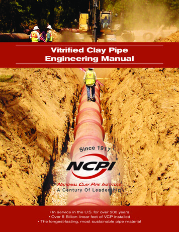
Vitrified Clay PipeEngineering Manual In service in the U.S. for over 200 years Over 5 Billion linear feet of VCP installed The longest-lasting, most sustainable pipe material
Vitrified Clay Pipe Engineering Manual 2017 by the National Clay Pipe Institute.Printed in the United States of America.
FOREWORDThe Vitrified Clay Pipe Engineering Manual has been prepared by the National Clay Pipe Institute(NCPI) and is offered by the member manufacturers of the Institute as an aid to those requiringengineering reference data applicable to the design, construction and testing of sewer systemsand other projects in which Vitrified Clay Pipe (VCP) should be used.Design and construction techniques encountered throughout the country are many and varied.Those described here are based on recognized standards and are considered sound. Technicaldata presented are considered reliable, but no guarantee is made or liability assumed. Therecommendations in this Manual should not be substituted for the judgment of a professionalengineer experienced in sanitary sewer design as to the best way of achieving specificrequirements.The Engineering Staff of NCPI and of its member companies are available to assist the reader.An electronic version of this document, including links to reference materials, is available fordownload at ncpi.org.National Clay Pipe Institute - 2017ncpi.orgForeword-1
Vitrified Clay Pipe Engineering ManualForewordThe National Clay Pipe InstituteThe National Clay Pipe Institute (NCPI), established in 1917 by clay pipe manufacturers, hasdeveloped an unmatched expertise in the use of clay pipe for gravity sanitary sewers. As aresult of this focus and decades of research and development, the organization is an invaluableresource for engineers.NCPI led the development of factory applied, flexible compression joints and the low pressureair test to verify proper installation and performance of those joints. Today, NCPI is the resourcefor technical expertise and practical experience in using VCP for open-cut as well as trenchlessinstallations. Research, development, testing and educational outreach continue to be thedriving forces for NCPI.The organization has defined best practices for, designing and installing projects with vitrifiedclay pipe and represents clay pipe manufacturers on the ASTM International (ASTM) C04Committee on Clay Pipe.HistoryFor at least 6,500 years, clay pipe has been used in sanitary sewers. The design standards andplanned functions have changed significantly over the last six millennia, but the knowledgebase acquired over that period is an important part of the development of clay pipe of the 21stcentury.Clay pipe has been used in the construction of combined sewers, storm sewers and sanitarysewers in American cities since the early 1800’s. Much of the early pipe was terra cotta andshould not be confused with today’s vitrified clay pipe. Vitrification is a critical difference.“Vitrification by definition is the progressive reduction and elimination of porosity of a ceramiccomposition with the formation of a glass phase as a result of heat treatment,” accordingto G. Bickley Remmey in his book Firing Ceramics. He goes on to say, “The firing processencompasses chemical and physical changes in the ceramic body accompanied by a loss ofporosity and a subsequent increase of density.” The ultimate purpose of firing is to achieve themechanical bonding of particles (for strength) and consolidation or reduction in porosity (e.g.,for impermeability to fluids).In 1915, almost 100-years after clay pipe was introduced in the sewers of major U.S. cities,ASTM accepted the recommendations of the C04 committee as the first tentative specificationfor sewer design and construction, designated C12, Recommended Practice for Laying SewerPipe. For the preceding 100-years there were no accepted standard practices, so the quality ofinstallation was very much determined by individual engineers and their construction teams.It is a testament to those individuals and the clay pipe manufacturers of the day that 200-yearslater some of those sewers are still in service.Foreword-2ncpi.orgNational Clay Pipe Institute - 2017
Vitrified Clay Pipe Engineering ManualForeword100 – 200 Years of Service in the U.S.(As of 2015)Years in ServiceYear Installed200 Years1815Washington, DC175 - 199 Years1829Boston, MA1850Clinton, IA1856Chicago, IL1861Cleveland, OH150 - 174 Years125 – 149 Years100 – 124 YearsLocationPhiladelphia, PA1866New York, NY1868Erie, PA1869Grand Rapids, MI1870Hartford, CT1872Indianapolis, IN1873Los Angeles, CAPortland, OR1874Lawrence, KS1875Baltimore, MDPortland, ME1876San Francisco, CASt. Joseph, MOJacksonville, FLAlbany, GA1877Davenport, IABucyrus, OHKansas City, MONew Bedford, MA1878Omaha, NE1879Camden, NJProvidence, RIMemphis, TNNashville, TNParkersburg, WV1880Rome, GASioux City, IAFargo, NDNapa, CARockford, ILRed Wing, MNDallas, TXSacramento, CATerre Haute, INReno, NVDenver, COWoodland, CA1881Kalamazoo, MI1884Le Mars, IA1888Salt Lake City, UT1890San Jose, CA1892Phoenix, AZMassillon, OH1895Highlands, NJAtlanta, GA1904New Castle, DE1915Seattle, WANational Clay Pipe Institute - 2017ncpi.orgSt. Louis, MONew Haven, CTRaleigh, NCSt. Paul, MNSanta Cruz, CAForeword-3
Vitrified Clay Pipe Engineering ManualForewordThe National Clay Pipe Institute and its member companies are proud of their history as earlyleaders in the acceptance of and participation in ASTM. More than a century of workingwith the engineering community has led to the development of stringent standards for themanufacture, testing and installation of VCP sanitary sewer pipe. Clay pipe manufacturers todayprovide a pipe system that is leak-free resulting in the most sustainable and longest-life sanitarysewer product available.For more information about the history of sewers, visit sewerhistory.org.AcknowledgementsThe National Clay Pipe Institute wishes to acknowledge the following subject matter experts andmembers of the NCPI Technical Services Committee who have contributed to this edition, bothindividually and collectively.Veronica Alvarez, EITLewis BertalottoJeff Boschert, P. E.Richard BrandtRudy BrandtJohn ButlerKent CarlsonDavid GillJeremy Haskins, P. EAmster HowardSteve Matheny, P. E.Todd McClaveJoe Parker, PMPGarrett RichardsonEd SikoraLarry G. TolbyBryan VansellTera ArthurMichelle HimselWe also appreciate the efforts of the many others who generously gave their time and talentthroughout the development of this manual.Foreword-4ncpi.orgNational Clay Pipe Institute - 2017
Vitrified Clay Pipe Engineering ManualTable of ContentsChapter 1: Vitrified Clay PipeProperties Pipe Specification Considerations Manufacturing Process Perforated Pipe Vitrified Clay Pipe Specification & Testing StandardsChapter 2: Gravity Sewer DesignPlanning and Layout Curvilinear Sewer Design Selecting Pipe Sizes Manning’s “n” CoefficientChapter 3: Corrosion, Solvent‐Based Chemicals, Abrasion &High Temperature Applications in Sanitary SewersInternal and External Corrosion Abrasion Resistance Solvent BasedChemical Applications High Temperature ApplicationsChapter 4: Structural Analysis of Rigid Conduits, UndergroundUsing the Marston Load Equations for Computing Trench and Tunnel Loads Modified Marston Equation When CLSM Bedding is Utilized Concentratedand Distributed Superimposed Dead and Live Loading EquationsChapter 5: Trench Load TablesChapter 6: Structural Design of Rigid Conduits, UndergroundRigid Pipe Bearing Strength Effect of Trench Width Allowable Beddingand Backfill Materials Haunch Support Bedding Classes and Load Factors Design Factor of SafetyChapter 7: Open Trench ConstructionExcavation Trench Shoring Foundation Support Pipe Installation Compaction of BackfillChapter 8: Jacking Pipe & Trenchless Installation MethodsVitrified Clay Jacking Pipe Slurry Microtunneling Static Pipe Bursting Pilot Tube MethodChapter 9: Construction of Special StructuresManholes Pipe Manhole Connections Terminal Cleanout StructuresChapter 10: Residential Building SewersLateral Sewer Installation Tapping an Existing LineChapter 11: Inspection & TestingInspection Tools Air and Hydrostatic Infiltration Acceptance TestingChapter 12: Operations & MaintenanceSewer Cleaning Hydro-Mechanical ToolsGlossary of TermsIndexFor the most up-to-date information and live links to related materials,see our manual on line at ncpi.org.
CHAPTER 1: VITRIFIED CLAY PIPEFigure 1-1: Modern Vitrified Clay Pipe (VCP) with factory-applied, compression joints, which “shall notleak,” per ASTM C425.PropertiesVitrified Clay Pipe (VCP) is uniquely suited for gravity sanitary sewers and is the longest lastingsewer pipe available. No other pipe material can match the properties or deliver the long-termvalue of VCP.Vitrified Clay Pipe attributes: Rigid Strength Flexible Watertight Joints Sustainable InertRigid StrengthVCP is categorized as a rigid conduit, which means it hasinherent structural strength in the pipe itself. The commonmethod to determine structural strength is a three-edgebearing test, which is measured in pounds of load per linearfoot of pipe length. Three-edge bearing capacitiesincrease with larger pipe diameters. Minimum strengthsNational Clay Pipe Institute - 2017ncpi.orgFigure 1-2: Three-edge bearing testing forinherent structural strength.Chapter 1-1
Vitrified Clay Pipe Engineering ManualVitrified Clay Pipeper pipe diameter are included in the standard ASTM C700 Standard Specification for VitrifiedClay Pipe, Extra Strength, Standard Strength, and Perforated.Flexible Watertight JointsNominal Diameter Deflection of Pipe,VCP compression joints shall not leak in(inches)inches/linear ft.accordance with ASTM C425 Standard3 to 121 2Specification for Compression Joints for Vitrified15 to 243 8Clay Pipe and Fittings. The joint test for VCP27 to 361 4includes subjecting an assembled deflected39 and 423 16joint to a 10-ft head of water pressure with ashear load applied. The pipe joint is deflected to481 8simulate a curvilinear alignment and the appliedTable 1-1: Joint Deflection limitsshear force simulates settlement and lack ofproper support. The minimum shear load applied to the unsupported pipe end is 150-poundsper inch of nominal diameter. With all of these loads applied for a total test period of 1 hour,the joint “shall not leak.” VCP compression joints are designed to allow angular deflection whileretaining joint integrity. See Table 1-1 for the limits of joint deflection and page 2-4 for designingcurvilinear sewers with deflected joints.Figure 1-3: Compression joint test simulates joint performance under conditions of shear load and angular deflection.SustainableVitrified Clay Pipe is the most sustainable sewer pipe manufactured today. The documentedlifecycle of VCP, coupled with naturally occurring, abundant raw materials makes it the mostsustainable pipe product ever made.The raw materials for the manufacture of VCP are clays and shales. These earthy mineralaggregates are the end products of nature’s weathering forces.Chapter 1-2ncpi.orgNational Clay Pipe Institute - 2017
Vitrified Clay Pipe Engineering ManualVitrified Clay PipeVCP manufactured by the member companies of National Clay Pipe Institute (NCPI) has beenindependently certified as environmentally friendly based on an ISO 14001-compliant life cycleassessment. This review included critical evaluation of the raw materials, sourcing, manufactureand expected product lifecycle as they impact human health and the environment over both theshort and long term. To see the scorecard from this assessment, visit the sustainability page ofthe NCPI website (ncpi.org).InertThrough centuries, soluble and reactive minerals havebeen leached from rock and soil, leaving an inert material.This chemically inert material is transformed into a dense,hard, homogeneous clay body through firing in kilns attemperatures of about 2000 F (1100 C). “Vitrification”occurs as the clay mineral particles become mechanicallybonded into an inert, chemically stable compound,integrally bonded by its very nature.VCP will not rust, corrode, shrink, elongate, bend,deflect, erode, oxidize or deteriorate over time.Figure 1-4: Firing at about 2000 F (1100 C) iscritical to achieving vitrification which creates asolid pipe body.Pipe Specification ConsiderationsE ach municipality has its own set of special challenges, but there are some universal concernsthat should be addressed when specifying any pipe material for sanitary sewers. Life expectancy: No other pipe material can match the 200-years of proven service life in theUnited States. Chemical attack: VCP is inert and therefore resistant to internal and external attack fromsolvents, acids, alkalis, gases, etc. Flow characteristics: Low friction coefficient. Structural integrity: Inherent load bearing capacity. Joint tightness: Factory applied flexible compression joints that “shall not leak.” Abrasion resistance: Exceptional resistance to abrasion and scour. Availability: Available in a full range of sizes, fittings and adapters. Environmental impact: No other pipe material can come close to the natural environmentallyresponsible credentials of VCP. Economics: Best total value considering cost of material, installation, maintenance anduseful life. Durability.National Clay Pipe Institute - 2017ncpi.orgChapter 1-3
Vitrified Clay Pipe Engineering ManualVitrified Clay PipeManufacturing ProcessVitrified Clay Pipe is one of man’s mostenduring materials. Manufacturers blendspecially selected clays and shales to developthe inherent strength and load bearingcapacities of the pipe. The principal steps inthe manufacture of clay pipe are: Mining Grinding Extruding Drying Firing Testing the Pipe and JointFigure 1-5: Modern manufacturing methods enable production oflarger diameter pipe.To see a video of the VCP Manufacturing process from the How It’s Made Science Channelepisode, visit our YouTube channel.MiningOnly specialized clays, found in hydrous alumina silicates, are suitable for the manufacture ofVitrified Clay Pipe. These clays must have an appropriate level of plasticity (essential for formingthe pipe), suitable vitrification properties and stability at high temperatures (to achieve thedesired strength during firing). Laboratory tests determine that all raw materials used meetthese qualifications and ensure that the resultant pipe meets the rigorous standards of ASTM.GrindingThe clay mixture is ground in heavy,perforated metal pans by largecrushing wheels. The mixture is thensent through fine, heated, vibratingscreens to assure proper particle size.ExtrudingGround raw materials aremixed with water in a pug mill.This material is forced through avacuum, de-airing chamber toproduce a smooth, dense mixture.The moistened clay is extruded underhigh pressure to form the pipe.Because the pressure is extreme,voids and laminations are not aconcern in modern VCP.Chapter 1-4Figure 1-6: More powerful extrusion equipment produces stronger pipe bodiesand longer pipe lengths.ncpi.orgNational Clay Pipe Institute - 2017
Vitrified Clay Pipe Engineering ManualVitrified Clay PipeDryingThe pipe is transferred to large, heated drying roomsto remove moisture. Drying time can vary based onthe size of the pipe and the level of ambient humidityFiringThe temperature in the kiln is gradually increased toapproximately 2000 F (1100 C). The first phase offiring must take place slowly so that the shape of thepipe is set before the ramp-up to the highertemperatures required for vitrification. At the highesttemperatures the interior portions of the pipe bodyare almost liquefied to create the solid ceramicstructure. Cooling also has to happen in a controlled,slow process to prevent damage. Firing times vary byraw materials and pipe size.Figure 1-7: Drying rooms capture excess heat from thekilns to help make VCP the most environmentallyresponsible sanitary sewer pipe product.Testing the Pipe & JointEvery pipe exiting the kiln is visually and physicallyinspected. Representative samples from each firingare tested for bearing strength (in accordance withASTM C700 Standard Specification for VitrifiedClay Pipe, Extra Strength, Standard Strength, andPerforated). The final test per ASTM C425 StandardSpecification for Compression Joints for Vitrified ClayPipe and Fittings includes shear load, deflection andhydrostatic pressure to simulate the most extremeconditions in the field.Figure 1-8: Aggressive testing of the joint ensureslong-term, leak-free performance.Perforated PipePerforated clay pipe are used ina variety of drainage applicationsincluding leachate detection andtransmission. Normal use requiresthat the pipe be installed on acontrolled grade with the perforationsplaced down. The surroundingmaterials should be properly sized toprevent migration of fines or blockageFigure 1-9: Perforated clay pipe is an environmental alternative forof the perforations. A filter fabric which drainage applications.restricts the passage of fines may berequired in certain installations. Refer to ASTM C700 Standard Specification of Vitrified Clay PipeExtra Strength, Standard Strength, and Perforated, and ASTM C12 Standard Practice for InstallingVitrified Clay Pipe Lines.National Clay Pipe Institute - 2017ncpi.orgChapter 1-5
Vitrified Clay Pipe Engineering ManualVitrified Clay PipeVitrified Clay Pipe ASTM Specification & Testing StandardsASTM C12Standard Practice for Installing Vitrified Clay Pipe LinesASTM C301Standard Test Methods for Vitrified Clay PipeASTM C425Standard Specification for Compression Joints for Vitrified Clay Pipe and FittingsASTM C700Standard Specification for Vitrified Clay Pipe, Extra Strength, Standard Strength,and PerforatedASTM C828Standard Test Method for Low-Pressure Air Test of Vitrified Clay Pipe LinesASTM C896Standard Terminology Relating to Clay ProductsASTM C1091Standard Test Method for Hydrostatic Infiltration Testing Of Vitrified Clay Pipe LinesASTM C1208/1208M Standard Specification for Vitrified Clay Pipe and Joints for Use in Microtunneling,Sliplining, Pipe Bursting, and TunnelsChapter 1-6ncpi.orgNational Clay Pipe Institute - 2017
CHAPTER 2: GRAVITY SEWER DESIGNFigure 2-1: Sample plan and profile illustrationPlanning and LayoutSewer PlanningSufficient lead time to formulate economic proposals, secure approvals, arrange financing,design, construct and place in operation the necessary sewers to carry domestic, commercialand industrial wastewater from a community to a point of treatment is required for projects.Most agencies have Sewer System Master Plans in place to be used in the design of pipe sizingand locations.Design PeriodA design period must be chosen and sewer capacity planned that will be adequate. Populationand land use changes for more than 20 years into the future are sometimes difficult to predictand plan. However, when planning, designing, financing and construction are compared to therelatively minor additional cost of providing extra capacity, a minimum design life of 50-yearsshould be considered and when possible, a design life of 100-years or more is recommended.Planners should design for ultimate development where special conditions exist such asremote areas near the boundary of a drainage area. Also to be considered are areas wherespecial construction, such as pump stations and inverted siphons may be required. The cost ofadditional capacity is minimal compared to the cost of relief lines installed at a later date.Mainline sewers should be designed for the population density expected in the areas served,since the quantity of domestic sewage is a function of the population and of water consumption.Trunk and interceptor sewers should be designed for the tributary areas, land use and theNational Clay Pipe Institute - 2017ncpi.orgChapter 2-1
Vitrified Clay Pipe Engineering ManualGravity Sewer Designprojected population. For these larger sewers, past and future trends in population, water useand sewage flows must be considered. The life expectancy of the pipe is critical. Clay pipe has ademonstrated life expectancy in excess of 200 years.Design FlowsA sanitary sewer has two main functions:1. to carry the maximum design flow, and2. to transport suspended solids so that deposits in the sewer are kept to a minimum.It is essential therefore that the sewer has adequate capacity for the maximum design flow andthat it function properly at minimum flow as well.Maximum design flow determines the hydraulic capacity of sewers, pump stations, andtreatment plants. Minimum flows must be considered in design of sewers and inverted siphonsto insure reasonable cleansing velocities.Extraneous FlowsSanitary sewer design quantities should include consideration of the various non-sewagecomponents, which can become a part of the total flow. These non-sewage componentshave been greatly reduced as sanitary sewers have been separated from storm sewers, but aconsideration factor for these flows is still seen as advisable.The cost of transporting, pumping and treating sewage obviously increases as the quantity offlow delivered to the pumps or treatment facility increases. Thus, extraneous flow should beeliminated to the extent possible by proper design and construction practices and adequatelyenforced connection regulations.InflowA very few illicit roof drains connected to the sanitary sewer can result in a surcharge of smallersewers. For example, a rainfall of 1 in. per hour on 1,200 ft2 of roof area, would contribute morethan 12 gpm.Connection of roof, yard and foundation drains to sanitary sewers should be legally prohibitedand steps taken to eliminate them. Most municipalities have now enacted, or are in the processof enacting laws to accomplish this. Water from these sources and surface run off should bedirected to a storm drainage system.Tests indicate that leakage through manhole covers may be from 20 to 70 gpm with a depth of1 in. of water over the cover. Such leakage may contribute amounts of storm water exceedingthe average sanitary flow.InfiltrationProminent sources of excessive infiltration can be poorly constructed manholes and/orconnections and improperly laid house laterals. In a given system, laterals frequently have atotal length greater than the collecting system. House connections should receive the samespecifications, construction and inspection as public sewers.Chapter 2-2ncpi.orgNational Clay Pipe Institute - 2017
Vitrified Clay Pipe Engineering ManualGravity Sewer DesignPrior to 1972 and the passage of the Clean Water Grant Act, sewer designers allowed higheramounts of infiltration to aid in transporting solids. “Dilution is the Solution to Pollution” was thephrase used to illustrate the design theory of the time. The cost involved in treating infiltrationin modern systems means that it must now be prevented.Advantages of Flexible Compression JointsProbably the largest misconception about VCP surrounds the jointing system. VCP is the mostwidely used pipe material for gravity sanitary sewer pipe over the last few centuries. As a result,many people think of the early field-made joints from the 1900’s and not the factory-madeflexible compression joints that were first introduced in the late 1950s. The problems with theold jointing system were twofold. The first issue was a leaky joint and the resultant root intrusionand material loss outside the pipe both affecting structural integrity of a pipeline. The secondwas created by having a joint incapable of adjusting to minor movement after installation. Whilecement mortar, oakum, and asphaltic joints are a thing of the past there are many miles ofpipelines with this antiquated joint system still in service.Figure 2-2: Polyurethane (left) and O-ring and polyester (right) flexible compression joints.Flexible compression joints conforming to ASTM C425provide a tight and flexible joint whether the seweris above or below ground water. Modern, flexiblecompression joints use polyester or polyurethanematerials and are factory applied to both the bell andspigot of every pipe (see Figure 2-2). Another jointingsystem option is plain end pipe barrels joined with rubbercompression couplings with stainless steel tighteningbands (see Figure 2-3). All of these jointing systems allowFigure 2-3: Rubber compression couplings withthe clay pipe to shift or move with any minor changes instainless steel tightening bands.earth conditions without damaging the pipe. This providesa measure of forgiveness during installation and for the life of the line.National Clay Pipe Institute - 2017ncpi.orgChapter 2-3
Vitrified Clay Pipe Engineering ManualGravity Sewer DesignCurvilinear SewersThe factory applied joints of modern VCP pipe are designed to allow some angular deflectionwhile retaining joint integrity. ASTM C425 prescribes the limits of joint deflection as shown inTable 2-1. A smaller curve radius can be created using shorter lengths of pipe.Radius of Curvature & Angle of DeflectionPipe Diameter(inches)Maximum DeflectionIn./LFAngle ΘEquationfor r*Minimum Radius of Curvature (r*)Pipe Length L (feet)46810r 24(L)96144192----(1.8 )r 32(L)1281922563201/4(1.2 )r 48(L)19228838448039 – 423/16(0.9 )r 64(L)256384512640481/8(0.6 )r 96(L)3845767689603 – 121/2(2.4 )15 – 243/827 – 36* r Minimum radius in feetTable 2-1: Radius of Curvature & Angle of DeflectionThe equation for use in determining radius, deflection angle per joint or the length of pipe in feetcan be stated as follows:r (360 /θ)(L/2π)The equation for determining the distance each pipe section needs to be deflected from astraight line (measured in inches) can be stated as:Δd tan θ (L)(12)Where:r Radius of the curved sewer in feetθ Deflection angle per jointL Length of pipe in feetΔd Deflection measured in inches per jointChapter 2-4ncpi.orgNational Clay Pipe Institute - 2017
Vitrified Clay Pipe Engineering ManualGravity Sewer DesignExample 2-1: Finding the Maximum Pipe LengthThe planned curve of a street and location of other utilities has tentatively been plannedto call for a 125 foot radius. The service demand in this area will require an 8-inch pipe.Referring to Table 2-1, the maximum allowable angular deflection for 8-inch pipe is 2.4 .r (360 /θ)(L/2π)125 (360 /2.4 ) (L/2π)L (125)(2.4)(2π)/360L 5.24’A standard 5 foot pipe length should be used.Example 2-2: Finding Angle of Deflection for Each PipeIf the design radius of the proposed 15-inch diameter sewer will be 220 feet, determinethe deflection angle of each piece of pipe.Determine that the design radius of 220 feet is larger than the minimum prescribed inTable 2-1: r 32(6) 192.r (360 /θ)(L/2π)220 (360 /θ)(6/2π)Θ (360)(6)/(220)(2π)Θ 1.56 For ease of installation, determine the distance each 6-foot length of pipe needs to bedeflected from a straight line in inches.Δd tan θ (L)(12)Δd tan 1.56 (6) (12)Δd 1.96”National Clay Pipe Institute - 2017ncpi.orgChapter 2-5
Vitrified Clay Pipe Engineering ManualGravity Sewer DesignFlow MonitoringA sewer flow-monitoring program is necessary to determine when existing sewers will reachhydraulic design capacity. Monitoring methods vary from high water markers that recordmaximum depths to hand held mechanical tools or electronic devices. With a history of flowdata, projections can forecast the year the peak flow will reach the design capacity of the sewer.Sewer line modeling computer programs are available to analyze existing systems and establishquantities for the design of relief sewers.Basic Premises for Calculating Flow in SewersThis section on hydraulics of sewers deals only with uniform flow. Standard hydraulic handbooksshould be consulted for special conditions.Since the flow characteristics of sewage and water are similar, the surface of the sewage will seekto level itself when introduced into a channel with a sloping invert. This physical phenomenoninduces movement known as gravity flow. Most sewers are of this type.The flow in a pipe with a free water surface is defined as open channel flow. Steady flow means aconstant quantity of flow and uniform flow means a steady flow in the same size conduit with thesame depth and velocity. Although these conditions seldom occur in practice, it is necessary toassume uniform flow conditions in order to simplify the hydraulic design.There are times when sewers become surcharged, encounter obstacles requiring an invertedsiphon or require pumping. Under these conditions the sewer line will flow full and be underhead or internal pressure.The Flow Characteristics Diagram (Figure 2-4) demonstrates the theory and terminology appliedto flow in open channels. To simplify the diagram, all slopes are subcritical and it is assumed thatFigure 2-4: Flow Characteristics theory and terminology illustratedChapter 2-6ncpi.orgNational Clay Pipe Institute - 2017
Vitrified Clay Pipe Engineering ManualGravity Sewer Designat point D a constant supply of water or sewage is being supplied. Between D and E the slopeof the conduit is greater than is required to carry the water at its initial velocity, and is greaterthan the retarding effect of friction, which causes acceleration to occur. At any point between Eand F, the potential energy of the water equals the loss of head due to friction and the velocityremains constant. This is uniform flow. Between F and G the effect of downstream conditionsare causing a decrease in the velocity.The Hydraulic ProfileThree distinct slope lines are commonly referred to in hydraulic design of sewers as shown inFigure 2-4.1. T he Slope of the Invert of the Sewer. This is fixed in location and elevation by construction.Except in rare cases, the invert slopes downstream in the direction of flow.2. T he Slope of the Hydraulic Gradient (H.G.). This is sometimes referred to as the water surface.In open channel flow, this is the top surface of
National Clay Pipe Institute - 2017 ncpi.org Chapter 1-1 Properties Vitrified Clay Pipe (VCP) is uniquely suited for gravity sanitary sewers and is the longest lasting sewer pipe available. No other pipe material can match the properties or deliver the long-term value of VCP. Vitrified Clay Pipe attributes: Rigid Strength