Transcription
Link BudgetCalculationTraining materials for wireless trainersWednesday, March 5, 14This 60 minute talk is about estimating wireless link performance by using link budget calculations. It also introduces the Radio Mobile linkdesign tool.Version 1.5 by Rob, @2009-11-23Version 1.7 by Carlo, @2010-01-13 (in Pune)Version 1.8 by Rob, @2010-02-28Version 1.9 by Rob, @2010-03-02Version 1.10 by Rob, @2010-03-12Version 1.12 by Carlo, @2011-03-22Version 1.13 by Carlo, @2011-03-23 - corrected a mistake of 1dB in the Lfs in slides 11 to 14version 1.15 by Ermanno, some changes in formulas and corrections in slides
Goals‣ To be able to calculatehow far we can go withthe equipment we have‣ To understand why weneed high masts for longlinks‣ To learn about softwarethat helps to automatethe process of planningradio links2Wednesday, March 5, 14
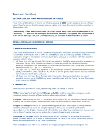
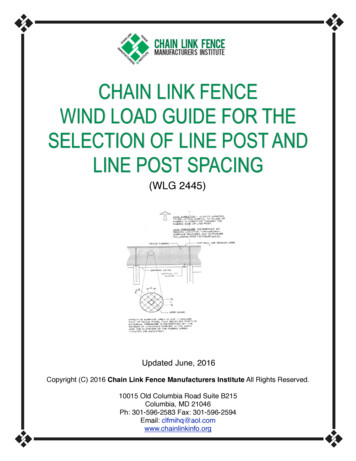
Free space loss‣ Signal power is diminished by geometric spreading of thewavefront, commonly known as Free Space Loss.‣ The power of the signal is spread over a wave front, the areaof which increases as the distance from the transmitterincreases. Therefore, the power density diminishes.Figure from http://en.wikipedia.org/wiki/Inverse square3Wednesday, March 5, 14A light bulb analogy will help understand this. If we watch the quantity of light shed over a piece of paper, we willnotice that this diminishes as we take it further away from a light bulb. This is a purely geometric phenomenon, ithappens even in a vacuum where there is nothing that can absorb the em radiation. That is why it is called freespace loss. An even better term would be “geometric spread loss”
Free Space Loss (@2.4 GHz)‣ Using decibels to express the loss and using 2.4 GHz as thesignal frequency, the equation for the Free Space Loss is:Lfs 100 20*log10(d)‣ .where Lfs is expressed in dB and d is in kilometers.4Wednesday, March 5, 14The log in this formula is in base 10.It is quite easy to use this simple formula, because the result is: 100dB (for 1 km), plus 20 dB for every time youmultiply the distance by 10. (10 km - 120dB, 100 km- 140dB, etc.).Then if you remember that log(2) 0.3, you simply add 20*0.3 6dB every time you double the distance, e.g.1km - 100dB2km - 106dB4km - 112dB8km - 118dB10km - 120dB20km - 126dB40km - 132dB80km - 138dB100km - 140dBand so on.
Free Space Loss (any frequency)‣ Using decibels to express the loss and at a generic frequencyf, the equation for the Free Space Loss is:Lfs 92,45 20*log(d) 20*log(f)‣ .where Lfs is expressed in dB, d is in kilometers and f is inGHz.5Wednesday, March 5, 14The formula in the previous slide is a particular case of this one, obtained making f 2.4 Ghz in this formula.
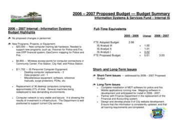
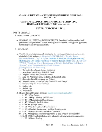
3816Wednesday, March 5, 14This graph show the free space path loss for distances up to 40 km, for both 2.4 and 5.3 GHz.Hint: if the frequency used is in the range of 5 GHz (instead of 2.4GHz) you have to add 6 dB to the loss toobtain the right result.
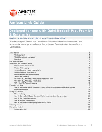
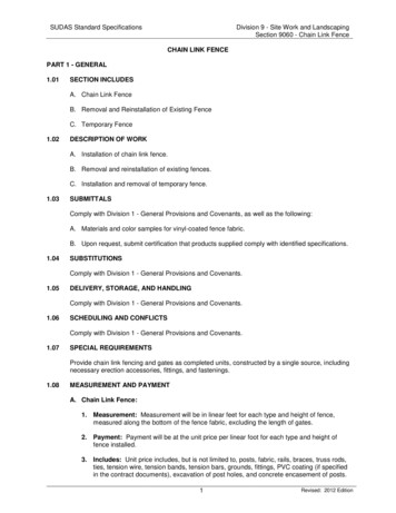
Power in a wireless systemantennaTxradiocableantennapath losscableRxradioEIRPTx powerdBmRx powerMarginRx sensitivitydistance7Wednesday, March 5, 14This graph shows the relative amount of gains and losses as well as the absolute power at each point in awireless link.The transmitter provides some amount of power. A small amount is lost in attenuation between the transmitterand the antenna. The antenna then focuses the power, providing a gain. At this point, the power is at themaximum possible value for the link. This power is called EIRP (Equivalent Isotropic Radiated Power). Mostregulators impose a limit on the maximum allowable value of EIRP in a given country.Then there are free space and environmental losses (which together form the path loss), which increase with thedistance between the link endpoints. The receiving antenna provides some additional gain. Then there is a smallamount of loss between the receiving antenna and the receiving radio.If the received amount of power at the far end is greater than the receive sensitivity of the radio, by a certainmargin M, then the link is possible. The value of M will determine the reliability of the link, a good starting pointis to have at least 10 dB margin. For critical links, it is better to strive for a 20 dB margin.
Link budget‣ The performance of any communication link depends on the qualityof the equipment being used.‣ Link budget is a way of quantifying the link performance.‣ The received power in an wireless link is determined by threefactors: transmit power, transmitting antenna gain, andreceiving antenna gain.‣ If that power, minus the free space loss of the link path, is greaterthan the minimum received signal level of the receiving radio,then a link is possible.‣ The difference between the minimum received signal level and theactual received power is called the link margin.‣ The link margin must be positive, and should be maximized (shouldbe at least 10dB or more for reliable links).8Wednesday, March 5, 14Do not confuse the link budget with the cost to obtain the equipment! We are not dealing with money here butwith dB.The link budget reflects the impact of different variables in the ultimate power that reaches the receiver.Keep in mind that the receiver sensitivity is strongly dependent on the transmission rate: the higher thetransmission ratethe higher the receiver power required for acceptable performance.If one cannot obtain an acceptable margin at a given transmission rate it might be required to work at a lowertransmission rate.The free space loss applies when there is a completely unobstructed path between the transmitter and thereceiver, with clearance of at least 60% of the first Fresnel Zone.Partial obstruction of the 1st Fresnel Zone or the presence of walls or other objects will cause additional lossesto be added to the free space loss to calculate the total path attenuation.
9Wednesday, March 5, 14Here is a example of a manufacturer’s data sheet showing the transmit power and receive sensitivity at variousmodulations and data rates. A data sheet is required for any serious outdoor work, and some data sheets aremore complete than others. Avoid manufacturers who do not publish the detailed specifications of theirequipment.Note that the minimum RSL is dependent upon rate, and the 1 Mbps rate is used for maximum range. TX poweris usually also rate dependent, but manufacturers rarely indicate this.As the received signal drops, devices will automatically reduce their speed to attempt to maintain a stable link.Note that the manufacturer specifies the frequency range from 2412-2462 MHz. The spectrum usage of eachchannel is 20 MHz, and the manufacturer is referring to the center frequency.
Example link budget calculationLet’s estimate the feasibility of a 5 km link, with one accesspoint and one client radio.The access point is connected to an antenna with 10 dBigain, with a transmitting power of 20 dBm and a receivesensitivity of -89 dBm.The client is connected to an antenna with 14 dBi gain, witha transmitting power of 15 dBm and a receive sensitivity of-82 dBm.The cables in both systems are short, with a loss of 2dB ateach side at the 2.4 GHz frequency of operation.10Wednesday, March 5, 14
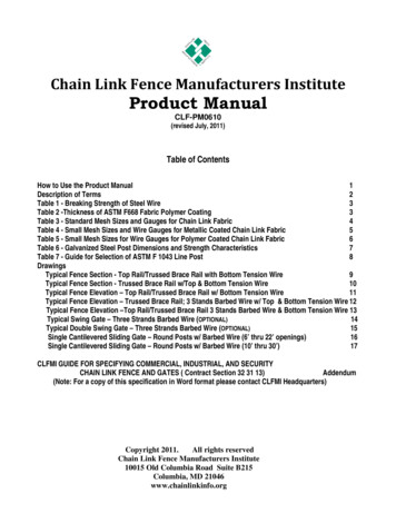
AP to Client linkantenna 10 dBi 20 dBmTxradioantennacable-2 dB EIRP 14 dBipath losscable-114 dB @ 5 km-2 dBRxradioTx powerdBm?Rx powerMarginRx sensitivity-82 dBmdistance11Wednesday, March 5, 14Here is the graph from the previous slide, with values filled in for the AP and client.
Link budget: AP to Client link -20102142dBmdBidBdBidB40 dB-114 dB(TX Power AP)(Antenna Gain(Cable Losses(Antenna Gain(Cable LossesAP)AP)Client)Client)Total Gain(free space loss @5 km)-74 dBm (expected received signal level)--82 dBm (sensitivity of Client)8 dB(link margin)12Wednesday, March 5, 14The AP to Client link is possible, but below 10 dB. This link could be improved.Remember that Free Space Loss is different than the link budget. FSL refers to the loss due to geometric spreading of signal in free space,while the link budget calculation will take the FSL into account to determine whether a link is feasible.Ask to participants how the link margin can be improved. Comment on the answers; they may suggest use of higher gain antennas,shorter/better cables, higher TX power, better receiver, or amplifiers. You may point out that the use of amplifiers is not an optimalsolution for different reasons: they are expensive, cause more interference, consume more power, create asymmetry in TX/RX power(unless used on both ends of a link) while antennas work in both directions, the amplifier is one more point-of-failure, etc
Opposite direction: Client to APantenna 14 dBi 15 dBmTxradioantennacable-2 dBEIRP 10 dBipath losscable-114 dB @ 5 km-2 dBRxradioTx powerdBm?Rx powerMarginRx sensitivity-89 dBmdistance13Wednesday, March 5, 14This shows the calculation to be performed, but in the opposite direction.
Link budget: Client to AP link -15142102dBmdBidBdBidB35 dB-114 dB(TX Power Client)(Antenna Gain Client)(Cable Losses Client)(Antenna Gain AP)(Cable Losses AP)Total Gain(free space loss @5 km)-79 dBm (expected received signal level)--89 dBm (sensitivity of AP)10 dB(link margin)14Wednesday, March 5, 14The Client to AP link is better, at 10 dB, even though the transmit power is lower. This link is might work but itcould be improved by using higher gain antennas, more sensitive radios, or more powerful transmitters.
Fresnel Zone‣ The First Fresnel Zone is an ellipsoid-shaped volume aroundthe Line-of-Sight path between transmitter and receiver.‣ The Fresnel Zone clearance is important to the integrity ofthe RF link because it defines a volume around the LOS thatmust be clear of any obstacle for the the maximum power toreach the receiving antenna.‣ Objects in the Fresnel Zone as trees, hilltops and buildings canconsiderably attenuate the received signal, even when there isan unobstructed line between the TX and RX.15Wednesday, March 5, 14Fresnel zone calculations are independent of the free space loss. A link with plenty of link budget but a blockedFresnel zone can have many problems, or not work at all.The shape of the Fresnel zone is similar to a cigar, it is a 3D object, so one has to mind also the possibleobstruction of the Fresnel zone by objects in the horizontal plane as well, for instance, two close buildingsadjacent to a clear optical LOS might cause a significant loss.
Optical and Radio LOSOptical signals also possess a Fresnel zone, but sincethe wavelength is so small, we don’t notice it.Therefore, clearance of optical LOS does not guaranteethe clearance of RADIO LOS.Wednesday, March 5, 14
Line of Sight and Fresnel Zonesra free line-of-sight IS NOT EQUAL TO a free Fresnel Zone17Wednesday, March 5, 14Simply draw a line between two points, and if nothing is in the way, we have optical line of sight.But radio waves are not confined to a perfectly straight line, they occupy a volume in space. Fresnel zone theory describes how apropagating wave can cause interference with itself. If the first Fresnel zone is partially blocked by an obstruction, the signal arriving at thefar end would be diminished.
Fresnel Zone‣ The radius of the first Fresnel Zone at a given point betweenthe transmitter and the receiver can be calculated as:r sqrt(λ*(d1*d2)/(d))‣ .where r is the radius of the zone in meters, d1 and d2 aredistances from the obstacle to the link end points in meters, d isthe total link distance in meters, and λ is the wavelength in m.‣ Note that this gives you the radius of the zone, not the heightabove ground. To calculate the height above ground, you need tosubtract the result from a line drawn directly between the topsof the two towers.18Wednesday, March 5, 14It is not strictly necessary to clear the whole of the first Fresnel zone for an acceptable link.Standard engineering practice is to clear 60 to 70% of the first Fresnel zone; the resulting loss over the 100%clearance is negligible.There is an infinite number of Fresnel zones that surround the first one, but we are not concerned with themsince the clearance of the second Fresnel zone will actually reduce the amount of power reaching the receiver.So we strive for clearance of just 60% of the first Fresnel zone for optimum performance.In terms of the frequency in MHz, this equation can be written as:r 17.31 * sqrt((d1 * d2) / (f * d)), where the distances are in meterssqt(x) is the square root of x.For an optical signal, λ 10 -6 m, whereas at 2.4 GHz is 0.12 m so the Fresnel zone is about 300 times smaller,that is why we do not see it
Line of Sight and Fresnel ZonesrrMAXd1d2r sqrt(λ*d1*d2/d)rMAX 1/2* sqrt(λ*d)where all the dimensions are in meters19Wednesday, March 5, 14λ lambda is the wavelength c/f, where c 300 000 km/sor in terms of frequency:r 17.31 * sqrt((d1 * d2) / (f * d))with f in MHz, d in km and r in meters.
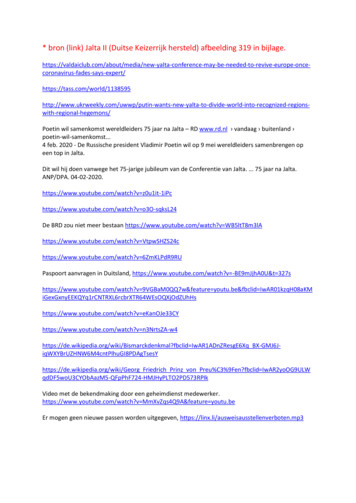
Clearance of the Fresnel Zone andearth curvatureThis table shows the minimum height above flat ground required to clear60% of the first Fresnel zone for various link distances at 2.4 GHz.Notice that earth curvature plays a small role at short distances, butbecomes more important as the distance increases.Distance(km)1st zone(m)60%(m)Earth curvature(m)Requiredheight 5.823030.318.1813.332.520Wednesday, March 5, 14Comment on the values for one or two cases. This table is computed for a frequency of 2.4 GHz.Note that the indicated values refer to the midpoint of the trajectory between the transmitter and the receiver. Assuming flatground, the indicated value corresponds to the height of the towers needed for this link.A good figure to remember is that at 30 km distance over flat land one would need towers about 30 m tall in order to clear theearth curvature and 60 % of the first Fresnel Zone.
Fresnel Zone‣ Considering the importance of the Fresn
Link budget ‣ The performance of any communication link depends on the quality of the equipment being used. ‣ Link budget is a way of quantifying the link performance. ‣ The received power in an wireless link is determined by three factors: transmit power, transmitting antenna gain, and receiving antenna gain.