Transcription
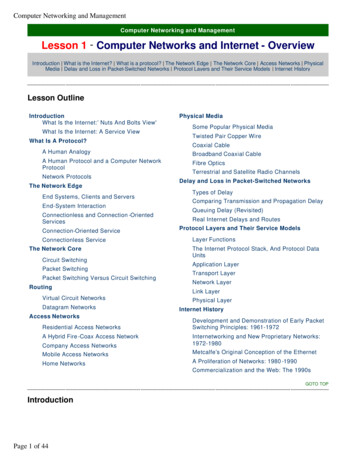
Computer Networking and ManagementComputer Networking and ManagementLesson 5 - The Data Link LayerThe Data Link Layer - Introduction Link Layer and Local Area Networks Link Layer Implementation Error Detection andCorrection Techniques Parity Checks Multiple Access Links and ProtocolsLesson OutlineThe Data Link Layer - IntroductionLink Layer and Local Area NetworksReliable DeliveryError Detection and Correction TechniquesError Detection and Correction ScenarioParity ChecksFlow ControlOne-Bit Even ParityError DetectionInternet Checksum TechniqueError CorrectionCyclic Redundancy Check (CRC)Link Layer ImplementationMultiple Access Links and ProtocolsGOTO TOPThe Data Link Layer - IntroductionGoals:Understand principles behinddata link layer services:lllerror detection,correctionsharing a broadcastchannel: multipleaccesslink layer addressingreliable data transfer,flow controlInstantiation andimplementation of variouslink layer technologiesSome Terminology:Hosts and routers are nodes (bridges and switches too)Communication channels that connect adjacent nodes along communication path are linkslwired linksPage 1 of 9
Computer Networking and Managementlwireless linkslLANs2-PDU is a frame, encapsulates datagramThe data-link layer has responsibility of transferring datagramfrom one node to adjacent node over a linkGOTO TOPLink Layer and Local Area NetworksIn this lesson we examine the data link layer - its services, the principles underlying its operation, and a numberof important data link layer protocols. We learn that the basic service of the data link layer is to move anetwork-layer datagram from one node (host or router) to an adjacent node.We investigate the different services a link layer protocol can provide in addition to this basic service, includinglink access services, delivery services, flow control services and transmission services. These differences aredue in part to a wide variety of link types over which data link protocols must operate.We examine error detection and correction, services that are often present in link-layer protocols. Weinvestigate multiple access protocols, commonly used in LANs (local area networks).Link Layer: Setting the ContextAlmost all link -layer protocols encapsulate each network -layer datagram within alink- layer frame before transmission onto the link. A frame consists of a data field,in which the network -layer datagram is inserted, and a number of header fields. (Aframe may also include trailer fields; however, we will refer to both header andtrailer fields as header fields.)A data-link protocol specifies the structure of the frame, as well as a channelaccess protocol that specifies the rules by which a frame is transmitted onto thelink. For point-to- point links that have a single sender on one end of the link and asingle receiver at the other end of the link, the link-access protocol is simple (ornon-existent) -the sender can send a frame whenever the link is idle. The moreinteresting case is when multiple nodes share a single broadcast link -the so-calledmultiple access problem.Transportation AnalogyTrip from Princeton to LausanneLimo: Princeton to JFKPlane: JFK to GenevaTrain: Geneva to LausanneTourist datagramTransport segment communication linkTransportation mode link layer protocolTravel agent routing algorithmPage 2 of 9Things to Remember:Datagram transferred bydifferent link protocols overdifferent links:e.g., Ethernet on first link,frame relay on intermediatelinks, 802.11 on last linkEach link protocol providesdifferent servicese.g., may or may not providereliable data transfer overlink
Computer Networking and ManagementHere, the channel access protocol serves to coordinate the frame transmissions of the many nodes; Frameheaders also often include fields for a node's so-called physical address, which is completely distinct from thenode's network layer (for example, IP) address.GOTO TOPLink Layer ServicesFraming, Link Accesslencapsulate datagram into frame, adding header, trailerchannel access if shared mediuml‘physical addresses’ used in frame headers to identifysource, destldifferent from IP address!Reliable DeliveryWhen a link-layer protocol provides reliable -delivery service, it guarantees to moveeach network-layer datagram across the link without error. Recall that certaintransport-layer protocols (such as TCP) also provide a reliable -delivery service.Similar to a transport- layer reliable -delivery service, a link -layer reliable -deliveryservice is achieved with acknowledgments and retransmissions.Things to Remember:llseldom used on lowbit error link (fiber,some twisted pair)wireless links: higherror ratesA link-layer reliable -delivery service is often used for links that are prone to high error rates, such as a wirelesslink. The goal is to correct an error locally, on the link where the error occurs, rather than forcing an end-to-endretransmission of the data by a transport - layer or application -layer protocol. However, link -layer reliabledelivery can be considered an unnecessary overhead for low bit-error links, including fibre, coax, and manytwisted -pair copper links. For this reason, many of the most popular link -layer protocols do not provide areliable-delivery service.Discussion Question: Why do we need both link-level and end-end reliability?Flow ControlThe nodes on each side of a link have a limited amount of frame buffering capacity. This is a potential problem,as a receiving node may receive frames at a rate faster than it can process the frames over some time interval.Without flow control, the receiver's buffer can overflow and frames can get lost. Similar to the transport layer, alink-layer protocol can provide flow control in order to prevent the sending node on one side of a link fromoverwhelming the receiving node on the other side of the link.Error DetectionA node's receiver can incorrectly decide that a bit in a frame is zero when it was transmitted as a one, and viceversa. Such bit errors are introduced by signal attenuation and electromagnetic noise. Because there is noneed to forward a datagram that has an error, many link -layer protocols provide a mechanism to detect thepresence of one or more errors. This is done by having the transmitting node set error-detection bits in theframe, and having the receiving node perform an error check. Error detection is a very common service amonglink-layer protocols.Page 3 of 9
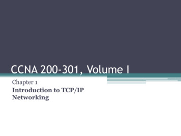
Computer Networking and ManagementError CorrectionError correction is similar to error detection, except that a receiver cannot only detect whether errors have beenintroduced in the frame but can also determine exactly where in the frame the errors have occurred (and hencecorrect these errors).Link Layer ImplementationFor a given communication link, the link-layer protocol is, for the most part,Things to Remember:implemented in an adapter. An adapter is a board (or a PCMCIA card) that typicallycontains RAM, DSP chips, a host bus interface, and a link interface. Adapters areImplemented in 'adapter'also commonly known as network interface cards or NICs.The network layer in the transmitting node (that is, a host or router) passes anetwork-layer datagram to the adapter that handles the sending side of thecommunication link. The adapter encapsulates the datagram in a frame and thentransmits the frame into the communication link. At the other side, the receivingadapter receives the entire frame, extracts the network -layer datagram, and passesit to the network layer.If the link-layer protocol provides:le.g., PCMCIA card,Ethernet Cardltypically includes:RAM, DSP chips,host bus interfaceand link interfacelerror detection, then it is the sending adapter that sets the error detection bits and it is the receivingadapter that performs error checking;lreliable delivery, then the mechanisms for reliable delivery (for example, sequence numbers, timers, andacknowledgments) are entirely implemented in the adapters;lrandom access, then the random access protocol is entirely implemented in the adapters.Error Detection and Correction TechniquesError Detection and Correction ScenarioPage 4 of 9
Computer Networking and ManagementEDC Error Detection and Correction bits (redundancy)D Data protected by error checking, may include header fieldsThe receiver's challenge is to determine whether or not D' is the same as theoriginal D, given that it has only received D' and EDC'.Error-detection and correction techniques allow the receiver to sometimes, but notalways, detect that bit errors have occurred. Even with the use of error-detectionbits there will still be a possibility that undetected bit errors will occur, that is, thatthe receiver will be unaware that the received information contains bit errors.As a consequence, the receiver might deliver a corrupted datagram to the networklayer, or be unaware that the contents of some other field in the frame's headerhave been corrupted. We thus want to choose an error -detection scheme so thatthe probability of such occurrences is small.Things to Remember:lError detection isnot 100% reliable!lProtocol may misssome errors, butrarelylLarger EDC fieldyields betterdetection andcorrectionGenerally, more sophisticated error-detection and correction techniques (that is, those that have a smallerprobability of allowing undetected bit errors) incur a larger overhead - more computation is needed to computeand transmit a larger number of error-detection and correction bits.Note: Error detection and correction services are also often offered at the transport layer as well.Parity ChecksSingle Bit Parity:Detects single bit errorsTwo Dimensional Bit Parity:Detects and corrects single bit errorsPage 5 of 9
Computer Networking and ManagementPerhaps the simplest form of error detection is the use of a single parity bit. Suppose that the information to besent, D has d bits. In an even parity scheme, the sender simply includes one additional bit and chooses itsvalue such that the total number of 1 s in the d 1 bits (the original information plus a parity bit) is even. Forodd parity schemes, the parity bit value is chosen such that there are an odd number of 1s.One-Bit Even ParityReceiver operation is also simple with a single parity bit. The receiver need only count the number of 1s in thereceived d 1 bits. If an odd number of 1-valued bits are found with an even parity scheme, the receiver knowsthat at least one bit error has occurred. More precisely, it knows that some odd number of bit errors haveoccurred.However, measurements have shown that rather than occurring independently, errors are often clusteredtogether in 'bursts'. Under burst error conditions, the probability of undetected errors in a frame protected bysingle -bit-parity can approach 50 percent. Clearly, a more robust error-detection scheme is needed.Internet Checksum TechniqueGoal: detect “errors ” (e.g., flipped bits) in transmitted segment (note: used at transport layer only)In checksumming techniques, the d bits of data are treated as a sequence of k -bit integers. One simplechecksumming method is to simply sum these k-bit integers and use the resulting sum as the error detectionbits. The so-called Internet checksum is based on this approach -bytes of data are treated as 16-bit integersand their ones -complement sum forms the Internet checksum.The receiver calculates the checksum over the received data and checks whether it matches the checksumcarried in the received packet. RFC 1071 discusses the Internet checksum algorithm and its implementation indetail. In the TCP/IP protocols, the Internet checksum is computed over all fields (header and data fieldsincluded). In other protocols, for example, XTP, one checksum is computed over the header, with anotherchecksum computed over the entire packet.Sender:Page 6 of 9Receiver:lTreat segment contents as sequenceof 16-bit integerslCompute checksum of receivedsegmentlChecksum: addition (1’s complementsum) of segment contentslCheck if computed checksum equalschecksum field value:
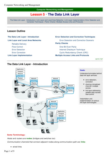
Computer Networking and ManagementlSender puts checksum value intoUDP checksum field¡NO - error detected¡YES - no error detected. Butmaybe errors nonetheless?More later .Cyclic Redundancy Check (CRC)An error -detection technique used widely in today's computer networks is based on cyclic redundancy check(CRC) codes. CRC codes are also known as polynomial codes, since it is possible to view the bit string to besent as a polynomial whose coefficients are the 0 and 1 values in the bit string, with operations on the bit stringinterpreted as polynomial arithmetic.CRC codes operate as follows. Consider the d-bit piece of data, D, that the sending node wants to send to thereceiving node. The sender and receiver must first agree on an r 1 bit pattern, known as a generator, that wewill denote as G. We will require that the most significant (leftmost) bit of G be a 1. The key idea behind CRCcodes is shown in the above diagram. For a given piece of data, D, the sender will choose r additional bits, R,and append them to D such that the resulting d r bit pattern (interpreted as a binary number) is exactlydivisible by G using modulo 2 arithmetic. The process of error checking with CRCs is thus simple: The receiverdivides the d r received bits by G. If the remainder is non-zero, the receiver knows that an error has occurred;otherwise the data is accepted as being correct.Want :D.2 r XOR R nGequivalently:D.2 r nG XOR Requivalently:if we divide D.2 r by G, wantremainder RR remainder [D.2 r / G]Things to Remember:View data bits, D, as a binarynumberChoose r 1 bit pattern(generator), GGoal: choose r CRC bits, R,such thatl D,R exactlydivisible by G(modulo 2)lreceiver knows G,divides D,R by G.If non-zeroremainder: errordetected!lcan detect all bursterrors less than r 1bitsWidely used in practice(ATM, HDCL)Multiple Access links and ProtocolsPage 7 of 9
Computer Networking and ManagementThere are two types of network links -point-to-point links, and broadcast links. Apoint- to -point link consists of a single sender on one end of the link, and a singlereceiver at the other end of the link. Many link -layer protocols have been designedfor point -to -point links;PPP (the point-to-point protocol) and HDLC are two suchprotocols.The second type of link, a broadcast link, can have multiple sending and receivingnodes all connected to the same, single, shared broadcast channel. The termbroadcast is used here because when anyone node transmits a frame, the channelbroadcasts the frame and each of the other nodes receives a copy.Ethernet is probably the most widely deployed broadcast link technology. In thissection we will take a step back from specific link -layer protocols and first examinea problem of central importance to the data-link layer: how to coordinate the accessof multiple sending and receiving nodes to a shared broadcast channel- the socalled multiple access problem.Broadcast channels are often used in local areanetworks (LANs), networks that are geographically concentrated in a single building(or on a corporate or university campus). Thus, we will also look at how multipleaccess channels are used in LANs.Computer networks similarly have protocols -so-called multiple access protocols -twhich nodes regulate their transmission onto the shared broadcast channel. Multipaccess protocols are needed in a wide variety of network settings, including bothwire and wireless local area networks, and satellite networks. In practice, hundredsor eve thousands of nodes can directly communicate over a broadcast channel.Multiple Access ProtocollDistributed algorithm that determines how nodes share channel, i.e.,determine when node can transmitlCommunication about channel sharing must use channel itself!lWhat to look for in multiple access protocols:Page 8 of 9¡synchronous or asynchronous¡information needed about other stationsThings to Remember:Three types of “links”:Point-to-Point ( single wire,e.g. PPP, SLIP)Broadcast (shared wire ormedium;e.g. Ehternet,Wavelan, etc.Switched (e.g. switchedethernet, ATM, etc)Things to Remember:single shared broadcastchanneltwo or more simultaneoustransmissions by nodes:interferencelonly one node cansend successfully ata time
Computer Networking and Management¡robustness ( e.g., to channel errors)¡ performanceMAC protocols: a taxonomyThree broad classes:lllChannel Partitioning¡divide channel into smaller “pieces” (time slots, frequency, code)¡allocate piece to node for exclusive useRandom Access¡channel not divided, allow collisions¡“recover” from collisions“Taking turns”¡tightly coordinate shared access to avoid collisionsWe are all familiar with the notion of broadcasting, as television has been using it since its invention. Buttraditional television is a one-way broadcast (that is, one fixed node transmitting to many receiving nodes),while nodes on a computer network broadcast channel can both send and receive. Perhaps a more apt humananalogy for a broadcast channel is a cocktail party, where many people gather together in a large room (the aproviding the broadcast medium) to talk and listen. A second good analogy is somethin many readers will befamiliar with -a classroom, where teacher(s) and student(s) similarly share the same, single, broadcastmedium. A central problem in both scenarios is that ( determining who gets to talk (that is, transmit into thechannel), and when.As humans, we have evolved an elaborate set of protocols for sharing the broadcast channel:"Give everyone a chance to speak.""Don't speak until you are spoken to.""Don't monopolize the conversation.""Raise your hand if you have a question.""Don't interrupt when someone is speaking.""Don't fall asleep when someone else is talking."Read Chapter 5 of Computer Networking: A Top Down Approach Featuring the Internet, 2nd edition.James Kurose, Keith Ross Addison-Wesley, July 2002.Recommended LinksCharles Spurgeon's Ethernet Web Site http://www.ethermanage.com/ethernetThis site provides extensive information about Ethernet (IEEE 802.3) LAN technology. This includes the original 10 Mbps system, 100 MbpsFast Ethernet (802.3u), 1000 Mbps Gigabit Ethernet (802.3z/802.3ab), and 10 Gigabit Ethernet (802.3ae).Godred Fairhurst's Pages on LANs ages/enet.htmlGodred Fairhurst of the University of Aberdeen maintains a comprehensive set of Web pages on Ethernet, CSMA/CD, bridges, ARP andmany other networking topics.802.11 Planet.com http://www.80211-planet.com802. 11 Planet.com is a Web site devoted to products based on the 802.11 wireless networking protocol. With daily news, features, reviews,and tutorials, this site covers all areas of the rapidly changing 802.11 universe.Working Group for Wireless LAN Standards http://grouper.ieee.org/groups/802/11This is the Web page for the working group that creates the wireless LAN standards, including the standards for IEEE 802.11Bluetooth Sites http://www.bluetooth.com, http://www.bluetooth.orgVisit these sites to learn about what's currently happening in the Bluetooth arena.Tutorials by Nitin Vaidya http://www.crhc.uiuc.edu/ nhv/presentations.htmlThis page provides access to several nice tutorials on wireless LANs and ad hoc networking.Page 9 of 9
The data-link layer has responsibility of transferring datagram from one node to adjacent node over a link GOTO TOP Link Layer and Local Area Networks In this lesson we examine the data link layer - its services, the principles underlying its operation, and a number of important data link layer protocols.