Transcription
IAP-270 Series Outdoor Access PointInstallation GuideThe Aruba IAP-274 and IAP-275 are environmentally hardened, outdoor rated, dual-radio IEEE 802.11acwireless access points. These access points use MIMO (Multiple-in, Multiple-out) technology and otherhigh-throughput mode techniques to deliver high-performance, 802.11ac 2.4 GHz and 5 GHz functionalitywhile simultaneously supporting existing 802.11a/b/g/n wireless services.IAP-270 Series Operations Wireless transceiver Wireless access point (IEEE 802.11 a/b/g/n/ac) Wireless air monitor (IEEE 802.11 a/b/g/n/ac) Protocol-independent networking functionality Compatibility with IEEE 802.3at PoEThe IAP-270 Series requires Aruba Instant 4.1 or later.Guide Overview "IAP-270 Series Hardware Overview" on page 3 provides a detailed hardware overview of the IAP-274and IAP-275. "Before You Begin" on page 7 provides key questions to ask and items to consider when deploying anoutdoor wireless network. "Installing the AP" on page 8 describes the multi-step process for a successful installation anddeployment of the IAP-274 and IAP-275. "Safety and Regulatory Compliance" on page 14 provides an overview of safety and regulatorycompliance information.Package Contents IAP-274 or IAP-275 Access Point Cable Glands x2 Copper Lug x1 M4x6 Screw x1 USB Console Cable Aruba Instant Quick Start Guide Installation Guide (this document)The weatherproof caps for Ethernet, Console, and power interfaces are connected to the AP, not loose in thepackage.0511605-04 December 20171
Mounting kits for use with the IAP-270 Series access points are sold separately. Contact your Aruba salesrepresentative for details.Inform your supplier if there are any incorrect, missing, or damaged parts. If possible, retain the carton, includingthe original packing materials. Use these materials to repack and return the unit to the supplier if needed.2IAP-270 Series Outdoor Access Point Installation Guide
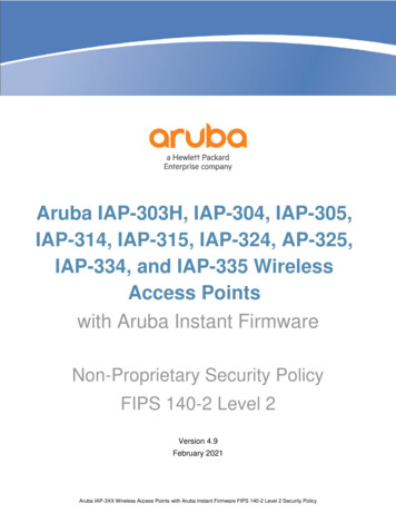
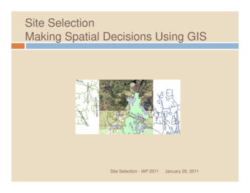
IAP-270 Series Hardware OverviewFigure 1 IAP-274 Front View (Aesthetic Cover Removed)System LEDThe antenna connectors of IAP-274 are covered by an aesthetic cover in the package. The aesthetic cover can beremoved when necessary.Figure 2 IAP-275 Front ViewSystem LEDLEDThe IAP-270 Series is equipped with one LED that indicates the system status of the AP.IAP-270 Series Outdoor Access Point Installation Guide3
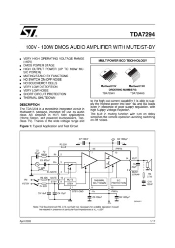
Table 1 IAP-270 Series LED Meanings during Boot UpLEDColor/StateMeaningSystem LEDOffNo power to APRedInitial power-upGreen - FlashingAP bootingGreen - SteadyAP ready and 1000Mbps Ethernet link established. The LED turnsoff after 1200 secondsGreen - Yellow, 6 secondsperiodAP ready and 10/100Mbps Ethernet link established. The LEDturns off after 1200 secondsTable 2 IAP-270 Series LED Meanings during OperationLEDColor/StateMeaningSystem LEDSolid RedGeneral faultOne blink off every 3secondsRadio 0 fault (5 GHz)Two quick blink off 0.5seconds apart cycled every3 secondsRadio 1 fault (2.4GHz)Figure 3 IAP-274 Rear ViewGrounding PointUSB Console Port and Reset buttonAC Power InterfaceLAN PortWAN Port4IAP-270 Series Outdoor Access Point Installation Guide
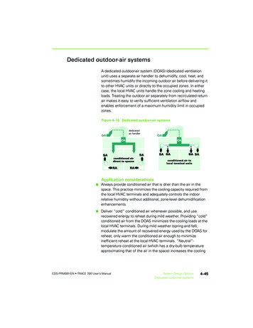
Figure 4 IAP-275 Rear ViewGrounding PointUSB Console Port and Reset buttonAC Power InterfaceLAN PortWAN PortUSB Console PortThe USB Micro-B console port allows you to connect the AP to a terminal or a laptop for direct localmanagement. Use the included USB console cable to connect the AP. You can download the necessarydriver for USB-UART adapter from support.arubanetworks.com under the Tools & Resources tab.Use the following setting to access the terminal:Table 3 Console SettingsBaud RateData BitsParityStop BitsFlow Control96008None1NoneEthernet PortsIAP-270 Series is equipped with two10/100/1000Base-T (RJ-45) Gigabit Ethernet ports (WAN and LAN port)for wired network connectivity. The WAN port supports 802.3at Power over Ethernet (PoE), accepting 48VDC (nominal) as a standard defined Powered Device (PD) from a Power Sourcing Equipment (PSE) suchas a PoE midspan injector.These ports have RJ-45 female connectors with the pin-outs shown in Figure 5.Figure 5 Gigabit Ethernet Port Pin-Out1000Base-T GigabitEthernet PortRJ-45 FemalePin-Out12345678Signal NameFunctionBI DA BI DABI DB BI DC BI DCBI DBBI DD BI DD-Bi-directional pair A, POE NegativeBi-directional pair -A, POE NegativeBi-directional pair B, POE PositiveBi-directional pair C, POE PositiveBi-directional pair -C, POE PositiveBi-directional pair -B, POE PositiveBi-directional pair D, POE NegativeBi-directional pair -D, POE NegativeReset ButtonThe reset button can be used to return the AP to factory default settings. To reset the AP:IAP-270 Series Outdoor Access Point Installation Guide5
1. Power off the AP.2. Press and hold the reset button using a small, narrow object, such as a paperclip.3. Power-on the AP without releasing the reset button. The system LED will flash within 5 seconds.4. Release the reset button.The system LED will flash again within 15 seconds indicating that the reset is completed. The AP will nowcontinue to boot with the factory default settings.AC Power InterfaceThe IAP-270 Series is capable of AC power in the range of 100 - 240 VAC. The power cord or powerconnector kit is sold separately.Grounding PointAlways remember to protect the AP by installing grounding lines. The ground connection must be completebefore connecting power to the AP enclosure.Figure 6 IAP-274 and IAP-275 Top ViewMounting HolderSolar ShieldAt the top of the IAP-270 Series, the solar shield with the mounting holder is fixed onto the AP beforeshipping from the factory.Figure 7 IAP-274 Bottom ViewWith Aesthetic Cover6Aesthetic Cover RemovedIAP-270 Series Outdoor Access Point Installation Guide
Figure 8 IAP-275 Bottom ViewAir VentExternal Antenna ConnectorsThe IAP-274 is equipped with six N-type female connectors.for external antenna. The connectors arelabeled 2G0, 2G1, 2G2, 5G0, 5G1 and 5G2, and correspond to 2.4/5Ghz radio chains 0,1, and 2.Please install the external antennas according to the manufacturer’s instruction and connect the antennas to the Ntype female antenna connectors on the IAP-274 access point.External antennas for this device must be installed by an Aruba Certified Mobility Professional (ACMP) or otherAruba-certified technician, using manufacturer-approved antennas only.The Equivalent Isotropically Radiated Power (EIRP) levels for all external antenna devices must not exceed theregulatory limit set by the host country/domain.Installers are required to record the antenna gain for this device in the system management software.!Les antennes externes pour cet appareil doivent être installées par un professionnel de la mobilité certifié Aruba(ACMP) ou un autre technicien certifié Aruba, en utilisant uniquement des antennes approuvées par le fabricant.Les niveaux équivalents de puissance à rayonnement isotrope (EIRP) pour tous les périphériques d'antenneexterne ne doivent pas dépasser la limite réglementaire définie par le pays hôte / domaine.Les installateurs doivent enregistrer le gain d'antenne pour cet appareil dans le logiciel de gestion du système.Air VentThe bottom of the IAP-270 Series has an air vent to balance the pressure and humidity inside and outsidethe AP. It also allows air exchange between the AP and the environment in a controlled way that doesn’tallow water to get into the AP.Before You Begin!FCC Statement: Improper termination of access points installed in the United States (non-US model RegulatoryDomain model/s) will be in violation of the FCC grant of equipment authorization. Any such willful or intentionalviolation may result in a requirement by the FCC for immediate termination of operation and may be subject toforfeiture (47 CFR 1.80).IAP-270 Series Outdoor Access Point Installation Guide7
EU Statement:Lower power radio LAN product operating in 2.4 GHz and 5 GHz bands. Please refer to the Aruba Instant UserGuide for details on restrictions.!Produit réseau local radio basse puissance operant dans la bande fréquence 2.4 GHz et 5 GHz. Merci de vousreferrer au Aruba Instant User Guide pour les details des restrictions.Low Power FunkLAN Produkt, das im 2.4 GHz und im 5 GHz Band arbeitet. Weitere Informationen bezlüglichEinschränkungen finden Sie im Aruba Instant User Guide.Apparati Radio LAN a bassa Potenza, operanti a 2.4 GHz e 5 GHz. Fare riferimento alla Aruba Instant User Guideper avere informazioni detagliate sulle restrizioni.Aruba Networks, Inc. in compliance with governmental requirements, has designed the IAP-270 Series such thatonly authorized network administrators can change configuration settings. For more information about APconfiguration, refer to the Aruba Instant Quick Start Guide and Aruba Instant User Guide.!Access points are radio transmission devices and as such are subject to governmental regulation. Networkadministrators responsible for the configuration and operation of access points must comply with local broadcastregulations. Specifically, access points must use channel assignments appropriate to the location in which theaccess point will be used.Identifying Specific Installation LocationsYou can mount the IAP-270 Series access point on a wall or pole. Use the AP placement map generated byAruba’s RF Plan software application to determine the proper installation location(s). Each location shouldbe as close as possible to the center of the intended coverage area and should be free from obstructions orobvious sources of interference. These RF absorbers/reflectors/interference sources will impact RFpropagation and should have been accounted for during the planning phase and adjusted for in RF plan.Identifying Known RF Absorbers/Reflectors/Interference SourcesIdentifying known RF absorbers, reflectors, and interference sources while in the field during theinstallation phase is critical. Make sure that these sources are taken into consideration when you attach anAP to its fixed location. Examples of sources that degrade RF performance include: Cement and brickObjects that contain waterMetalMicrowave ovens Wireless phones and headsets Installing the APService to all Aruba products should be performed by trained service personnel only.8IAP-270 Series Outdoor Access Point Installation Guide
Using the Mounting KitsThe IAP-270 Series can be installed on a wall or attached to a pole by using mounting kits:Table 4 Applicable Mounting Kits for IAP-270 SeriesPart NumberDescriptionAP-270-MNT-V1Long mounting kit for wall and vertical pole mounting, 300 mm from vertical mountingasset.AP-270-MNT-V2Short mounting kit for wall and vertical pole mounting, 75 mm from vertical mountingasset.AP-270-MNT-H1Mounting kit for hanging from inclined or horizontal structure.The IAP-270 Series access point does not ship with any mounting kits. These mounting kits are available asaccessories.and must be ordered separately.For installation instructions on AP-270-MNT-V1, AP-270-MNT-V2 and AP-270-MNT-H1, please refer to the AP270-MNT-V1 Installation Guide, AP-270-MNT-V2 Installation Guide and AP-270-MNT-H1 Installation Guiderespectively.Grounding the APThe grounding must be completed before powering up the AP. The grounding wire should be #8 AWG.1. Peel the cover of one end of the grounding wire and place the bare grounding wire into the includedcopper lug, and press firmly with the crimping pliers.2. Fasten the copper lug to the grounding hole on the AP with the included M4 x6 screw as shown in Figure9.Figure 9 Grounding the APConnecting the Ethernet CableTo connect the Ethernet cable to the AP, perform the following steps using the cable glands that ships withyour AP.Failure to use the included Ethernet cable glands can lead to connectivity and POE issues.IAP-270 Series Outdoor Access Point Installation Guide9
The cable is not included and must be purchased separately. Purchase a suitable UV-resistant, outdoor rated, CAT5E or better RJ45 cable for use with the AP.Figure 10 Installing a Cable GlandSealsSealing NutClamping RingCAT 5E or Better Cable1. Slide the sealing nut over the cable (without the RJ45 connector attached to the end).2. Slide the clamping ring over the cable.3. Using a crimping tool, attach the shielded RJ45 connector to the end of the cable.4. Remove the weatherproof cap on the Ethernet port.5. Insert the RJ45 connector to the Ethernet port.6. Screw the clamping ring onto the Ethernet port.7. Screw the sealing nut onto the clamping ring.The seals inside the clamping ring by factory default is applicable for cables with 5-8.5 mm diameter. In the cablegland kit, another seals is provided for use with the cables with 7-10 mm diameter.Connecting the Power Cable!Installation and service of Aruba products should be performed by Professional Installers in a manner that isconsistent with the electrical code in force in the jurisdiction of deployment. In many countries this will require alicensed electrician to perform this operation. In Japan, this is a Certified Electrician by Ministry of Economy, Trade,and Industry.The IAP-270 Series does not ship with any power cables. These are available as accessories and should be orderedseparately.The IAP-270 Series product offering offers two ways to connect the unit to AC power. Two power cordvariants are offered and a connector kit that allows the customer to assemble their own cable if thestandard offering does not meet deployment needs.The applicable SKUs for these options are:Table 5 SKUs for Powering Options10Part NumberDescriptionPC-OD-AC-P-NAWeatherproof AC power cable(5m), North America versionPC-OD-AC-P-INTWeatherproof AC power cable(5m), International (EU) versionIAP-270 Series Outdoor Access Point Installation Guide
Table 5 SKUs for Powering OptionsPart NumberDescriptionCKIT-OD-AC-PWeatherproof connector kit for AC power interfaceThe difference between the NA and INTL part variants is the color coding of the conductors.! The North American cable uses Black (Hot), White (Neutral), and Green (Ground). The INTL part follows the international schema of Brown (Hot), Blue (Neutral) and Yellow/Green(Ground)Please only use included or Aruba specified cables, power cords, AC power supplies and batteries. The power cordshould not be used with other electric equipment than what is specified by ArubaBest Practice for Outdoor Connection to AC MainsIn all circumstances and with any outdoor infrastructure the recommended practice is to connect to ACmains in an order grade weather protected junction box. This needs to be implemented by a qualifiedresource in a manner that is consistent with the electrical code in force in the jurisdiction of deployment. Inmany countries this will require a licensed electrician to perform this operation.In Japan, this would is a Certified Electrician by Ministry of Economy, Trade and Industry.The use of plugs with infrastructure equipment is suitable only for temporary installs where nuisancetripping of GFI plugs is considered tolerable. Should it be desired to attach a plug to the cable assembliesthen the installer is expected to follow all directions provided with the plug end in a fashion consistent withlocal electrical code.Use of the CKIT-OD-AC-PAssembly instructions for this part are shipped with the part. All instructions must be followed to ensureproper assembly of the connector onto the cable.The required specifications for third party cable used with the CKIT solution are as follows: AC power cable specifications (when using AC connector kit and custom cable): minimum voltage/current rating 250V/1A, diameter 6-12mm, rated for outdoor use and UV exposureAC Power Cable Connector PIN OUTFigure 11 AC power cable connectorNeutralHotGroundConnecting the Power Cable to the IAP-2751. Remove the weatherproof cap on the power interface.IAP-270 Series Outdoor Access Point Installation Guide11
2. Insert the power cable connector into the power interface and hand-fasten the locknut.Verifying Post-Installation ConnectivityThe integrated LEDs on the AP can be used to verify that the AP is receiving power and initializingsuccessfully (see Table 1 and Table 2). Refer to the Aruba Instant Quick Start Guide for further details onverifying post-installation network connectivity.12IAP-270 Series Outdoor Access Point Installation Guide
Product SpecificationsMechanical: Device Dimensions (HxWxD) IAP-274 (without aesthetic cover): 5.5 inches x 9 inches x 9.4 inches (14cm x 23cm x 24cm) IAP-274 (with aesthetic cover): 7.5 inches x 9 inches x 9.4 inches (19cm x 23cm x 24cm) IAP-275: 10.6 inches x 9 inches x 9.4 inches (27cm x 23cm x 24cm)Weight IAP-274(without aesthetic cover): 5.3 lbs/2.4 kg IAP-274 (with aesthetic cover): 6lbs/2.7kg IAP-275: 5.3 lbs/2.4 kgElectrical Ethernet 2 x 10/100/1000Base-T auto-sensing Ethernet RJ-45 Interfaces MDI/MDX Power over Ethernet (IEEE 802.3at compliant), 48VDC/0.6APower 100-240 VAC 50/60 Hz from external AC power source POE support on WAN port: 802.3at-compliant POE sourcing devicesEnvironmental Operating Temperature: -40ºC to 65ºC (-40ºF to 150ºF) Humidity: 5% to 95% non-condensingStorage Temperature: -40ºC to 70ºC (-40ºF to 158ºF)For additional specifications on this product, please refer to the data sheet. The data sheet can be found atwww.arubanetworks.com.IAP-270 Series Outdoor Access Point Installation Guide13
Safety and Regulatory ComplianceAruba Networks provides a multi-language document that contains country-specific restrictions andadditional safety and regulatory information for all Aruba access points. This document can be viewed ordownloaded from the following location: www.arubanetworks.com/safety addendumRegulatory Model NameThe following regulatory model names apply to the IAP-270 Series: IAP-274: APEX0101IAP-275: APEX0100FCCThis device is electronically labeled. To view the FCC ID:1. Log into the controller WebUI2. Navigate to Maintenance Controller About.!Aruba access points must be installed by a professional installer. The professional installer is responsible forensuring that grounding is available and it meets applicable local and national electrical codes.!RF Radiation Exposure Statement: This equipment complies with FCC RF radiation exposure limits. Thisequipment should be installed and operated with a minimum distance of 13.78 inches (35 cm) between the radiatorand your body for 2.4 GHz and 5 GHz operations. This transmitter must not be co-located or operating inconjunction with any other antenna or transmitter. When operated in the 5.15 to 5.25 GHz frequency range, thisdevice is restricted to indoor use to reduce the potential for harmful interference with co-channel Mobile SatelliteSystems.FCC Class B Part 15This device complies with Part 15 of the Federal Communications Commission (FCC) Rules. Operation issubject to the following two conditions:! This device may not cause harmful interference. This device must accept any interference received, including interference that may cause undesiredoperation.Changes or modifications to this unit not expressly approved by the party responsible for compliance could voidthe user’s authority to operate this equipment.This equipment has been tested and found to comply with the limits for a Class B digital device, pursuant toPart 15 of the FCC Rules. This equipment generates, uses and can radiate radio frequency energy and, if notinstalled and used in accordance with the manufacturer’s instructions, may cause interference harmful toradio communications.If this equipment does cause interference, which can be determined by turning the equipment off and on,the user is encouraged to try to correct the interference by one or more of the following measures:14 Reorient or relocate the receiving antenna. Increase the separation between the equipment and receiver. Connect the equipment to an outlet on a circuit different from that to which the receiver is connected. Consult the dealer or an experienced radio or TV technician for help.IAP-270 Series Outdoor Access Point Installation Guide
EU Regulatory ConformanceAruba Networks, Inc., hereby declares that the APEX0101 and APEX0100 device models are incompliance with the essential requirements and other relevant provisions of Directive 1999/5/EC -CE(!).The Declaration of Conformity made under Directive 1999/5/EC is available for viewing atwww.arubanetworks.com.Proper Disposal of Aruba EquipmentFor the most current information about Global Environmental Compliance and Aruba products, see ourwebsite at www.arubanetworks.com.Waste of Electrical and Electronic EquipmentAruba products at end of life are subject to separate collection and treatment in the EUMember States, Norway, and Switzerland and therefore are marked with the symbolshown at the left (crossed-out wheelie bin). The treatment applied at end of life of theseproducts in these countries shall comply with the applicable national laws of countriesimplementing Directive 2002/96EC on Waste of Electrical and Electronic Equipment(WEEE).European Union RoHSAruba products also comply with the EU Restriction of Hazardous SubstancesDirective 2011/65/EC (RoHS). EU RoHS restricts the use of specific hazardousmaterials in the manufacture of electrical and electronic equipment. Specifically,restricted materials under the RoHS Directive are Lead (including Solder used inprinted circuit assemblies), Cadmium, Mercury, Hexavalent Chromium, and Bromine. Some Aruba productsare subject to the exemptions listed in RoHS Directive Annex 7 (Lead in solder used in printed circuitassemblies). Products and packaging will be marked with the “RoHS” label shown at the left indicatingconformance to this Directive.China RoHS10Aruba products also comply with China environmental declaration requirements and arelabeled with the “EFUP 10” label shown at the left.᳝ ᳝ᆇ 䋼ໄᯢHazardous Materials Declaration䚼ӊৡ (Parts) 䏃ᵓ (PCA Boards) ᴎẄ㒘ӊ (Mechanical Sub-Assemblies)ƻ ᳝ ᳝ᆇ 䋼 ܗ (Hazardous Substance)䬝 ݁Ӌ䫀 ⒈㘨㣃 &G&U 3%%䪙 3E Jhƻƻƻƻƻhƻƻƻƻƻ ⒈Ѡ㣃䝮 3%'(㸼 䆹᳝ ᳝ᆇ 䋼 䆹䚼ӊ᠔᳝ഛ䋼ᴤ᭭Ёⱘ 䞣ഛ SJ/T11363-2006 ᷛ ޚ 㾘ᅮⱘ䰤䞣㽕 ҹϟDŽIndicates that the concentration of the hazardous substance in all homogeneous materials in the parts isbelow the relevant threshold of the SJ/T11363-2006 standard.h 㸼 䆹᳝ ᳝ᆇ 䋼㟇ᇥ 䆹䚼ӊⱘᶤϔഛ䋼ᴤ᭭Ёⱘ 䞣䍙ߎ6- 7 ᷛ ޚ 㾘ᅮⱘ䰤䞣㽕 DŽ Indicates that the concentration of the hazardous substance of at least one of all homogeneous materialsin the parts is above the relevant threshold of the SJ/T11363-2006 standard.ᇍ䫔ଂП᮹ⱘ᠔ଂѻક ᴀ㸼ᰒ կᑨ䫒ⱘ ᄤֵᙃѻકৃ㛑ࣙ 䖭ѯ 䋼DŽ This table shows where these substances may be found in the supply chain of electronic informationproducts, as of the date of sale of the enclosed product.ℸᷛᖫЎ䩜ᇍ᠔ ঞѻકⱘ⦃ֱՓ ᳳᷛᖫ ᶤѯ䳊䚼ӊӮ᳝ϔϾϡৠⱘ⦃ֱՓ ᳳ՟བ ऩ ܗ ഫ 䌈 ݊ѻકϞ ℸ⦃ֱՓ ᳳ䰤া䗖 Ѣѻકᰃ ѻક ݠ Ё᠔㾘ᅮⱘᴵӊϟᎹ The Environment- Friendly Use Period (EFUP) for all enclosed products and their parts areper the symbol shown here. The Environment- Friendly Use Period is valid only when theproduct is operated under the conditions defined in the product manual.IAP-270 Series Outdoor Access Point Installation Guide15
Canadian StatementUnder Industry Canada regulations, this radio transmitter may only operate using an antenna of a type andmaximum (or lesser) gain approved for the transmitter by Industry Canada. To reduce potential radiointerference to other users, the antenna type and its gain should be so chosen that the equivalentisotropically radiated power (e.i.r.p.) is not more than that necessary for successful communication.This device complies with Industry Canada licence-exempt RSS standard(s).Operation is subject to the following two conditions: (1) this device may not cause interference, and (2) thisdevice must accept any interference, including interference that may cause undesired operation of thedevice.Canadian CautionThis radio transmitter (identify the device by certification number, or model number if Category II) hasbeen approved by Industry Canada to operate with the antenna types listed below with the maximumpermissible gain and required antenna impedance for each antenna type indicated. Antenna types notincluded in this list, having a gain greater than the maximum gain indicated for that type, are strictlyprohibited for use with this device.Gain of antenna: 14.0dBi max/10dBi max;Type of antenna: directional/ommi;Impedance of antenna: 50ohmLe présent émetteur radio (identifier le dispositif par son numéro de certification ou son numéro de modèles'il fait partie du matériel de catégorie I) a été approuvé par Industrie Canada pour fonctionner avec lestypes d'antenne énumérés ci-dessous et ayant un gain admissible maximal et l'impédance requise pourchaque type d'antenne. Les types d'antenne non inclus dans cette liste, ou dont le gain est supérieur au gainmaximal indiqué, sont strictement interdits pour l'exploitation de l'émetteur.Gain d'antenne: 14.0dBi maximal/10dBi maximal;Type d'antenne: 50 ohm, directionnel/ommi.16IAP-270 Series Outdoor Access Point Installation Guide
Philippines (IAP-274)Type-Approval No.ESD-1408699CPhilippines (IAP-275)Type-Approval No.ESD-1408698CHong Kong (IAP-274)HK0011400885Hong Kong (IAP-275)HK0011400884UAE (IAP-274)TRAREGISTERED No:ER01290403/14DEALER No:DA0039425/10UAE (IAP-275)TRAREGISTERED No:ER0129040/14DEALER No:DA0039425/10IAP-270 Series Outdoor Access Point Installation Guide17
Singapore (IAP-274 and IAP-275)DB10152518IAP-270 Series Outdoor Access Point Installation Guide
This page is intentionally left blank.IAP-270 Series Outdoor Access Point Installation Guide19
Contacting Aruba NetworksWebsite SupportMain Sitearubanetworks.comSupport Sitesupport.arubanetworks.comAirheads Social Forums and KnowledgeBasecommunity.arubanetworks.comNorth American Telephone1-800-943-4526 (Toll Free)1-408-754-1200International ct-support/Software Licensing Sitelicensing.arubanetworks.com/End of Support of-life-products/end-of-life-policy/Security IncidentResponse Team ulletins/Support Email AddressesAmericas, EMEA, and APACsupport@arubanetworks.comSecurity IncidentResponse Team (SIRT)sirt@arubanetworks.comOpen Source CodeThis product includes code licensed under the GNU General Public License, the GNU Lesser General PublicLicense, and/or certain other open source licenses. A complete machine-readable copy of the source codecorresponding to such code is available upon request. This offer is valid to anyone in receipt of this informationand shall expire three years following the date of the final distribution of this product version by Hewlett PackardEnterprise Company. To obtain such source code, send a check or money order in the amount of US 10.00 to:Hewlett Packard Enterprise CompanyAttn: General Counsel3000 Hanover StreetPalo Alto, CA 94304USAWarrantyThis hardware product is protected by an Aruba warranty. For details, see Aruba Networks standard warrantyterms and conditions. Copyright 2017 Hewlett Packard Enterprise Development LPwww.arubanetworks.com3333 Scott BlvdSanta Clara, CA 95054Phone: 1 408 227 4500Fax: 1 408 752 062620IAP-270 Series Outdoor Access Point Installation Guide
"IAP-270 Series Hardware Overview" on page 3 provides a detailed hardware overview of the IAP-274 . External antennas for this device must be installed by an Aruba Certified Mobility Professional (ACMP) or other Aruba-certified technician, using manufacturer-approved antennas only. . asset. AP-270-MNT-V2 Short mounting kit for wall and .