Transcription
Chapter 5Enterprise Data Center Design1
Enterprise Data Center The data center is home to the computational power,storage, and applications necessary to support anenterprise business. be carefully considered performance, resiliency, andscalability.The layered approach is the basic foundation of thedata center design that seeks to improve scalability,performance, flexibility, resiliency, and maintenance.2
Data Center Architectural Overview3
Enterprise Data Center Virtualization allows optimization of the datacenter provides many services. It allows resources on demand, and optimization ofcomputer and network resources.Virtualization also lowers operating expenses(OPEX) by optimizing power; heating,ventilation, air conditioning (HVAC); and datacenter floor space.4
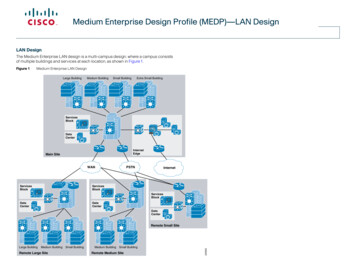
Enterprise Data Center The data center architecture is based on athree-layer approach. The core layer provides a high-speed Layer 3fabric for packet switching. The aggregation layer extends spanning-treeor Layer 3 routing protocols into the accesslayer, depending on which access layermodel is used. The access layer provides physicalconnectivity for the servers.5
Access Layer The access layer supports both Layer 2 and Layer 3topologies. Layer 2 adjacency requirements that fulfill the various serverbroadcast domain or administrative requirements.The server components can consist of single and dualattached one-rack unit (1RU) servers, blade serverswith integral switches. blade servers with pass-through cabling, clustered servers, andmainframes with a mix of oversubscription requirements.6
Aggregation Layer The aggregation layer supports integratedservice modules that provide services such as security, load balancing, content switching, firewall, Secure Sockets Layer (SSL) offload, intrusion detection, network analysis.7
Note Small and medium data centers have a two-tierdesign, with the Layer 3 access layer connectedto the backbone database core (collapsed coreand aggregation layers).Three-tier designs allow for greater scalabilityin the number of access ports, but a two-tierdesign is ideal for small server farms.8
The Benefits for Separation Layer1. Layer 2 domain sizing: When a requirement exists to extend a VLAN fromone switch to another, the domain size isdetermined at the aggregation layer.If the access layer is absent, the Layer 2 domainmust be configured across the core for extension tooccur. Extending Layer 2 through a core causes pathblocking by the spanning tree, which might causeuncontrollable broadcast issues related toextending Layer 2 domains and should beavoided.9
Benefits2.Service module support: 3.The aggregation layer with the access layer and enablesservices to be shared across the entire access layer ofswitches.This lowers the total cost of ownership (TCO) and lowerscomplexity by reducing the number of components to configureand manage.Support for a mix of access layer models: The three-layer approach permits a mix of both Layer 2 andLayer 3 access models with 1RU and modular platforms,permitting a more flexible solution and allowing applicationenvironments to be optimally positioned.10
Benefits4. Support for network interface card (NIC) teaming andhigh-availability clustering: Supporting NIC teaming with switch fault tolerance and highavailability clustering requires Layer 2 adjacency between NICs,resulting in Layer 2 VLAN extension between switches.VLAN extension can also require extending the Layer 2 domainthrough the core, which is not recommended.11
Note The extension of VLANs across the data center coreand other layers is not best practice. Customer requirements such as clustering or virtual machinemobility across multiple data centers may require VLANs to beextended across the data center core.These cases significantly change the data center coredesign and introduce the risk of failures in one area ofthe network affecting the entire network.Therefore, network designers should investigatetechnologies such as Cisco Overlay TransportVirtualization (OTV) to overcome the drawbacks andmitigate the risks of stretching Layer 2 domains acrossa data center core.12
Cisco Overlay Transport Virtualization A critical network design requirement fordeployment of distributed virtualization andcluster technologies is having all servers in thesame Layer 2 VLAN.Meeting this requirement means extendingVLANs over Layer 3 networks, but currentsolutions introduce operational and resiliencychallenges.13
Cisco Overlay Transport Virtualization OTV is a new industry solution, providing customerswith an innovative yet simple means of extending Layer2 networks over Layer 3 networks for both intra– andinter–data center applications without the operationalcomplexities of existing interconnect solutions14
Cisco Overlay Transport Virtualization OTV can be thought of as MAC-address routing, inwhich destinations are MAC addresses, and next hopsare IP addresses.Traffic destined for a particular MAC address isencapsulated in IP and carried through the IP cloud toits MAC-address routing next hop.15
The Services Layer Load balancing and security services can be integratedin the aggregation layer of the data center or designedas a separate layer.16
The Services Layer Load balancing, firewall services, and other networkservices are commonly integrated in the aggregationlayer in the aggregation switches. It allows for a compact design, saving on power, rack space,and cabling.When you run out of ports on the aggregationswitches, you must add a new pair of aggregationswitches, including additional service modules. Using this approach effectively links service scaling andaggregation layer scaling.17
Dedicated Service Appliances Network services can be implemented on external,standalone devices that are commonly referred to asappliances.When choosing between a design that is based onappliances or service chassis, you should consider thefollowing design aspects: Power and rack space: Combining several service modules in asingle Catalyst 6500 series chassis may require less rack spaceand reduce the power requirements compared with usingseveral external appliances.18
Dedicated Service Appliances Performance and throughput: The performance of some of the individual appliances can behigher than the corresponding service module.Fault tolerance: Appliances are connected to only one of the aggregation layerswitches. When that aggregation switch fails, any directly attachedappliances are also lost.A service chassis can be dual-homed to two different aggregationswitches. The loss of an aggregation layer switch does not cause theassociated service chassis to be lost.Required services: Some services are supported on an appliance but not on thecomparable service module. However, there is now a Cisco ASA service module that no longer has this limitation19
Core Layer Design The core layer provides a fabric for high-speed packet switchingbetween multiple aggregation modules.The core layer is not necessarily required but is recommendedwhen multiple aggregation modules are used for scalability.20
Core Layer Design Whether to implement a data center core, consider the following: 10 Gigabit Ethernet port densityAdministrative domains and policies: Separate cores help isolate campus distribution layers and data centeraggregation layers in terms of administration and policies, such as qualityof service (QoS), access lists, troubleshooting, and maintenance.Future growth: The impact of implementing a separate data center core layer at a laterdate might make it worthwhile to implement it during the initialimplementation stage. (系統implement的明確性)The core layer serves as the gateway to the campus core, whereother campus modules connect, including the enterprise edge andWAN modules.Links connecting the data center core are connected at Layer 3(use Layer 3) and use a distributed, low-latency forwardingarchitecture and 10 Gigabit Ethernet interfaces for a high level ofthroughput and performance.21
Layer 3 Characteristics for the DataCenter Core When designing the enterprise data center, consider where in theinfrastructure to place the Layer 2 to Layer 3 boundary22
Layer 3 Characteristics for the DataCenter Core The recommended practice is the core infrastructure to be implemented at Layer 3 the Layer 2 to Layer 3 boundary to be implementedeither within or below the aggregation layermodules.Layer 3 links allow the core to achieve bandwidthscalability and quick convergence, and to avoid pathblocking or the risk of uncontrollable broadcast issuesrelated to extending Layer 2 domains. Layer 2 should be avoided in the core because a Spanning TreeProtocol (STP) loop could cause a full data center outage.23
Layer 3 Characteristics for the DataCenter Core The core layer should run an interior routing protocol such asOpen Shortest Path First (OSPF) or Enhanced Interior GatewayRouting Protocol (EIGRP), and load balance traffic between thecampus core and core aggregation layers using Cisco ExpressForwarding (CEF)-based hashing algorithms.From a campus core perspective, at least two equal-cost routes tothe server subnets permit the core to load balance flows to eachaggregation switch in a particular module. Load balancing is performed using CEF-based load balancing on Layer 3 sourceand destination IP address hashing.An option is to use Layer 3 IP plus Layer 4 port-based CEF load-balancehashing algorithms. This usually improves load distribution because it presents more uniquevalues to the hashing algorithm in the client TCP stack.24
Cisco Express Forwarding CEF is a deterministic algorithm.25
Cisco Express Forwarding CEF determines the longest path match for thedestination address using a hardware lookup.Each specific index is associated with a next-hopadjacencies table. By default, one of the possible adjacencies is selected by ahardware hash where the packet source and destination IPaddress are used.As a configurable alternative, one of the possible adjacenciescan also be selected by a hardware hash using L4 portinformation in addition to the packet source and destination IPaddress.The new MAC address is attached and the packet isforwarded.26
OSPF Routing Protocol DesignRecommendations The OSPF routing protocol design should be tuned forthe data center core layer.Backbone area27
OSPF Routing Protocol DesignRecommendations The OSPF routing protocol suggested configuration is as follows:Use a not-so-stubby area (NSSA) from the core down. It limitslink-state advertisement (LSA) propagation but permits routeredistribution.You can advertise the default route into the aggregation layer andsummarize the routes coming out of the NSSA.Use the auto-cost reference-bandwidth 10000 command toset the bandwidth to a 10 Gigabit Ethernet value and allow OSPFto differentiate the cost on higher-speed links, such as 10 GigabitEthernet trunk links. This is needed because the OSPF default reference bandwidth is 100 Mbps.28
OSPF OSPF relies on several types of Link StateAdvertisements (LSAs) to communicate link stateinformation between neighbors.A brief review of the most applicable LSA types: Type 1 - Represents a routerType 2 - Represents the pseudonode (designated router) for amultiaccess linkType 3 - A network link summary (internal route)Type 4 - Represents an ASBRType 5 - A route external to the OSPF domainType 7 - Used in stub areas in place of a type 5 LSA29
OSPF LSA types 1 and 2 are found in all areas, and are neverflooded outside of an area.Whether the other types of LSAs are advertised withinan area depends on the area type, and there are many:Backbone area (area 0)Standard areaStub areaTotally stubby areaNot-so-stubby area (NSSA)30
OSPF Hierarchy architecture: backbone router: the router of area 0 internal router: the inner routers of samearea ABR(area broder router): each interfaceconnects to different areas, but at least oneinterface connects with area 0. ASBR(autonomous system border router):connect with other as, and imports other as’s(Autonomous System) routing informationinto own OSPF.31
Standard Areas Backbone area is essentially a standard area which has beendesignated as the central point to which all other areas connect, soa discussion of standard area behavior largely applies to thebackbone area as well.Router 2 acts as the area border router (ABR) between a standardarea and the backbone. R3 is redistributing routes from anexternal domain, and is therefore designated as an autonomoussystem boundary router (ASBR).32
Standard Areas Type 1 and 2 LSAs are being flooded between routers sharing acommon area. This applies to all area types, as these LSAs are used to buildan area's shortest-path tree, and consequently only relevant toa single area.Type 3 and 5 LSAs, which describe internal and external IProutes, respectively, are flooded throughout the backbone and allstandard areas. External routes are generated by an ASBR, while internalroutes can be generated by any OSPF router.Note the peculiar case of type 4 LSAs. These LSAs are injected intothe backbone by the ABR of an area which contains an ASBR. Thisis to ensure all other routers in the OSPF domain can reach theASBR.33
Standard Areas Standard areas work fine and ensure optimal routingsince all routers know about all routes.However, there are often situations when an area haslimited access to the rest of the network, andmaintaining a full link state database is unnecessary.Additionally, an area may contain low-end routersincapable of maintaining a full database for a largeOSPF network. Such areas can be configured to block certain LSA types andbecome lightweight stub areas.34
Stub Areas R2 and R3 share a common stub area. Instead of propagatingexternal routes (type 5 LSAs) into the area, the ABR injects a type3 LSA containing a default route into the stub area.This ensures that routers in the stub area will be able to routetraffic to external destinations without having to maintain all of theindividual external routes. Because external routes are notreceived by the stub area, ABRs also do not forward type 4 LSAsfrom other areas into the stub.35
Stub Areas For an area to become a stub, all routers belonging to itmust be configured to operate as such. Stub routersand non-stub routers will not form adjacencies.Router(config-router)# area 10 stub36
Totally Stubby Areas This idea of substituting a single default route for many specificroutes can be applied to internal routes as well, which is the caseof totally stubby areas.Like stub areas, totally stubby areas do not receive type 4 or 5LSAs from their ABRs.However, they also do not receive type 3 LSAs; all routing out ofthe area relies on the single default route injected by the ABR.A stub area is extended to a totally stubby area by configuring allof its ABRs with the no-summary parameter:Router(config-router)# area 10 stub no-summary37
Not-so-stubby Areas Stub and totally stubby areas can certainly be convenient toreduce the resource utilization of routers in portions of thenetwork not requiring full routing knowledge.However, neither type can contain an ASBR, as type 4 and 5 LSAsare not permitted inside the area. To solve this problem, and inwhat is arguably the worst naming decision ever made, Ciscointroduced the concept of a not-so-stubby area (NSSA).38
Not-so-stubby Areas An NSSA makes use of type 7 LSAs, which are essentially type 5LSAs in disguise. An NSSA can function as either a stub or totally stubby area. This allows an ASBR to advertise external links to an ABR, whichconverts the type 7 LSAs into type 5 before flooding them to the restof the OSPF domain.To designate a normal (stub) NSSA, all routers in the area must be soconfigured: Router(config-router)# area 10 nssaType 3 LSAs will pass into and out of the area. Unlike a normalstub area, the ABR will not inject a default route into an NSSAunless explicitly configured to do so.As traffic cannot be routed to external destinations without adefault route, you'll probably want to include one byappending )# area 10 nssa default-information-originate39
Not-so-stubby Areas To expand an NSSA to function as a totally stubby area,eliminating type 3 LSAs, all of its ABRs must beconfigured with the no-summary parameter:Router(config-router)# area 10 nssa no-summaryThe ABR of a totally stubby NSSA (or not-so-totallystubby area, if you prefer) injects a default routewithout any further configuration.40
Summary Standard areas can contain LSAs of type 1, 2, 3, 4,and 5, and may contain an ASBR. The backbone isconsidered a standard area.Stub areas can contain type 1, 2, and 3 LSAs. Adefault route is substituted for external routes.Totally stubby areas can only contain type 1 and 2LSAs, and a single type 3 LSA. The type 3 LSAdescribes a default route, substituted for all externaland inter-area routes.Not-so-stubby areas implement stub or totallystubby functionality yet contain an ASBR. Type 7 LSAsgenerated by the ASBR are converted to type 5 byABRs to be flooded to the rest of the OSPF domain.41
EIGRP Routing Protocol DesignRecommendations The EIGRP routing protocol design should be tuned forthe data center core layer43
EIGRP Routing Protocol DesignRecommendations Here are some recommendations on EIGRP design for the datacenter core layer:Advertise a default summary route into the data center accesslayer with the ip summary-address eigrp interface command onthe aggregation layer.If other default routes exist in the network, such as from theInternet edge, you might need to filter them using distribute lists.Summarize the data center access layer subnets with the ipsummary-address eigrp interface command from theaggregation layer.44
Aggregation Layer Design The aggregation layer design is critical to the stabilityand scalability in data center architecture.The following aggregation layer design topics arediscussed in this section: Scaling the aggregation layerSTP designIntegrated services supportService module placement considerationsSTP, Hot Standby Router Protocol (HSRP), and service contextalignmentActive/standby service designActive/active service designEstablishing path preferenceUsing virtual routing and forwarding (VRF) instances in the datacenter45
Scaling the Aggregation Layer Multiple aggregation modules allow the data centerarchitecture to scale as additional servers are added.46
Scaling the Aggregation Layer Multiple aggregation modules are used to scale theaggregation layer: Spanning-tree scaling: By using multiple aggregation modules,you can limit Layer 2 domain size and can limit failure exposureto a smaller domain.Access layer density scaling: This trend can create a densitychallenge in existing or new aggregation layer designs. Currently, the maximum number of 10 Gigabit Ethernet ports thatcan be placed in the aggregation layer switch is 64 (the WSX6708-10G-3C line card in the Cisco Catalyst 6509 switch).HSRP scaling: HSRP is the most widely used protocol fordefault gateway redundancy. The aggregation layer provides a primary and secondary router“default gateway” address for all servers on a Layer 2 accesstopology across the entire access layer.47
Scaling the Aggregation Layer Application services scaling: The aggregation layersupports applications across multiple access layerswitches, scaling the ability of the network to provideapplication services. Some examples of supported applications are Server LoadBalancing (SLB) and firewalls.48
STP Design Layer 2 in the aggregation layer, the STP design should be your first concern.The aggregation layer carries the largest burden with Layer 2 scaling because theaggregation layer establishes the Layer 2 domain size and manages it with aspanning tree protocol. Such as Rapid Per-VLAN Spanning Tree (RPVST ) or Multiple Spanning Tree (MST)MST requires careful and consistent configuration to avoid “regionalization” andreversion to a single global spanning tree.49
Understanding Bridge Assurance Bridge assurance can be used as protection against certainproblems that can cause bridging loops in the network.Specifically, bridge assurance is used to protect against aunidirectional link failure or other software failure and a devicethat continues to forward data traffic when it is no longer runningthe spanning-tree algorithm.If the device on one side of the link has bridge assurance enabledand the device on the other side either does not support bridgeassurance or does not have this feature enabled, the connectingport is blocked.Note Bridge assurance is preferred over loop guard. If an access switch does not support bridge assurance, loopguard can be implemented between that access switch and theaggregation switch. Do not enable both bridge assurance andloop guard at the same time.50
Integrated Service Modules Integrated service modules provide services such ascontent switching, firewall, SSL offload, intrusiondetection, and network analysis.For redundancy, the integrated services may bedeployed in one of two scenarios: Active/standby pairs, where one appliance is active and theother appliance is in standby mode.Active/active pairs, where both appliances are active andproviding services.Integrated service modules or blades can provideflexibility and economies of scale by optimizing rackspace, cabling, and management.51
Service Modules and the Services Layer The best choice for a particular data center deploymentdepends on the specific requirements of theapplications in use.When designing data center services include thefollowing: Determining the default gateway for the servers. Service modules can be integrated in theaggregation layer switches or implemented as aseparate services layer. Service modules are efficient with regard to rackspace, power, and cabling. Dedicated appliances may offer higher throughput orfeatures that are unavailable on a service module.52
Service Modules and the Services Layer active/standby design All traffic flows through a single service chassis or chain ofappliances.A second service chassis or appliance chain is provisioned andkept in a standby state, to take over only if components in theprimary service chain fail.active/active design Leverages the fact that a physical service module or appliancecan be divided into virtual contexts, such as firewall contexts.The active/active model allows all available hardware resourcesto be used and is more complex.53
Active STP, HSRP, and Service ContextAlignment A recommended practice aligns the active STP, HSRP,and service context in the aggregation layer to providea more deterministic environment.54
Active STP, HSRP, and ServiceContext Alignment The active service context can be aligned by connectingthe service module on the aggregation switchsupporting the primary STP root and primary HSRPinstance.Active component alignment prevents session flow fromentering one aggregation switch and then hopping to asecond aggregation switch to reach a service context.When the traffic enters the aggregation switch that isconnected to the active service context, the traffic isforwarded to the service module directly and avoids theInter-Switch Link (ISL).55
Active/Standby Service ModuleDesign The active/standby mode of operation is used byservice modules that require Layer 2 adjacency with theservers.Advantages: Disadvantages: It is a predictable deployment model.This traditional model simplifies troubleshooting.It can be designed so that you know in the primary situation what servicemodules are active and where the data flows should occur.It underutilizes the access layer uplinks because it may not use both uplinks.It underutilizes service modules and switch fabrics because it does not use bothmodules.This model uses the aligned spanning tree root, theprimary HSRP, and the active service module.56
Active/Active Service ModuleDesign The active/active mode of operation is used by service modulesthat support multiple contexts or multiple active/standby groups.57
Active/Active Service ModuleDesign Advantages: It distributes the services and processing andincreases the overall service performance. It supports uplink load balancing by VLAN, sothat the uplinks can be used more efficiently.This model aligns the spanning-tree root, theprimary HSRP, and the service module peractive context on each VLAN.58
Establishing Inbound PathPreference Active/standby service module pairs become important to aligntraffic flows so that the active primary service modules are thepreferred path to a particular server application.59
Establishing Inbound PathPreference When a client initiates a connection to the virtualserver, the Cisco Content Switching Module (CSM)chooses a real physical server in the server farm for theconnection based on configured load-balancingalgorithms and policies such as access rules.The Route Health Injection (RHI) feature allows a Ciscoswitch to install a host route in the Multilayer SwitchFeature Card (MSFC) if the virtual server is in theoperational state.By using RHI with specific route map attributes to setthe desired metric, a /32 route for the virtual IPaddress is injected into the routing table.60
Establishing Inbound PathPreference This establishes a path preference with the enterprisecore so that all sessions to a particular virtual IPaddress go to the aggregation layer switch where theprimary service module is located.If context failover occurs, the Route Health Injection(RHI) and path preference point to the new activeserver.61
Enterprise Data Center The data center architecture is based on a three-layer approach. The core layer provides a high-speed Layer 3 fabric for packet switching. The aggregation layer extends spanning-tree or Layer 3 routing protocols into the access layer, depending on which access layer model is used. The access layer provides physical
