Transcription
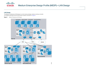
Medium Enterprise Design Profile (MEDP)—LAN DesignLAN DesignThe Medium Enterprise LAN design is a multi-campus design, where a campus consistsof multiple buildings and services at each location, as shown in Figure 1.Figure 1Medium Enterprise LAN DesignLarge BuildingMedium BuildingSmall BuildingExtra Small BuildingServicesBlockDataCenterInternetEdgeMain cesBlockDataCenterDataCenterDataCenterLarge BuildingMedium BuildingRemote Large SiteSmall BuildingMedium BuildingSmall BuildingRemote Medium Site229353Remote Small Site
Medium Enterprise Design Profile (MEDP)—LAN DesignFigure 2 shows the service fabric design model used in the medium enterprise LANdesign.Figure 2Medium Enterprise LAN DesignService Fabric Design ModelMobilitySecurityUnifiedCommunicationsLAN Design PrinciplesAny successful design or system is based on a foundation of solid design theory andprinciples. Designing the LAN component of the overall medium enterprise LAN servicefabric design model is no different than designing any large networking system. The useof a guiding set of fundamental engineering design principles serves to ensure that theLAN design provides for the balance of availability, security, flexibility, and manageabilityrequired to meet current and future advanced and emerging technology needs. Thischapter provides design guidelines that are built upon the following principles to allow amedium enterprise network architect to build enterprise campuses that are located indifferent geographical locations: HierarchicalLocal AreaNetwork (LAN)Wide AreaNetwork (WAN)228469– Facilitates understanding the role of each device at every tier– Simplifies deployment, operation, and managementThis chapter focuses on the LAN component of the overall design. The LAN componentconsists of the LAN framework and network foundation technologies that provide baselinerouting and switching guidelines. The LAN design interconnects several othercomponents, such as endpoints, data center, WAN, and so on, to provide a foundation onwhich mobility, security, and unified communications (UC) can be integrated into theoverall design.This LAN design provides guidance on building the next-generation medium enterprisenetwork, which becomes a common framework along with critical network technologiesto deliver the foundation for the service fabric design. This chapter is divided into followingsections: LAN design principles—Provides proven design choices to build various types ofLANs. LAN design model for the medium enterprise—Leverages the design principles ofthe tiered network design to facilitate a geographically dispersed enterprise campusnetwork made up of various elements, including networking role, size, capacity, andinfrastructure demands. Considerations of a multi-tier LAN design model for medium enterprises—Providesguidance for the enterprise campus LAN network as a platform with a wide range ofnext-generation products and technologies to integrate applications and solutionsseamlessly. Designing network foundation services for LAN designs in mediumenterprise—Provides guidance on deploying various types of Cisco IOStechnologies to build a simplified and highly available network design to providecontinuous network operation. This section also provides guidance on designingnetwork-differentiated services that can be used to customize the allocation ofnetwork resources to improve user experience and application performance, and toprotect the network against unmanaged devices and applications. – Reduces fault domains at every tierModularity—Allows the network to grow on an on-demand basis Resiliency—Satisfies user expectations for keeping network always onFlexibility—Allows intelligent traffic load sharing by using all network resourcesThese are not independent principles. The successful design and implementation of acampus network requires an understanding of how each of these principles applies to theoverall design. In addition, understanding how each principle fits in the context of theothers is critical in delivering a hierarchical, modular, resilient, and flexible networkrequired by medium enterprises today.Designing the medium enterprise LAN building blocks in a hierarchical fashion creates aflexible and resilient network foundation that allows network architects to overlay thesecurity, mobility, and UC features essential to the service fabric design model, as well asproviding an interconnect point for the WAN aspect of the network. The two proven,time-tested hierarchical design frameworks for LAN networks are the three-tier layer andthe two-tier layer models, as shown in Figure 3.
Medium Enterprise Design Profile (MEDP)—LAN DesignThree-Tier and Two-Tier LAN Design ModelsThree-TierLAN Design Core layerThe core layer is the network backbone that connects all the layers of the LAN design,providing for connectivity between end devices, computing and data storageservices located within the data center and other areas, and services within thenetwork. The core layer serves as the aggregator for all the other campus blocks, andties the campus together with the rest of the network.Two-TierLAN onFor more information on each of these layers, see the enterprise class networkframework at the following rprise/Campus/campover.html.Figure 4 shows a sample three-tier LAN network design for medium enterprises wherethe access, distribution, and core are all separate layers. To build a simplified,cost-effective, and efficient physical cable layout design, Cisco recommends building anextended-star physical network topology from a centralized building location to all otherbuildings on the same campus.Figure 4AccessThe key layers are access, distribution and core. Each layer can be seen as a well-definedstructured module with specific roles and functions in the LAN network. Introducingmodularity in the LAN hierarchical design further ensures that the LAN network remainsresilient and flexible to provide critical network services as well as to allow for growth andchanges that may occur in a medium enterprise. Access layerThe access layer represents the network edge, where traffic enters or exits thecampus network. Traditionally, the primary function of an access layer switch is toprovide network access to the user. Access layer switches connect to the distributionlayer switches to perform network foundation technologies such as routing, quality ofservice (QoS), and security.To meet network application and end-user demands, the next-generation CiscoCatalyst switching platforms no longer simply switch packets, but now provideintelligent services to various types of endpoints at the network edge. Buildingintelligence into access layer switches allows them to operate more efficiently,optimally, and securely. Building B –Marketingand Sales228470AccessThree-Tier LAN Network Design ExampleDistribution layerThe distribution layer interfaces between the access layer and the core layer toprovide many key functions, such as the following:– Aggregating and terminating Layer 2 broadcast domains– Aggregating Layer 3 routing boundaries– Providing intelligent switching, routing, and network access policy functions toaccess the rest of the network– Providing high availability through redundant distribution layer switches to theend-user and equal cost paths to the core, as well as providing differentiatedservices to various classes of service applications at the edge of networkBuilding C –EngineeringAccessDistributionBuilding A –ManagementCoreDistributionAccessBuilding D –Research andDevelopmentBuilding E –InformationTechnologyBuilding F –Data Center229354Figure 3The primary purpose of the core layer is to provide fault isolation and backboneconnectivity. Isolating the distribution and core into separate layers creates a cleandelineation for change control between activities affecting end stations (laptops, phones,and printers) and those that affect the data center, WAN, or other parts of the network. Acore layer also provides for flexibility in adapting the campus design to meet physical
Medium Enterprise Design Profile (MEDP)—LAN Designcabling and geographical challenges. If necessary, a separate core layer can use adifferent transport technology, routing protocols, or switching hardware than the rest ofthe campus, providing for more flexible design options when needed.In some cases, because of either physical or network scalability, having separatedistribution and core layers is not required. In smaller locations where there are less usersaccessing the network or in campus sites consisting of a single building, separate coreand distribution layers are not needed. In this scenario, Cisco recommends the two-tierLAN network design, also known as the collapsed core network design.Figure 5 shows a two-tier LAN network design example for a medium enterprise LANwhere the distribution and core layers are collapsed into a single layer.Figure 5Two-Tier Network Design ExampleAccessFloor 6 –Research and DevelopmentFloor 5 –EngineeringWANFloor 4 –ServerfarmFloor 2 loor 3 –Information TechnologyIf using the small-scale collapsed campus core design, the enterprise network architectmust understand the network and application demands so that this design ensures ahierarchical, modular, resilient, and flexible LAN network.Medium Enterprise LAN Design ModelsBoth LAN design models (three-tier and two-tier) have been developed with the followingconsiderations: Scalability—Based on Cisco enterprise-class high-speed 10G core switchingplatforms for seamless integration of next-generation applications required formedium enterprises. Platforms chosen are cost-effective and provide investmentprotection to upgrade network as demand increases. Simplicity—Reduced operational and troubleshooting cost via the use of Resilient—Sub-second network recovery during abnormal network failures or evennetwork-wide configuration, operation, and management.network upgrades. Cost-effectiveness—Integrated specific network components that fit budgetswithout compromising performance.As shown in Figure 6,multiple campuses can co-exist within a single medium enterprisesystem that offers various academic programs.
Medium Enterprise Design Profile (MEDP)—LAN DesignFigure 6Medium Enterprise LAN Design ModelHDTVIPMain Large SiteLarge BuildingMedium BuildingSmall BuildingCisco 6500VSSCUCM/UnitityACS/CSA-MCNAC MgrWCSVSOM/VSMSDMM/CVPDHCP/DNSNTTP/FTPNTPCisco 4500CoreDCExtra Small BuildingServiceBlockCisco 4500Cisco 3750StackwiseCisco 6500 VSSDMZWAEACNSWLCNACESAwwwASRWeb/EmailWSAInternet EdgeCisco 3800ASRGigaPOPMetroEHDLCPSTNInternetNLRHDLCCisco 2800Cisco 2800VSOM/VSMSWAE/ACNSDHCP/DNSNTTP/FTP/NTP WLC/NACDCApplianceBlockCisco 6500VSSLarge BuildingDCCisco 6500VSSCisco 4500Medium BuildingCisco 4500Small BuildingRemote Large SiteCisco 4500ApplianceBlockDCCisco 4500Medium BuildingCisco 3800VSOM/VSMSDHCP/DNS WAE/ACNSNTTP/FTP/NTP WLC/NACCisco 4500Small BuildingRemote Small SiteHDTVDepending on the remote campus office facility, the number of employees and thenetworked devices in remote campuses may be equal to or less than the main site.Campus network designs for the remote campus may require adjusting based on overallcampus capacity.Cisco 4500Small BuildingRemote Medium SiteIPApplianceBlockHDTVIP229355Cisco 375MEVSOM/VSMSWAE/ACNSDHCP/DNSNTTP/FTP/NTP WLC/NACUsing high-speed WAN technology, all the remote medium enterprise campusesinterconnect to a centralized main site that provides shared services to all the employeesindependent of their physical location. The WAN design is discussed in greater detail inthe next chapter, but it is worth mentioning in the LAN section because some remote sitesmay integrate LAN and WAN functionality into a single platform. Collapsing the LAN and
Medium Enterprise Design Profile (MEDP)—LAN DesignWAN functionality into a single Cisco platform can provide all the needed requirementsfor a particular remote site as well as provide reduced cost to the overall design, asdiscussed in more detail in the following section.Table 1 shows a summary of the LAN design models as they are applied in the overallmedium enterprise network design.The main site typically consists of various sizes of building facilities and variousorganization department groups. The network scale factor in the main site is higher thanthe remote campus site, and includes end users, IP-enabled endpoints, servers, andsecurity and network edge devices. Multiple buildings of various sizes exist in onelocation, as shown in Figure 8.Figure 8Table 1Main Site Reference DesignMedium Enterprise Recommended LAN Design ModelLargeBuildingMedium Enterprise Location Recommended LAN Design ModelMain campusThree-tierRemote large campusThree-tierRemote medium campusThree-tier with collapsed WAN edgeRemote small tributionMain Site Network DesignThe main site in the medium enterprise design consists of a centralized hub campuslocation that interconnects several sizes of remote campuses to provide end-to-endshared network access and services, as shown in Figure 7.Figure 7Main Site Reference Extra SmallBuildingData FPGigaPOPInternetNLR229356CoreData CenterBlockPSTNGatewayQFPPSTN228475WANEdgeThe three-tier LAN design model for the main site meets all key technical aspects toprovide a well-structured and strong network foundation. The modularity and flexibility ina three-tier LAN design model allows easier expansion and integration in the main sitenetwork, and keeps all network elements protected and available.To enforce external network access policy for each end user, the three-tier model alsoprovides external gateway services to the employees for accessing the Internet.Note The WAN design is a separate element in this location, because it requires aseparate WAN device that connects to the three-tier LAN model. WAN design isdiscussed in more detail in Chapter 3, “Medium Enterprise Design Profile(MEDP)—WAN Design.”
Medium Enterprise Design Profile (MEDP)—LAN DesignRemote Large Campus Site DesignFrom the location size and network scale perspective, the remote large site is not muchdifferent from the main site. Geographically, it can be distant from the main campus siteand requires a high-speed WAN circuit to interconnect both campuses. The remote largesite can also be considered as an alternate campus to the main campus site, with thesame common types of applications, endpoints, users, and network services. Similar tothe main site, separate WAN devices are recommended to provide application deliveryand access to the main site, given the size and number of employees at this location.Similar to the main site, Cisco recommends the three-tier LAN design model for theremote large site campus, as shown in Figure 9.Figure 10Remote Medium Campus Site Reference DesignAccessData CenterBlockRemote Large Campus Site Reference yPSTN228477Figure 9a three-tier large campus LAN design. All the LAN benefits are achieved in a three-tierdesign model as in the main and remote large site campus, and in addition, the platformchosen in the core layer also serves as the WAN edge, thus collapsing the WAN and coreLAN functionality into a single platform. Figure 10 shows the remote medium campus inmore detail.Remote Small Campus Network DesignCoreData EdgeRemote Medium Campus Site DesignRemote medium campus locations differ from a main or remote large site campus in thatthere are less buildings with distributed organization departments. A remote mediumcampus may have a fewer number of network users and endpoints, thereby reducing theneed to build a similar campus network to that recommended for main and largecampuses. Because there are fewer employees and networked devices at this site ascompared to the main or remote large site campus sites, the need for a separate WANdevice may not be necessary. A remote medium campus network is designed similarly toThe remote small campus is typically confined to a single building that spans acrossmultiple floors with different academic departments. The network scale factor in thisdesign is reduced compared to other large campuses. However, the application andservices demands are still consistent across the medium enterprise locations.In such smaller scale campus network deployments, the distribution and core layerfunctions can collapse into the two-tier LAN model without compromising basic networkdemands. Before deploying a collapsed core and distribution layer in the remote smallcampus network, considering all the scale and expansion factors prevents physicalnetwork re-design, and improves overall network efficiency and manageability.WAN bandwidth requirements must be assessed appropriately for this remote smallcampus network design. Although the network scale factor is reduced compared to otherlarger campus locations, sufficient WAN link capacity is needed to deliver consistentnetwork services to employees. Similar to the remote medium campus location, the WANfunctionality is also collapsed into the LAN functionality. A single Cisco platform canprovide collapsed core and distribution LAN layers. This design model is recommendedonly in smaller locations, and WAN traffic and application needs must be considered.Figure 11 shows the remote small campus in more detail.
Medium Enterprise Design Profile (MEDP)—LAN DesignRemote Small Campus Site Reference DesignMediumBuildingFigure 12Core Layer Design Models for Medium EnterprisesCore DesignOption – 1SmallBuildingSwitch-1AccessCisco Catalyst 6500DistributionCore DesignOption – 3Switch-2VSLCoreCore DesignOption – 2CollapsedCore/DistributionCoreCisco Catalyst 4500Cisco Catalyst 4500228478Figure 11Each design model offers consistent network services, high availability, expansionflexibility, and network scalability. The following sections provide detailed design anddeployment guidance for each model as well as where they fit within the various locationsof the medium enterprise design.Core Layer Design Option 1—Cisco Catalyst 6500-E-Based Core Core layer design option 1 is specifically intended for the main and remote large sitecampus locations. It is assumed that the number of network users, high-speed andlow-latency applications (such as Cisco TelePresence), and the overall network scalecapacity is common in both sites and thus, similar core design principles are required.Core layer design option 1 is based on Cisco Catalyst 6500 Series switches using theCisco Virtual Switching System (VSS), which is a software technology that builds a singlelogical core system by clustering two redundant core systems in the same tier. Building aVSS-based network changes network design, operation, cost, and managementdramatically. Figure 13 shows the physical and operational view of VSS.Figure 13Virtual Switch DomainVSLMulti-Tier LAN Design Models for Medium EnterpriseThe previous section discussed the recommended LAN design model for each mediumenterprise location. This section provides more detailed design guidance for each tier inthe LAN design model. Each design recommendation is optimized to keep the networksimplified and cost-effective without compromising network scalability, security, andresiliency. Each LAN design model for a medium enterprise location is based on the keyLAN layers of core, distribution, and access.Campus Core Layer Network DesignAs discussed in the previous section, the core layer becomes a high-speed intermediatetransit point between distribution blocks in different premises and other devices thatinterconnect to the data center, WAN, and Internet edge.Similarly to choosing a LAN design model based on a location within the mediumenterprise design, choosing a core layer design also depends on the size and locationwithin the design. Three core layer design models are available, each of which is based oneither the Cisco Catalyst 6500-E Series or the Cisco Catalyst 4500-E Series Switches.Figure 12 shows the three core layer design models.VSS Physical and Operational ViewSwitch-1Switch-2VSS – SingleLogical Switch228479CoreData CenterBlockTo provide end-to-end network access, the core layer interconnects several other networksystems that are implemented in different roles and service blocks. Using VSS tovirtualize the core layer into a single logical system remains transparent to each networkdevice that interconnects to the VSS-enabled core. The single logical connectionbetween core and the peer network devices builds a reliable, point-to-point connectionthat develops a simplified network topology and builds distributed forwarding tables tofully use all resources. Figure 14 shows a reference VSS-enabled core network design forthe main campus site.
Medium Enterprise Design Profile (MEDP)—LAN DesignVSS-Enabled Core Network DesignLargeBuildingMediumBuildingFigure 15SmallBuildingRemote Medium Campus Core Network DesignExtra nDistributionCoreInternet Edge BlockData CenterBlockVSLShared Service ceBlockQFPWANEdgeGigapopInternetData ldingFor more detailed VSS design guidance, see the Campus 3.0 Virtual SwitchingSystem Design Guide at the following rprise/Campus/VSS30dg/campusVSS DG.html.Core Layer Design Option 2—Cisco Catalyst 4500-E-Based Campus Core NetworkCore layer design option 2 is intended for a remote medium-sized campus and is built onthe same principles as for the main and remote large site campus locations. The size ofthis remote site may not be large, and it is assumed that this location contains distributedbuilding premises within the remote medium campus design. Because this site is smallerin comparison to the main and remote large site campus locations, a fully redundant,VSS-based core layer design may not be necessary. Therefore, core layer design option2 was developed to provide a cost-effective alternative while providing the samefunctionality as core layer design option 1. Figure 15 shows the remote medium campuscore design option in more detail.WANPSTN228481Figure 14The cost of implementing and managing redundant systems in each tier may introducecomplications in selecting the three-tier model, especially when network scale factor isnot too high. This cost-effective core network design provides protection against varioustypes of hardware and software failure and offers sub-second network recovery. Insteadof a redundant node in the same tier, a single Cisco Catalyst 4500-E Series Switch can bedeployed in the core role and bundled with 1 1 redundant in-chassis networkcomponents. The Cisco Catalyst 4500-E Series modular platform is a one-size platformthat helps enable the high-speed core backbone to provide uninterrupted networkaccess within a single chassis. Although a fully redundant, two-chassis design using VSSas described in core layer option 1 provides the greatest redundancy for large-scalelocations, the redundant supervisors and line cards of the Cisco Catalyst 4500-E provideadequate redundancy for smaller locations within a single platform. Figure 16 shows theredundancy of the Cisco Catalyst 4500-E Series in more detail.
Medium Enterprise Design Profile (MEDP)—LAN DesignFigure 16Highly Redundant Single Core Design Using the Cisco Catalyst 4500-E PlatformCoreRedundantSupervisorRedundantPower CycleRedundantLine CardsSingle highly resilient Cisco Catalyst 4500-E switches with a Cisco Sup6L-E supervisormust be deployed in a centralized collapsed core and distribution role that interconnectsto wiring closet switches, a shared service block, and a WAN edge router. Thecost-effective supervisor version supports key technologies such as robust QoS, highavailability, security, and much more at a lower scale, making it an ideal solution forsmall-scale network designs. Figure 17 shows the remote small campus core design inmore detail.DiversedFiber Paths228482DistributionThis core network design builds a network topology that has similar common designprinciples to the VSS-based campus core in core layer design option 1. The futureexpansion from a single core to a dual VSS-based core system becomes easier to deploy,and helps retain the original network topology and the management operation. Thiscost-effective single resilient core system for a medium-size enterprise network meetsthe following four key goals: Figure 17Core Layer Option 3 Collapsed Core/Distribution Network Design in Remote SmallCampus ty—The modular Cisco Catalyst 4500-E chassis enables flexibility for corenetwork expansion with high throughput modules and port scalability withoutcompromising network performance.Resiliency—Because hardware or software failure conditions may createcatastrophic results in the network, the single core system must be equipped withredundant system components such as supervisor, line card, and power supplies.Implementing redundant components increases the core network resiliency duringvarious types of failure conditions using Non-Stop Forwarding/Stateful Switch Over(NSF/SSO) and EtherChannel technology.Simplicity—The core network can be simplified with redundant network modulesand diverse fiber connections between the core and other network devices. TheLayer 3 network ports must be bundled into a single point-to-point logicalEtherChannel to simplify the network, such as the VSS-enabled campus design. AnEtherChannel-based campus network offers similar benefits to an Multi-chassisEtherChannel (MEC)- based network.Cost-effectiveness—A single core system in the core layer helps reduce capital,operational, and management cost for the medium-sized campus network design.Core Layer Design Option 3—Cisco Catalyst 4500-E-Based Collapsed CoreCampus NetworkCore layer design option 3 is intended for the remote small campus network that hasconsistent network services and applications service-level requirements but at reducednetwork scale. The remote small campus is considered to be confined within a singlemulti-story building that may span academic departments across different floors. Toprovide consistent services and optimal network performance, scalability, resiliency,simplification, and cost-effectiveness in the small campus network design must not becompromised.DistributionShared Service BlockCoreData 8481 As discussed in the previous section, the remote small campus has a two-tier LAN designmodel, so the role of the core system is merged with the distribution layer. Remote smallcampus locations have consistent design guidance and best practices defined for main,remote large site, and remote medium-sized campus cores. However, for platformselection, the remote medium campus core layer design must be leveraged to build thistwo-tier campus core.Campus Distribution Layer Network DesignThe distribution or aggregation layer is the network demarcation boundary betweenwiring-closet switches and the campus core network. The framework of the distributionlayer system in the medium enterprise design is based on best practices that reduce
Medium Enterprise Design Profile (MEDP)—LAN Designnetwork complexities and accelerate reliability and performance. To build a strongcampus network foundation with the three-tier model, the distribution layer has a vital rolein consolidating networks and enforcing network edge policies.The following the core layer design options in different campus locations, the distributionlayer design provides consistent network operation and configuration tools to enablevarious network services. Three simplified distribution layer design options can bedeployed in main or remote campus locations, depending on network scale, applicationdemands, and cost, as shown in Figure 18. Each design model offers consistent networkservices, high availability, expansion flexibility, and network scalability. A single logical system reduces operational, maintenance, and ownership cost.A single logical IP gateway develops a unified point-to-point network topology in thedistribution block, which eliminates traditional protocol limitations and enables thenetwork to operate at full capacity. Implementing the distribution layer in VSS mode eliminates or reduces severaldeployment barriers, such as spanning-tree loop, Hot Standby Routing Protocol(HSRP)/Gateway Load Balancing Protocol (GLBP)/Virtual Router RedundancyProtocol (VRRP), and control plane overhead.Distribution Layer Design Model OptionsSwitch-1Design Option – 2AccessCisco VSS introduces unique inter-chassis traffic engineering to develop afully-distributed forwarding design that helps in increased bandwidth, loadbalancing, predictable network recovery, and network stability.Deploying VSS mode in both the distribution layer switch and core layer switch providesnumerous technology deployment options that are not available when not using VSS.Designing a common core and distribution layer option using VSS provides greaterredundancy and is able to handle the amount of traffic typically present in the main andremote large site campus locations. Figure 20 shows five unique VSS domaininterconnect options. Each variation builds a unique network topology that has a directimpact on steering traffic and network recovery. Switch-2VSLDistributionDesign Option – 3DistributionDistributionAc
LAN design principles—Provides proven design choices to build various types of LANs. LAN design model for the medium enterprise—Leverages the design principles of the tiered network design to facilitate a geographically dispersed enterprise campus network made up of various