Transcription
Deployment GuideVersion 1.2Deploying the BIG-IP GTM for DNSSECWhat’s inside:2Configuration options5ConfiguringAuthoritative Screeningmode5Screening mode forGlobal Server LoadingBalancing11 Configuring DNS loadbalancing only mode12 Configuring Delegationmode13 Configuring the BIG-IPGTM for DNSSECWelcome to the F5 Deployment Guide for DNSSEC with Global Traffic Manager (GTM). This guideshows how to configure Authoritative DNSSEC signing for a zone in front of a pool of DNS servers,to sign responses from virtual servers in a global server load balancing configuration, or to do bothin Authoritative Screening mode.DNSSEC is a extension to the Domain Name Service (DNS) that ensures the integrity of datareturned by domain name lookups by incorporating a chain of trust in the DNS hierarchy. The basisof DNSSEC is public key cryptography (PKI). A chain of trust is built with public-private keys at eachlayer of the DNS architecture.DNSSEC provides origin authenticity, data integrity and secure denial of existence. Specifically, OriginAuthenticity ensures that resolvers can verify that data has originated from the correct authoritativesource. Data Integrity verifies that responses are not modified in-flight and Secure Denial ofExistence ensures that when there is no data for a query, that the authoritative server can provide aresponse that proves no data exists.This guide explains how to configure DNSSEC in BIG-IP Global Traffic Manager. For moreinformation on the F5 BIG-IP GTM, c-manager.html15 DNSSEC IntegrationVerificationTo provide feedback on this deployment guide or other F5 solution documents, contact us atsolutionsfeedback@f5.com.16 Document RevisionHistoryProducts and versions testedProductVersionBIG-IP GTM/LTM10.2.1 and laterImportant: M ake sure you are using the most recent version of this deployment guide, available ec-dgPrerequisites and configuration notesThe following are general prerequisites and configuration notes for this guide:hh You must be running BIG-IP version 10.2.1 or later.hh Y ou must have the BIG-IP GTM licensed, either as a standalone device, or a module onthe BIG-IP system. For DNSSEC, you must also have the DNSSEC add-on license.
DEPLOYMENT GUIDEDNSSEChh W hile not required for this configuration, we also strongly recommend using the BIG-IPLocal Traffic Manager (LTM) as described in this document.hh Y ou must have administrative access to both the Web management and SSH commandline interfaces on the BIG-IP system.hh T he BIG-IP system must be initially configured with the proper VLANs and Self IPaddresses. For more information on VLANs and Self IPs, see the online help or the BIG-IPdocumentation.hh You must have administrative control of the DNS zone being protected.hh I f there are firewalls, you must have TCP port 443 open in both directions. TCP port22 for SSH access to the command line interface is also needed for configurationverification.hh F or more configuration options on the BIG-IP GTM, see the Configuration Guide for BIGIP GTM Module, available on Ask F5.hh W e recommend you read the Technical Brief F5 and Infoblox DNS Integrated foblox-wp.pdf) for a configuration overview.Even if you are not using Infoblox, this brief provides detailed information on theconcepts found in this deployment guide.hh W e recommend you read the NIST Secure Domain Name System Deployment 00-81r1/sp-800-81r1.pdf). We use the NISTrecommended values in this guide.Configuration optionsThere are three main ways to configure the BIG-IP GTM system for DNSSEC shown in this guide.The method you choose depends on your configuration and whether you are also using the BIG-IPLTM. uthoritative Screening modeAThe Authoritative Screening architecture enables BIG-IP GTM to receive all DNS queries, managingvery high-volume DNS by load balancing requests to a pool of DNS servers. Additionally, theAuthoritative Screening architecture seamlessly provides all of the benefits of intelligent GSLBservices.When a DNS query is received, the BIG-IP checks the record type. If the type is an A, AAAA, A6,or CNAME request, it is sent to BIG-IP GTM module. The BIG-IP GTM checks each request andresponse, looking for a match against the wide IP (WIP) list of FQDN names. If there is a match, theBIG-IP GTM performs the appropriate GSLB functions and return the best IP address appropriate forthe requesting client.If the DNS request does not match the Wide IP list, BIG-IP GTM passes the request to a pool ofDNS servers, which provides an additional layer of scalability and availability, increasing the queryperformance and ensuring optimal uptime of DNS services. Screening mode simplifies managementwhen used with InfoBlox DNS servers (see the Technical Brief mentioned above).GTM inspects all DNS responses from the DNS servers. If the response contains a DNS name thatmatches a Wide IP, GTM intercepts the response, applies the GTM operations for that item, andre-writes the response before sending it on to the client.2
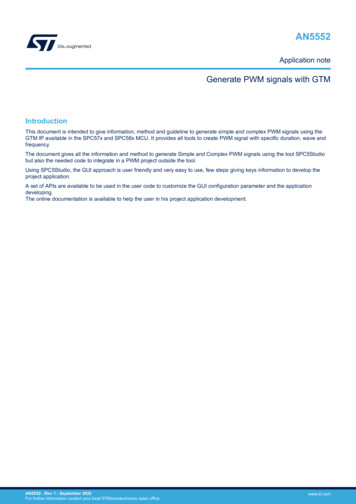
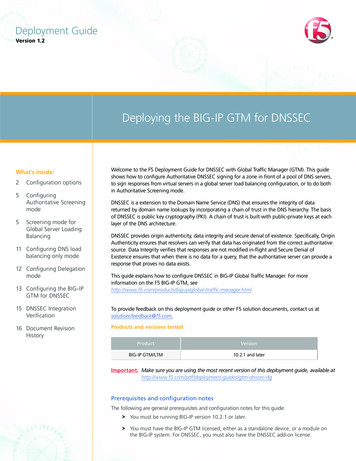
DEPLOYMENT GUIDEDNSSECClientClientClient1243BIG-IPGlobal Traffic Managerwith DNSSECcompany.comFigure 1: Authoritative screening mode with DNS load balancingThe following describes the traffic flow for Authoritative Screening:1. The client, via LDNS, requests the MX record for company.com.2.The BIG-IP GTM asks the DNS server pool for the MX record3.The DNS server responds to the MX record request with mail.company.com.4.T he BIG-IP GTM matches a wide IP for mail.company.com. The GTM responds to the clientrequest with mail.company.com and adds the IP address of the mail server. GTM adds theDNSSEC signature.DNS Load BalancingYou can also use only the DNS load balancing components of screening mode to sign responsesfrom 3rd-party DNS servers. This saves time by using F5’s DNSSEC rather than signing the DNSzones manually.DelegationDelegation has been the traditional deployment method. This solution involves delegating aspecific subzone that contains all the GSLB elements of the DNS architecture. In this scenario, aCNAME is used to redirect other names to one located in the delegated subzone. One drawbackwith delegation mode is that the administrator is required to create a CNAME for all related DNSrecords.In this example, the DNS servers completely manage the top-level zone (such as example.com).The NS records point to the names and, indirectly, the IP address of the DNS servers . BIG-IP GTM isauthoritative for a subzone and handles all queries to that zone (for instance, gtm.example.com).All GSLB resources are represented by A-records in the GTM zone. A BIND name server runningon BIG-IP GTM contains the subzone records. Host names in the top-level zone are referred to theGTM-controlled subzone using CNAME alias records. CNAME references can be from almost anyother zone, including the subzone. More than one subzone can be delegated to and managed byGTM zone.3
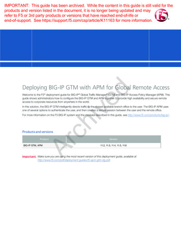
DEPLOYMENT GUIDEDNSSECClientClient1Client34BIG-IPGlobal Traffic Managerwith DNSSEC2company.comFigure 2:Delegation modeThe following describes the traffic flow for delegation:41.Client requests www.company.com.2.T he DNS server that owns www.company.com returns a CNAME for www.company.com towww.gtm.company.com.3.The local DNS requests www.gtm.company.com.4.T he BIG-IP GTM has the wide IP and owns the gtm subzone. The GTM handles DNSSEC forthe subzone only. The GTM responds with the best IP address based on the load balancingconfiguration for the pool.
DEPLOYMENT GUIDEDNSSECConfiguring Authoritative Screening modeIn this section, we configure the BIG-IP for Authoritative Screening mode. Some of the proceduresin this section depend on whether you are using a BIG-IP LTM in front of a pool of DNS servers.Screening mode for Global Server Loading BalancingUse the following procedures to configure screening mode for GSLB.Configuring a GTM ListenerThe first task is to create a Listener on the BIG-IP GTM. A listener is an object that monitors thenetwork for DNS queries.To create a Listener1. n the Main tab of the navigation pane, expand Global Traffic and then click Listeners.OThe main Listeners screen opens.2.Click the Create button. The new Listener screen opens.3. In the Destination box, type the IP address on which the Global Traffic Manager listens fornetwork traffic. In our example, this is the Self IP address of the GTM on the internal VLAN.Important Be sure to use a Self IP address and not the Management address of the BIG-IP GTM.4.From the VLAN Traffic list, select a VLAN setting appropriate for this listener.5.Click the Finished button.Creating the GTM Data CenterThe next task is to create a new GTM Data Center that corresponds to your physical data center.To create the data center1. On the Main tab, expand Global Traffic and then click Data Centers.2.Click the Create button. The New Data Center screen opens.3. In the Name box, type a name for this data center. In our example, we typeLocal Datacenter.4.Complete the rest of the configuration as applicable for your deployment.5.Click the Finished button.Creating the GTM Server objectsNext, we create the GTM Servers. A server defines a specific system on the network.The steps in this procedure are slightly different if you are using a standalone GTM device orthe GTM module in combination with a BIG-IP LTM. These differences are clearly marked in thefollowing procedures.ImportantYou must add a Server object for the BIG-IP GTM you are currently configuring and every GTM thatis a part of the sync group. For more information on GTM sync groups, see the online help or GTMdocumentation.To create the GTM servers51. On the Main tab, expand Global Traffic and then click Servers.2.Click the Create button. The New Server screen opens.3. In the Name box, type a name that identifies this GTM. In our example, we type GTM-1.
DEPLOYMENT GUIDEDNSSEC4. From the Product list, select the either BIG-IP System (Single) or BIG-IP System(Redundant).5. In the Address List section, type the self IP of this GTM, and then click the Add button.ImportantBe sure to use a Self IP address and not the Management address of the BIG-IP GTM.If you selected BIG-IP System (Redundant) in step 4, type the appropriate IP address in thePeer Address List section.6. From the Data Center list, select the Data Center you created in Creating the GTM DataCenter on page 5. In our example, we select Local Datacenter.7. Optional: In the Health Monitors section, from the Available list, select the monitor typebigip and then click the Add ( ) button.8. From the Virtual Server Discovery list, perform the following depending on whether youare using a third party load balancer, or a remote BIG-IP LTM:9. Third Party Load Balancer: Leave Discovery set to Disabled. TM Module: From the Discovery list, select Enabled. (We strongly recommend EnablingGDiscovery, however you can leave this set to Disabled and manually configure the virtualserver information).Click Finished.10. The next step depends on your configuration: I f you have additional BIG-IP GTMs in your implementation, repeat this procedure to addthem. I f you are using the GTM and LTM on the same box, continue with the next section.However, if there are external BIG-IP LTM devices that are a part of the configuration, youmust add a GTM Server object for those as well. Repeat this procedure for each externalLTM. I f you are using a GTM standalone, repeat this procedure to create the GTM Serverobjects for each of the load balancers (a BIG-LTM in our example) and continue with step10.Enabling connectivity with remote BIG-IP systemsIf you are adding a remote BIG-IP LTM server, you must make sure big3d agent on the sameversion on the BIG-IP LTM and GTM.ImportantThis is only necessary if you are using remote LTM devices.From the GTM device command line, typebig3d install IP address of target system where the target system is the LTM that you want to add as a server on the GTM. This pushes outthe newest version of big3d.Next, typebigip addto exchange SSL keys with the LTM. Type the password at the prompt, and then typeiqdump ip address of remote box .If the boxes are communicating over iQuery, you see a list of configuration information from theremote BIG-IP.The bigip add command must be run for every BIG-IP in the configuration.6
DEPLOYMENT GUIDEDNSSECAdding GTM servers to a Sync GroupYou must run gtm add on each additional GTM in the sync group as well to ensure the iQueryconfiguration is working. If not already part of a sync group, this command adds the GTM to thesync group. For more information on sync groups, see the GTM documentation.Creating the GTM health monitorsThe next task is to create the GTM health monitors. If you are using the BIG-IP LTM, status from theLTM monitors will be available in the GTM. The following GTM monitors add an additional layer ofmonitoring that is initiated by the GTM. While health monitors are not technically required, theyare strongly recommended. The monitors shown in the following sections are examples, you canuse other monitor types appropriate to your deployment.To create the TCP and HTTP monitors1.On the Main tab, expand Global Traffic and then click Monitors.2.Click the Create button. The New Monitor screen opens.3. In the Name box, type a name for the monitor. In our example, we typegtm-monitor-tcp.4.From the Type list, select TCP.5.From the Configuration list, select Advanced.6.Configure any of the other options as applicable for your implementation.7.Click the Repeat button to create another monitor for HTTP.8. In the Name box, type a name for this monitor. In our example we named itgtm-monitor-http.9.From the Type list, select HTTP.10. Configure the other options as applicable for your implementation.11. Click the Finished button.Creating the GTM PoolFirst, we create a pool on the BIG-IP GTM system that includes the virtual servers of load balancingdevice (BIG-IP LTM in our example).To create a GTM pool1. On the Main tab, expand Global Traffic and then click Pools (located under Wide IPs).2.Click the Create button. The New Pool screen opens.3.In the Name box, type a name for the pool. In our example, we type Local pool.4. In the Health Monitors section, from the Available list, select the name of the monitors youcreated in Creating the GTM health monitors on page 7, and then click the Add ( )button after each. In our example, we select gtm-monitor-tcp and gtm-monitor-http.5. In the Load Balancing Method section, choose the load balancing methods from the listsappropriate for your configuration.6. In the Member List section, from the Virtual Server list, select the appropriate virtual serveron the load balancer for the application, and then click the Add button. ote that you must select the virtual server by IP Address and port number combination. InNour example, we select 10.10.11.3:80.Repeat this step for additional virtual servers.7
DEPLOYMENT GUIDEDNSSEC7.Configure the other settings as applicable for your deployment8.Click the Finished button.Creating the GTM Wide IPIn this procedure, we create a wide IP that includes the GTM pool you created, and the hostname . In our example, we use www.example.com. GTM attempts to match DNS requestsand responses to the resource indicated by the Wide IP.To create a wide IP1. On the Main tab, expand Global Traffic and then click Wide IPs.2.Click the Create button. The New Wide IP screen opens.3. In the Name box, type a name for the Wide IP. In screening mode, this is the FQDN of thehost. In our example, we type www.example.com.4.From the State list, ensure that Enabled is selected.5. From the Pools section, from the Load Balancing Method list, select a load balancingmethod appropriate for your configuration.6. In the Pool List section, from the Pool list, select the name of the pool you created inCreating the GTM Pool on page 7, and then click the Add button. In our example, weselect Local pool.7.All other settings are optional, configure as appropriate for your deployment.8.Click the Finished button.Configuring the GTM for DNSSECIf you are not planning to use DNS load balancing in your configuration as described in thefollowing section, continue to Configuring the BIG-IP GTM for DNSSEC on page 13.ImportantAdding DNS load balancing to Screening mode for GSLBUse the following procedures to add DNS Load Balancing to Screening mode for GSLB.Creating the LTM monitorsIf you are using the BIG-IP LTM, configure the following monitors. These monitors test the serversto ensure the DNS services are operational. DNS is available over UDP and TCP protocols, so wecreate a health monitor for each protocol over port 53. If you only choose to implement onemonitor, we recommend the UDP monitor.To create the LTM monitors81.On the Main tab, expand Local Traffic and then click Monitors.2.Click the Create button. The New Monitor screen opens.3. In the Name box, type a name for the monitor. In our example, we typeltm-dns-monitor-tcp.4.From the Type list, select TCP.5.From the Configuration list, select Advanced.6.In the Alias Service Port box, type 53.7.Configure any of the other options as applicable for your implementation.
DEPLOYMENT GUIDEDNSSEC8.Click the Repeat button to create another monitor for UDP.9. In the Name box, type a name for this UDP monitor. In our example we named itltm-dns-monitor-udp.10. From the Type list, select UDP.11. Make sure the Alias Service Port box is set to 53.12. Configure the other options as applicable for your implementation.13. Click the Finished button.Creating the LTM poolThe next task is to create a pool on the Local Traffic Manager for the DNS servers.To create a LTM pool1.On the Main tab, expand Local Traffic, and then click Pools.2.Click the Create button.3. In the Name box, type a unique name for this Pool.4. In the Health Monitors section, from the Available list, select the name of the monitor youcreated in Creating the LTM monitors on page 8, and then click the Add ( ) button aftereach. In our example, we select ltm-dns-monitor-tcp and ltm-dns-monitor-tcp.5.I n the Resources section, from the Load Balancing Method list, choose your preferred loadbalancing method (different load balancing methods may yield optimal results for a particularnetwork).6.In the New Members section, you add the DNS servers to the pool.a. In the Address box, type the IP address of one of the DNS servers.b. In the Service Port box, type 53.c. Click the Add button to add the member to the list.d. Repeat steps a-c for each device you want to add to the pool.7.Click the Finished button.Attaching the pool to the GTM ListenerThe next task is to attach the LTM pool to the GTM Listener. This procedure can be performed fromthe TMSH command line or the Configuration utility. If you choose to use the Configuration utility,you must have LTM provisioned (even if you are using a GTM standalone, you can use ResourceProvisioning to set the LTM to minimal without a full LTM license).An addition command in step 4 configures the GTM Listener for SNAT and IP translation.To attach the pool to the Listener using the command line1.Log on to the GTM and open a command prompt.2.At the prompt, type tmsh.3.T ype the following command, replacing listener name and ltm pool name with thename of your Listener and Pool:modify /ltm virtual listener name pool ltm pool name 4.Type the following command:modify /ltm virtual listener name snat automap translate-address enabled9
DEPLOYMENT GUIDEDNSSECTo attach the pool to the Listener using the Configuration utility1. n the Main tab, expand Local Traffic, and then click Virtual Servers. As mentioned inOthe introduction to this section, you must have LTM provisioned to see the virtual server.2. lick the virtual server name that was automatically created for the Listener. This virtual serverCname includes the IP address you used for the Listener, starting with vs and ending withgtm. For example, vs 10 1 102 5 53 gtm.3.From the Configuration list, select Advanced.4.From the SNAT Pool list, select Automap.5. From the Address Translation row, click a check in the Enabled box to enable AddressTranslation.6.Click Update.7.On the Menu bar, click Resources.8.From the Default Pool list, select the name of your LTM pool.9.Click Update.Configuring the GTM for DNSSECWhen you have finished the preceding configuration, continue to Configuring the BIG-IP GTM forDNSSEC on page 13.Important10
DEPLOYMENT GUIDEDNSSECConfiguring DNS load balancing only modeIn this section, we configure the BIG-IP for DNS Load Balancing mode without the components ofGSLB described in the first section. After the BIG-IP has been initially configured, we configure theDNSSEC components.Because this mode uses some of the same objects as in screening mode, we refer back to theprocedures in the previous section instead of repeating the information.Configuring a GTM ListenerTo configure the GTM Listener, follow the procedure Configuring a GTM Listener on page 5with no modifications.Configuring the LTM monitorsThe next task is to create the LTM health monitors. To configure the monitors, follow theprocedure Creating the LTM monitors on page 10 with no modifications.Configuring the LTM poolThe next task is to create the LTM health monitors. To configure the monitors, follow theprocedure Creating the LTM pool on page 10 with no modifications.Attaching the pool to the GTM ListenerThe next task is to attach the LTM pool to the GTM Listener. To attach the pool to the Listener,follow the procedure Attaching the pool to the GTM Listener on page 9.Configuring the GTM for DNSSECImportantWhen you have finished the preceding configuration, continue to Configuring the BIG-IP GTM forDNSSEC on page 13.11
DEPLOYMENT GUIDEDNSSECConfiguring Delegation modeIn this section, we configure the BIG-IP for Delegation mode. After the BIG-IP has been initiallyconfigured, we configure the DNSSEC components.Because this mode uses some of the same objects as in screening mode, we refer back to theprocedures in the previous section instead of repeating the information.Configuring a GTM ListenerTo configure the GTM Listener, follow the procedure Configuring a GTM Listener on page 5with no modifications.Configuring the Data CenterThe next task is to create the GTM Data Center. To configure the Data Center, follow the procedureCreating the GTM Data Center on page 5 with no modifications.Configuring the Wide IPThe next task is to create the Wide IP. To configure the Wide IP, follow the procedure Creating theGTM Wide IP on page 8. This Wide IP must be the new CNAME the DNS server refers to in thesubzone assigned to the GTM. For example gtm.example.com. For example, if the GTM ownsgtm.example.com, the CNAME for www.example.com may redirect the query to www.gtm.example.comBecause the GTM will be entirely responsible for managing the subzone, all of the other records forthe subzone (NS, SOA, and so on) need to be added to the local BIND configuration on the GTMusing ZoneRunner. Note that the NS record needs to point to the address of the GTM Listener.For information on configuring ZoneRunner, see the online help or GTM documentation.Configuring the GTM for DNSSECImportantWhen you have finished the preceding configuration, continue to Configuring the BIG-IP GTM forDNSSEC on page 13.12
DEPLOYMENT GUIDEDNSSECConfiguring the BIG-IP GTM for DNSSECDeploying DNSSEC involves signing DNS zones with public/private key encryption andreturning DNS signed responses. A client trust for the signatures is based on a chain of trustestablished across administrative boundaries.In this section, we configure the global traffic settings on the BIG-IP GTM.Before beginning the configuration in this section, you should have configured the BIG-IPGTM as described in one of the scenarios in this guide.ImportantAny zone that contains a Wide IP name in the GTM configuration must be signed by F5.WarningsIf GTM is not properly configured with data centers and GTM devices defined, and theDNSSEC license, key generation will fail.If you are using DNS load balancing or BIND, you should never sign the responses with theback end DNS servers if you are going to sign them using GTM.Creating the Key Signing KeyThe first task in this section is to create the Key Signing Key on the GTM.To create the Key Signing Key1. On the Main tab, expand Global Traffic and then click DNSSEC Key List.2.Click the Create button.3. In the Name box, type the domain name. In our example, we typeexample.com ksk.4. In the BIT Width box, we recommend you type a larger value for the Key Signing Keybecause it is the master key. In our example, we change the default value of 1024 to2048.5. Optional: If you have a BIG-IP FIPS hardware security module installed in your BIG-IPdevice, you have the option of storing this key on the hardware device. If so, from theUse FIPS list, select Enabled. If you are unsure if you have this module, consult withyour F5 Sales Representative.6.From the Type list, select Key Signing Key.7. In the Rollover Period row, we recommend a rollover set to 185 days. While the NiSTstandard for rollover is 180 days, the BIG-IP requires a rollover that is at least half of theExpiration (365 in our example). In the Days box, we type 185.8. In the Expiration Period row, we recommend 1 year, the NiST standard for expiration.In the Days box, we type 365.9. Click the Finished button (see Figure 3).Creating the Zone Signing KeyThe next task is to create the Zone Signing Key.To create the Zone Signing Key131. On the Main tab, expand Global Traffic and then click DNSSEC Key List.2.Click the Create button.
DEPLOYMENT GUIDEDNSSEC3.In the Name box, type the domain name. In our example, we type example.com zsk.4. Optional: If you have a BIG-IP FIPS hardware security module installed in your BIG-IPdevice, you have the option of storing this key on the hardware device. If so, from theUse FIPS list, select Enabled. If you are unsure if you have this module, consult withyour F5 Sales Representative.5.From the Type list, select Zone Signing Key.6. In the Rollover Period row, we recommend a rollover set to 15 days, the NiSTstandard for rollover. In the Days box, we type 15.7. In the Expiration Period row, we recommend 30 days, the NiST standard forexpiration. In the Days box, we type 30.8.We recommend you leave the other settings at the defaults.9.Click the Finished button.Protecting the ZonesNext, we protect the zones with the zone signing keys.To protect the zones1.On the Main tab, expand Global Traffic, click DNSSEC Zone List.2.Click the Create button.3.In the Name box, type a name for this zone. In our example, we use example.com.4. In the Zone Signing Key section, from the Available box, click the Zone Signing Keyyou created, and then click the Add ( ) button. In our example, we selectexample.com zsk.5. In the Key Signing Key section, from the Available box, click the Key Signing Key youcreated, and then click the Add ( ) button. In our example, we selectexample.com ksk.6.Click Finished.You have now protected your Zone with DNSSEC.Providing the DNSSEC DS Record to the parent domainOne of the steps in configuring DNSSEC on the BIG-IP GTM system involves establishingan authentication chain between the parent and child DNSSEC zones. When you create aDNSSEC zone, or renew keys for an existing DNSSEC zone, you must provide the DelegationSigner (DS) Resource Record(s) to the parent domain. Providing the DS record to the parentdomain establishes the authentication chain between the parent and child DNS zones,allowing each link in the chain to vouch for the next. Without a complete authenticationchain, an answer to a DNS lookup cannot be securely authenticated.For detailed configuration instructions, see Ask F5 public/12000/900/sol12981.html14
DEPLOYMENT GUIDEDNSSECDNSSEC Integration VerificationThe final task is to verify the configuration is operating properly. We use a test client to accessthe GTM Wide IP to perform DNS lookup requests. A DNS client application called Dig can beused to query the DNS Server.Launch a terminal application and issue a request that includes DNSSEC, such as:dig @bigip10.siterequest.com dnssec multiline www.dnssec.f5demo.comYou see a result similar to the following example:; DiG 9.6.0-APPLE-P2 @bigip10.siterequest.com dnssec multiline www.dnssec.f5demo.com; (1 server found);; global options: cmd;; Got answer:;; - HEADER - opcode: QUERY, status: NOERROR, id: 60496;; flags: qr aa rd ad; QUERY: 1, ANSWER: 6, AUTHORITY: 0, ADDITIONAL: 1;; WARNING: recursion requested but not available;; OPT PSEUDOSECTION:; EDNS: version: 0, flags: do; udp: 4096;; QUESTION SECTION:;www.dnssec.f5demo.com.IN A;; ANSWER SECTION:www.dnssec.f5demo.com.30 IN Awww.dnssec.f5demo.com.30 IN RRSIG A 7 4 30 20100116005323 (20100109005323 31052 fcAAnhxkiYCNus 0TYKoRwXfGKOdNJd/WjrcD I )www.dnssec.f5demo.com.30 IN RRSIG A 7 4 30 20100116005323 (20100109005323 61232 dnssec.f5demo.com.vJS aZIH8ya4UD8Ar/V yJjrPxA2ShK/nhlW4t81/R njx1MJoZ9a71Y8cHMqXLpYgEpYXVHY7OJ akp833oYbFbMVg7YbnYEItNUEM 6LuitXo89FUTaY2QI )www.dnssec.f5demo.com.30 IN RRSIG A 7 4 30 20100116005323 (20100109005323 46472 dnssec.f5demo.com.fdio5eNraa1eBM PSd3a ANcbr869vsJ9F4DSs9CfbVJdOkaGFqPYwjWpqMLxN/B1aHlNpw )www.dnssec.f5demo.com.30 IN RRSIG A 7 4 30 20100116005323 (20100109005323 64235 dnssec.f5demo.com.7cpHDxhdqAips rLTpprDnjSJc j83/zPOR
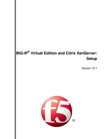
Creating the GTM Data Center The next task is to create a new GTM Data Center that corresponds to your physical data center. To create the data center 1. On the Main tab, expand Global Trafficand then click Data Centers. 2. Click the Createbutton. The New Data Center screen opens. 3. In the Namebox, type a name for this data center.