Transcription
Exterior Brick Masonry Veneersupported by Metal Plate Connected Wood TrussesSRR No. 1605-04Structural Building Components Association (SBCA)July 19, 2016Revised October 28, 2016SBCA is an APPROVED SOURCEThis research report is based on practical scientific research (literature review, testing, analysis, etc.), with the goal of supporting strategic needs forcode and standards development and market expansion. This research report complies with the following sections of the building code: IBC Section 104.11.1 and Section 1703.4.2 – "Research reports. Supporting data, where necessary to assist in the approval of materials orassemblies not specifically provided for in this code, shall consist of valid research reports from approved sources." IBC Section 202 – "APPROVED SOURCE. An independent person, firm or corporation, approved by the building official, who is competent andexperienced in the application of engineering principles to materials, methods or systems analyses."Copyright 2016Structural Building Components Association (SBCA) 6300 Enterprise Lane, Madison, WI 53719 608-274-4849 sbcindustry.com
Table of ContentsIntroduction: . 3Issue: . 3Background: . 3IRC requirements and limitations to MPCWT: . 6Analysis: . 6MPCWT Supporting Brick Veneer at Dormers: .12Conditions of Use: . 10References: . 14
SBCA Research ReportIntroduction:Wood frame structures with attached brick masonry veneer cladding are a common form of residential constructionthroughout the United States, particularly in central and southeastern regions with moderate seismic and/or high windactivity. Brick veneer cladding is appreciated for its pleasant appearance, excellent thermal performance and its ability toprevent water penetration.Residential brick veneer wall systems characteristically consist of brick masonry veneer at the exterior side of the wallwhich is attached to a wood frame wall. The wood framing and the brick veneer are connected with metal ties which holdthe brick veneer out from the wood framing, creating an air cavity between the brick veneer and the wood framing. Thecavity between the brick veneer and backup wood frame provides drainage, a thermal barrier and weather resistance.This is known as “simple rain screen” wall construction. No significant structural problems have been reported where brickveneer cladding was capable of supporting its own weight all the way down to the foundation, or where it was supportedby properly sized steel lintel angles and/or wood structural components at conventionally sized window and dooropenings. However, supporting brick veneer cladding above larger openings such as a two-car garage door or large bayand/or patio door represent more difficult conditions.In a typical brick veneer wall system, the wood framing is designed to carry all lateral and gravity loads, except forself-weight of the brick masonry. Nonetheless, brick veneer cladding does carry a portion of lateral load due to its higherstiffness than that of the wood backup structure. These lateral loads from exterior masonry walls are transferred throughthe tie connection, therefore the properties of these connections play a key role in the overall behavior and performance ofresidential brick veneer wall construction.Issue:The use of brick veneer supported by Metal Plate Connected Wood Trusses (MPCWT) is not covered by the prescriptivemethods of either the IBC or the IRC. Even so, code compliant use of MPCWT to support brick veneer can beaccomplished by both individual designs and by adhering to the recommendations that follow. This discussion mostlyfocuses on a common use of MPCWT’s; the gable end at the transition from a wider section of a building to a narrowersection. However, the concepts shown can be applied to many different situations utilizing MPCWT’s.Historically, considerable damage has been reported to residential brick veneer exterior cladding, including cracking,relative displacement, and the collapse of veneer brick masonry under out-of-plane loading resulting from strong windand/or moderate earthquakes. Although most of the reported failures were caused due to out-of-plane lateral loads,several failures including cracking and/or wall arching were reported to be caused by inadequate anchorage of the steellintels supporting the brick masonry, excessive deflections due to inadequate section of steel lintel, improper use ofveneer material, and poor workmanship specifically as it relates to installation of veneer ties.Key issues include: The out-of-plane wall damage occurs as brick veneer moves away from roof gable ends and walls resulting fromwind suction and/or seismic loading. This loading places a high demand on the displacement capacity of the ties. Tie fastener pull-out, failure of workers to embed ties into the mortar, poor bonding between ties and mortar, poorquality of mortar and tie corrosion. Improper installation of ties including placement above or below the mortar joints due to ties being installed beforethe brick laying process begin. When misaligned, the ties have to be bent up or down in order for ties to beembedded into the mortar joints. Misalignment not only reduces embedment depth but also reduces theeffectiveness of the ties because the wind direction is not acting parallel to the ties. Inadequate attachment of steel shelf angle to the roof gable end trusses and walls. Inadequately sized steel lintel.Background:Prescriptive installation requirements for supporting brick veneer with wood frame are specified in the 2009, 2012 & 2015International Residential Codes (IRC) with limitations. Supporting brick veneer can include steel angles bolted to wallframing or steel angles supported by beefed-up rafters. A movement joint is required to be installed between veneerssupported by foundation and veneers supported by wood or steel. Additionally, prescriptive installation requirements arespecified in The Masonry Society (TMS) 402/602, the Brick Industry Association (BIA) Technical Notes 18A, 28, 31B, and44B, and FEMA Technical Fact Sheet No. 5.4 Attachment of Brick Veneer in High-Wind RegionsSRR No. 1605-04Exterior Brick Masonry Veneer supportedby Metal Plate Connected Wood TrussesPage 3 of 15Copyright 2016
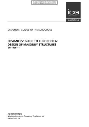
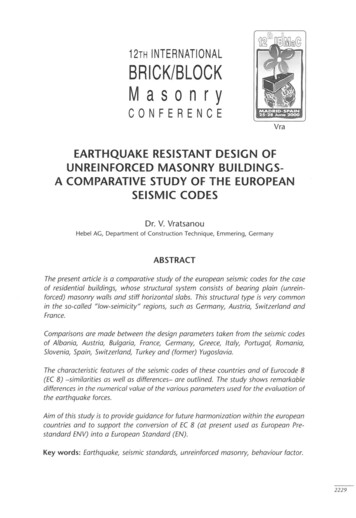
SBCA Research ReportAccording to the IRC brick veneer masonry can be supported by wood framing when observing the stated limitations:IRC 2015 R703.8.2 Exterior veneer support (IRC 2009 & 2012 R703.7.2)Except in Seismic Design Categories D0, D1 and D2, exterior masonry veneers having an installed weight of 40 pounds per square foot(195 kg/m2) or less shall be permitted to be supported on wood or cold-formed steel construction. Where masonry veneer supported bywood or cold-formed steel construction adjoins masonry veneer supported by the foundation, there shall be a movement joint betweenthe veneer supported by the wood or cold-formed steel construction and the veneer supported by the foundation. The wood or coldformed steel construction supporting the masonry veneer shall be designed to limit the deflection to 1/600 of the span for the supportingmembers. The design of the wood or cold-formed steel construction shall consider the weight of the veneer and any other loads.IRC 2015 R703.8.2.1 Support by steel angle (IRC 2009 & 2012 R703.7.2.1)A minimum 6-inch by 4-inch by 5/16-inch (152 mm by 102 mm by 8 mm) steel angle,with the long leg placed vertically, shall be anchored to double 2-inch by 4-inch (51mm by 102 mm) wood studs or double 350S162 cold-formed steel studs at amaximum on-center spacing of 16 inches (406 mm). Anchorage of the steel angleat every double stud spacing shall be not less than two 7/16-inch-diameter (11 mm)by 4-inch (102 mm) lag screws for wood construction or two 7/16-inch (11.1 mm)bolts with washers for cold-formed steel construction. The steel angle shall have aminimum clearance to underlying construction of 1/16 inch (1.6 mm). Not less thantwo-thirds the width of the masonry veneer thickness shall bear on the steel angle.Flashing and weep holes shall be located in the masonry veneer in accordance withFigure R703.8.2.1. The maximum height of masonry veneer above the steel anglesupport shall be 12 feet 8 inches (3861 mm). The airspace separating the masonryveneer from the wood backing shall be in accordance with Sections R703.8.4 andR703.8.4.2. The method of support for the masonry veneer on wood constructionshall be constructed in accordance with Figure R703.8.2.1The maximum slope of the roof construction without stops shall be 7:12. Roofconstruction with slopes greater than 7:12 but not more than 12:12 shall have stopsof a minimum 3-inch by 3-inch by 1/4-inch (76 mm by 76 mm by 6.4 mm) steel platewelded to the angle at 24 inches (610 mm) on center along the angle or as approvedby the building official.IRC 2015 R703.8.2.2 Support by roof construction (IRC 2009 & 2012 R703.7.2.2)A steel angle shall be placed directly on top of the roof construction. The roofsupporting construction for the steel angle shall consist of not fewer than three 2inch by 6-inch (51mm by 152 mm) wood members for wood construction or three550S162 cold-formed steel members for cold formed steel light frame construction.A wood member abutting the vertical wall stud construction shall be anchored withnot fewer than three 5/8-inch (15.9 mm) diameter by 5-inch (127 mm) lag screws toevery wood stud spacing. Each additional wood roof member shall be anchored bythe use of two 10d nails at every wood stud spacing. A cold-formed steel memberabutting the vertical wall stud shall be anchored with not fewer than nine No. 8screws to every cold-formed steel stud. Each additional cold-formed steel roofmember shall be anchored to the adjoining roof member using two No. 8 screws atevery stud spacing. Not less than two-thirds the width of the masonry veneerthickness shall bear on the steel angle. Flashing and weep holes shall be located inthe masonry veneer wythe in accordance with Figure R703.8.2.2. The maximumheight of the masonry veneer above the steel angle support shall be 12 feet 8 inches(38.61 mm). The airspace separating the masonry veneer from the wood backingshall be in accordance with Sections R703.8.4 and R703.8.4.2. The support for themasonry veneer shall be constructed in accordance with Figure R703.8.2.2.The maximum slope of the roof construction without stops shall be 7:12. Roofconstruction with slopes greater than 7:12 but not more than 12:12 shall have stopsof a minimum 3-inch by 3-inch by 1/4-inch (76 mm by 76 mm by 6.4 mm) steel platewelded to the angle at 24 inches (610 mm) on center along the angle or as approved by the building official.SRR No. 1605-04Exterior Brick Masonry Veneer supportedby Metal Plate Connected Wood TrussesPage 4 of 15Copyright 2016
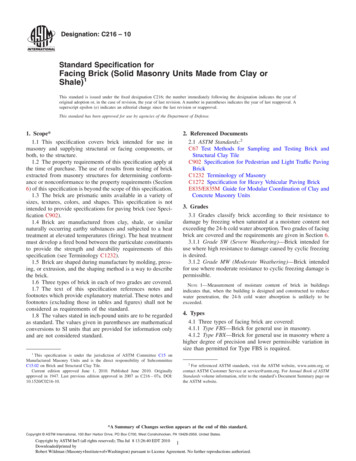
SBCA Research ReportIRC 2015 Veneer tiesR703.8.4 Anchorage. Masonry veneer shall be anchored to the supporting wall studs with corrosion-resistant metal ties embedded inmortar or grout and extending into the veneer a minimum of 1-1/2 inches (38 mm), with not less than 5/8-inch (15.9 mm) mortar orgrout cover to outside face. Masonry veneer shall conform to Table R703.8.4.R703.8.4.1 Size and spacing. Veneer ties, if strand wire, shall be not less in thickness than No. 9 U.S. gage [(0.148 inch) (4 mm)]wire and shall have a hook embedded in the mortar joint, or if sheet metal, shall be not less than No. 22 U.S. gage by [(0.0299 inch)(0.76 mm)] 7/8 inch (22 mm) corrugated. Each tie shall support not more than 2.67 square feet (0.25 m 2) of wall area and shall bespaced not more than 32 inches (813 mm) on center horizontally and 24 inches (610 mm) on center vertically.Exception: In Seismic Design Category D0, D1 or D2 or townhouses in Seismic Design Category C or in wind areas of more than30 pounds per square foot pressure (1.44 kPa), each tie shall support not more than 2 square feet (0.19 m2) of wall area.R703.8.4.1.1 Veneer ties around wall openings. Additional metal ties shall be provided around wall openings greater than 16 inches(406 mm) in either dimension. Metal ties around the perimeter of openings shall be spaced not more than 3 feet (914 mm) on centerand placed within 12 inches (305 mm) of the wall opening.Figure 1. Supporting brick veneer with MPCWTSRR No. 1605-04Exterior Brick Masonry Veneer supportedby Metal Plate Connected Wood TrussesPage 5 of 15Copyright 2016
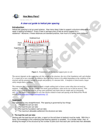
SBCA Research ReportIRC requirements and limitations to MPCWT:The IRC provides two details for attaching a steel angle to wood framing (Figure R703.8.2.1 and R703.8.2.2). In bothdetails, there is an adjacent wood framed backup wall. The IRC does not address MPCWTs supporting brick veneermasonry at all. Examples of supporting brick veneer with MPCWT utilizing a steel lintel are given in Figure 1.For buildings with conventional construction that contain structural elements exceeding the limits in IRC Section R301Design Criteria or otherwise not conforming to this code, the IRC has provisions regarding designing these elements inaccordance with accepted engineering practice.R301.1.3. Engineered designWhere a building of otherwise conventional construction contains structural elements exceeding the limits of Section R301 orotherwise not conforming to this code, these elements shall be designed in accordance with accepted engineering practice. Theextent of such design need only demonstrate compliance of nonconventional elements with other applicable provisions and shall becompatible with the performance of the conventional framed system. Engineered design in accordance with the International BuildingCode is permitted for buildings and structures, and parts thereof, included in the scope of this code.Furthermore, similar conceptual provision for structural components and/or assembly exceeding the limitation ofconventional construction is addressed in Section 2308.1.1 of the 2009, 2012 & 2015 International Building Code (IBC).2308.1.1 Portions exceeding limitations of conventional light-frame constructionWhen portions of a building of otherwise conventional light-frame construction exceed the limits of Section 2308.2, those portions andthe supporting load path shall be designed in accordance with accepted engineering practice and the provisions of this code. For thepurposes of this section, the term “portions” shall mean parts of buildings containing volume and area such as a room or a series ofrooms. The extent of such design need only demonstrate compliance of the nonconventional light-framed elements with otherapplicable provisions of this code and shall be compatible with the performance of the conventional light-framed system.Analysis:For the MPCWT carrying the brick/masonry wall, the following guidance and recommendations are provided based on2009, 2012 & 2015 IRC and IBC sections described above, wind loads specified in ASCE 7-10 “Design Loads forBuildings and Other Structures,” fastener strengths specified in the American Forest and Paper Association’s (AF&PA’s)National Design Specification for Wood Construction, Masonry Structures standards contained in TMS 402/602, generalguidance given in Brick Industry Association’s Technical Notes 18A, 28, 28B, 31B and 44B , FEMA Technical Fact SheetNo. 5.4 Attachment of Brick Veneer in High-Wind Regions and our professional judgment. The MPCWT must be designed for the additional loading from the brick in locations where there is not bearingdirectly below the brick. If the angle iron is being supported by bolts attached directly to the MPCWT, then the MPCWT must be designedwith the holes for the bolts taken into account. Truss total load deflection is limited to L/600. Load Duration factor for the brick veneer is CD 0.9. Creep factor for long-term deflection calculation shall be 1.5 for dry lumber and 2.0 for unseasoned lumber. Creepis defined as time-dependent deformation of a structural member under constant load. In this case brick deadload is a constant and/or sustained load (see ANSI/TPI 1-2014). Maximum weight of brick masonry veneer is 40 psf. Maximum height of brick masonry is 12’8” per the IRC. Sheathing must be covered with a water-resistant membrane, unless the sheathing is water resistant and thejoints are sealed. Attachment of steel lintel to MPCWT should be based on the recommended details per Figures 2 & 3. A minimum6 inches x 4 inches x 5/16 inch (152 mm x 102 mm x 8 mm) steel angle, with the long leg placed vertically, shallbe anchored to MPCWT using bolts installed per recommendations in Tables 1 or 2.The maximum slope of the roof construction without stops welded to the steel angle shall be 7:12. Supporting thebrick veneer with trusses with slopes greater than 7:12 but not more than 12:12 shall have stops, with a minimumsize of 3 inch x 3 inch x ¼ inch (76 mm x76 mm x 6 mm) steel plates, welded to the angle at a maximum spacingof 24 inches (610 mm) on center along the angle or as approved by the building official.SRR No. 1605-04Exterior Brick Masonry Veneer supportedby Metal Plate Connected Wood TrussesPage 6 of 15Copyright 2016
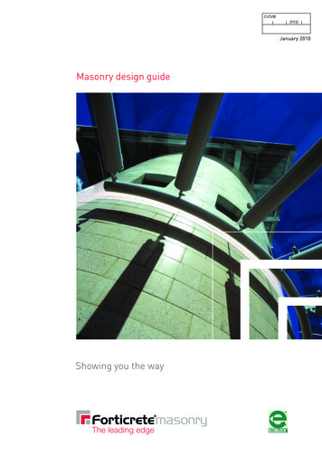
SBCA Research Report The lateral support of brick veneer carried with MPCWT is provided by the ties and backing system, includinglateral restraint of the trusses to resist the transferred loads. The ties must be capable of resisting tension andcompression resulting from forces acting perpendicular to truss plane. Stainless steel ties specified under ASTMA 240 or A 580 or corrosion protected ties such as zinc coated corrugated steel ties, minimum 22 U.S. gaugethick (0.0299”) by 7/8-inch wide and 6-inch long (0.76mm x 22 mm x 152 mm) complying with ASTM A 653 and A153 class B2 shall be used. Veneer ties shall be spaced at maximum 32” o.c. (813 mm) horizontally and 24” o.c.(610 mm) vertically and shall support no more than 2.67 ft2 (0.25 m2) of brick veneer wall area; however, it issuggested that for newer construction wall studs be spaced at 16” o.c., so that ties can be anchored at thisspacing. Strand wire ties are less susceptible to corrosion than corrugated steel sheet ties. Minimum strand wiresize diameter shall be 9 U.S. gauge [(0.148”) (4 mm)] and be spaced same as corrugated steel ties and shallhave a hook embedded in the mortar joint.Tables 4 & 5 provide recommendations for maximum vertical tie spacing for high wind areas when structuralgable truss vertical members or studs in a wall are spaced at 24”, 16” and 12” on center. In the areas that aresusceptible to both high wind and seismic loads, the masonry brick veneer system should be evaluated by aRegistered Design Professional to ensure that brick veneer cladding can resist both seismic and wind designloads. Design of the Lateral Restraint/Bracing of the truss is the responsibility of the building designer (see ANSI/TPI 12014). Reference the Architect’s/Design Engineer’s details and BCSI for additional gable end/truss bracingdetails. Flashing and weep holes shall be located in the brick veneer wythe above the steel angle per the building codes.Flashing should consist of normal base flashing, step flashing and counter flashing installed directly on theadjacent (i.e., lower) roof sheathing. Weep holes shall be at a maximum spacing of 33” (838 mm) o.c. and shallbe not less than 3/16” (5 mm) in diameter. Create vertical expansion joints at a maximum spacing of 25’ (7.6 m). The actual location of vertical expansionjoints in a structure depends on the structural configuration as well as the expected amount of horizontalmovement. The expansion joint in residential construction is typically sized to be similar in width to a mortar joint,usually between 3/8” (10 mm) and ½” (13 mm). In addition, vertical expansion joints should be considered at ornear corners, offsets and setbacks, wall intersections, changes in the wall height, where wall backing systemchanges, where support of brick veneer changes and where wall function or climatic exposure changes. (SeeFigure 6).Figure 2. Recommended detail for attaching steel lintel to MPCWT supporting brick masonry veneerSRR No. 1605-04Exterior Brick Masonry Veneer supportedby Metal Plate Connected Wood TrussesPage 7 of 15Copyright 2016
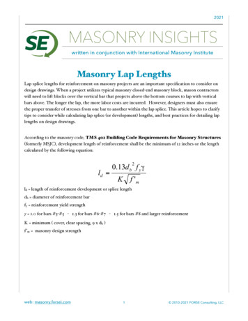
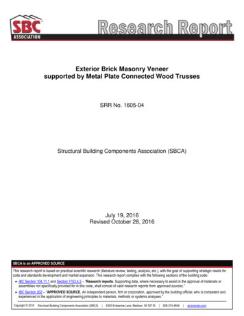
SBCA Research ReportFigure 3. Recommended detail for attaching steel lintel to MPCWT supporting brick masonry veneer with the use of bolts see Tables 1 & 2Bolt Spacing(Truss Vertical Member Spacing)24 inches o.c.c16 inches o.c.c12 inches o.c.c3/8-inch bolt diam.Max. 4’-6”brick heightMax. 6’-11”brick heightMax. 9’-4”brick heightBolt Diameter 1,bWith Structural Sheathing (OSB, Plywood)1/2-inch bolt diam.5/8-inch bolt diam.Max. 6’-1”Max. 7’-9”brick heightbrick heightMax. 9’-5”Max. 11’-10”brick heightbrick heightMax. 12’-8”Max. 15’-11” abrick heightbrick height3/4-inch bolt diam. 2Max. 9’-5”brick heightMax. 14’-3” abrick heightMax. 19’-2” abrick heightBolt shear capacity is calculated based on 2015 NDS for Wood Construction for lumber with Specific Gravity G 0.42 (Spruce-Pine-Fir) with moisture content less than 19% and thefollowing adjustment factors: CD 0.9, Ct and CM 1.0.2 Use only with minimum 2x4 vertical truss members. Fem 4700 psi, Fes 87000 psi, 5/16” Steel, no gap, Bolt Fyb 45000 psiBrick weight up to 40 PSF.a The maximum height of brick masonry veneer above the steel angle support using prescriptive requirements of 2015 IRC shall be 12’-8”. Weight of brick shall be included in trussdesign.b Pre-drill oval holes in the shelf angle for easier field installation adjustment.cIt must be noted that the design of the truss only accounts for the gravitational loads in the plane of the truss. The building designer needs to adequately account for loads normal to theface of the truss and the bracing/restraint of the roof and wall system.1Table 1: Shelf angle bolt sizing based on the supported height of brick masonry and truss vertical member spacing withstructural sheathing attached to the truss.SRR No. 1605-04Exterior Brick Masonry Veneer supportedby Metal Plate Connected Wood TrussesPage 8 of 15Copyright 2016
SBCA Research ReportBolt Spacing(Truss Vertical Member Spacing)24 inches o.c.c16 inches o.c.c12 inches o.c.cBolt Diameter1,bWith up to ½” of Non-Structural Sheathing (Weather Resistant Barrier, Insulation, etc.)3/8-inch bolt diam.1/2-inch bolt diam.5/8-inch bolt diam.3/4-inch bolt diam. 2Max. 3’-1”Max. 4’-4”Max. 5’-6”Max. 6’-8”brick heightbrick heightbrick heightbrick heightMax. 4’-9”Max. 6’-8”Max. 8’-5”Max. 10’-3”brick heightbrick heightbrick heightbrick heightMax. 6’-6”Max. 9’-0”Max. 11’-5”Max. 13’-9” abrick heightbrick heightbrick heightbrick heightBolt shear capacity is calculated based on 2015 NDS for Wood Construction for lumber with Specific Gravity G 0.42 (Spruce-Pine-Fir) with moisture content less than 19% and thefollowing adjustment factors: CD 0.9, Ct and CM 1.0.2 Use only with minimum 2x4 vertical truss members. Fem 4700 psi, Fes 87000 psi, 5/16” Steel with ½” gap between steel and truss, Bolt Fyb 45000 psi, Brick weight up to 40 PSF.a The maximum height of brick masonry veneer above the steel angle support using prescriptive requirements of 2015 IRC shall be 12’-8”. Weight of brick shall be included in trussdesign.b Pre-drill oval holes in the shelf angle for easier field installation adjustment.cIt must be noted that the design of the truss only accounts for the gravitational loads in the plane of the truss. The building designer needs to adequately account for loads normal to theface of the truss and the bracing/restraint of the roof and wall system.1Table 2: Shelf angle bolt sizing based on the supported height of brick masonry and truss vertical member spacing withnon-structural sheathing attached to the truss.Figure 4 Detail for attaching (3) Minimum 2x6’s to MPCWT supporting brick masonry veneer, directly above the 2x6’s,using shelf tapping wood screws, see Table 3SRR No. 1605-04Exterior Brick Masonry Veneer supportedby Metal Plate Connected Wood TrussesPage 9 of 15Copyright 2016
SBCA Research Report2 Staggered Rows of Screws @ 8” o.c.b,c2 Staggered Rows of Screws @ 12” o.c.b,c2 Staggered Rows of Screws @ 16” o.c.b,c2 Staggered Rows of Screws @ 24” o.c.b,cFasten Master TLOK08/LOG008 or Simpson SDS25800 or USP WS8 Screws 18” minimum screw lengthSP/DFL SG 0.50HF/SPF SG 0.42Max. 15’-3” aMax. 12’-11” abrick heightbrick heightMax. 10’-1”Max. 8’-6”brick heightbrick heightMax. 7’-6”Max. 6’-4”brick heightbrick heightMax. 4’-11”Max. 4’-1”brick heightbrick heightScrew shear capacity is calculated based on 2015 NDS for Wood Construction for lumber with Specific Gravity G 0.42 (Spruce-Pine-Fir) and Specific Gravity G 0.50 (Douglas FirLarch) with moisture content less than 19% and the following adjustment factors: CD 0.9, Ct and CM 1.0. 3” main member, 4-1/2” side memberUse only with minimum 2x6 members.a The maximum height of brick masonry veneer above the steel angle support using prescriptive requirements of 2015 IRC shall be 12’-8”.b Screws to be staggered half the o.c. spacing with a minimum 1-3/4” edge distance and 6” end distance. Weight of brick shall be included in truss design.cIt must be noted that the design of the truss only accounts for the gravitational loads in the plane of the truss. The building designer needs to adequately account for loads normal to theface of the truss and the bracing/restraint of the roof and wall system.1Table 3: Maximum height of brick masonry based on shelf tapping wood screw spacingFigure 5. Recommended detail for masonry brick veneer corrugated steel tie embedment, See Tables 4 & 5SRR No. 1605-04Exterior Brick Masonry Veneer supportedby Metal Plate Connected Wood TrussesPage 10 of 15Copyright 2016
SBCA Research ReportMaximum Vertical spacing for Ties in inches1,2,3,4,8Wind1,2,9Wind Speed(3-sec Peak Gust) Pressure (psf)115 mph120 mph130 mph140 mph150 mph160 mph180 mph19.120.824.428.332.537.046.88d (0.131” x 2.5”) Ring-Shank NailsWith Non-Structural Sheathing (Weather Resistant Barrier, Insulation, etc.) and 1-1/2” of Nail penetration in truss member.Truss members @ 24” o.c.SPFSYP1516514165121651016591268126NA7NA7Truss members @ 16” o.c.SPFSYP232452124518245152451318612186916Truss members @ 12” e vertical tie spacing is based on wind loads derived from ASCE 7-10 Components and Cladding – Method 1 (simplified – Figure 30.5-1, Zone 5, Effective wind area 10 sf), locatedin Exposure category B, h 30 ft., importance factor (I 1) and no topographic influence (Kzt 1.0). For other heights, exposure, importance factor and topographic influence, anengineered design is recommended. Table based on a tie in every vertical.2 Net Design Wind Pressures from ASCE 7-10 Figure 30.5-1 have been multiplied by 0.6 for Allowable Stress Design.3 Nail withdrawal strength is for truss lumber with Specific Gravity G 0.42 (Spruce-Pine-Fir (SPF)) and G 0.55 (Southern Yellow Pine (SYP)) with moisture content less than 19% andthe following adjustment factors: CD 1.0, Ct 0.8, CM, Ceg, and Ctn 1.0. See FEMA Technical Fact Sheet No. 5.4 Attachment of Brick Veneer in High-Wind Regions.W 1800G2D x 1.6 SPF NV 49.9 SYP NV 85.64 Nail embedment depth of 1-1/2” was assumed for 8d common ring-shank nails (0.131”-diameter x 2 ½”-long).5 The maximum vertical spacing allowed by the Brick Industry Association’s Technical Notes 28 is 24” & requires an anchor for every 2.67 sq. ft. of wall area.6 Where the wind pressure exceeds 30 psf, reduce wall area supported by each anchor to max. 2 SF per the IRC R703.8.4.1 & the Brick Industry Association’s Technical Note 287 Where wind pressure exceeds 40 psf do not space anchors more than 18” vertically & horizontally per the Brick Industry Association’s Technical Note 288 Additional anchors required around openings larger than 16” in either dimension. See the IRC or IBC for these requirements.9It must be noted that the design of the truss only accounts for the gravitational loads in the plane of the truss. The building designer needs to adequately account for loads normal to theface of the truss and the bracing/restraint of the roof and wall system.1Table 4: Suggested Maximum vertical spacing for brick veneer ties for truss members spaced at 24”, 16” and 12” centersWith non-structural sheathing attached to the MPCWTMaximum Vertical spacing for Ties in inches1,2,3,4,8Wind SpeedWind1,2,9(3-sec Peak Gust) Pressure (psf)115 mph120 mph130 mph140 mph150 mph160 mph180 mph19.120.824.428.332.537.046.88d (0.131” x 2.5”) Ring-Shank NailsWith ½” Structural Sheathing (OSB, or Plywood) and 2” of Nail penetration4Truss members @ 24” uss members @ 16” o.c.SPFSYP52424524524552424521245181861618612186, 7Truss members @ 12” The vertical tie spacing is based on wind loads derived from ASCE 7-10 Components and Cladding – Method 1 (simplified – Figure 30.5-1, Zone 5, Effective wind area 10 sf), locatedin Exposure category B, h 30 ft., importance factor (I 1) and no topographic influence (Kzt 1.0). For other heights, exposure, importance factor and topographic influence,
The design of the wood or cold-formed steel construction shall consider the weight of the veneer and any other loads. IRC 2015 R703.8.2.1 Support by steel angle (IRC 2009 & 2012 R703.7.2.1) A minimum 6-inch by 4-inch by 5/16-inch (152 mm by 102 mm by 8 mm) steel angle,