Transcription
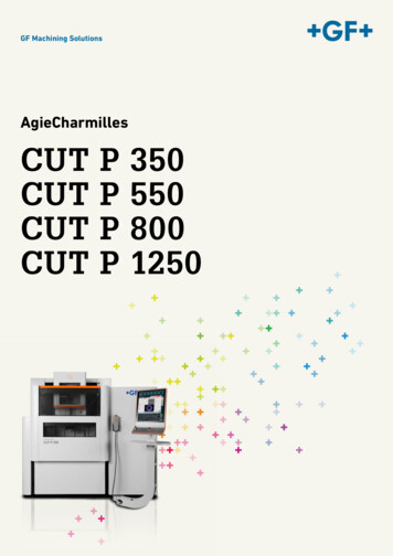
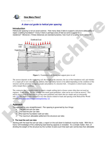
How Many Piers?By Gary Collins, P.E.eA clear-cut guide to helical pier spacingIntroductionArchivHelical pier spacing is not an exact science. How many does it take to support a structure adequately orrepair a settling foundation? Every 5 feet or perhaps every 8 feet as some suggest for aresidence? Moreover, if these distances are standard practice, how much of a safety factor is there?Figure 1. Foundation wall (beam) and support piers in soilWThe answer depends on the supporting soil, the weight of the structure, the size of the foundation wall, and whetherit’s a repair job or new structure. In addition, there are safety factors to be added depending on the condition of thestructure and the potential damage to people and property if a structure fails. A hospital or school needs a largersafety margin than a residence.PThe contractor that is installing piers to repair a simple settling deck or house corner often does not need anengineer. Codes differ. For the installer who needs good guidelines, what can he use to find an answer? Thisarticle aims to help fill that need by giving some guidelines and charts that are simple and yet structurallysafe. [1] The reader is also referred to very fine articles related to loads and spacing at the Helical Pier Worldwebsite:www.helicalpierworld.com/engineering. [2]ApproachHThe approach is very straightforward. Pier spacing is governed by four things: The load the soil can take The load the pier can take The load the foundation wall can take. The maximum allowable settlement the structure can take.1. The load the soil can takeStarting with the load the soil can take, a report on the soil down to bedrock must be made. With this inhand, full knowledge of the underlying load bearing capacity is revealed. It’s a simple matter, then, ofdividing the weight of the structure by the number of piers such that each pier carries less than allowable
load on the soil. For this article’s examples, load bearing values given by the following table will beassumed.Table 1. Presumptive load-bearing values of foundation materials[3]Load-bearing pressure(pounds per square foot)12,000eClass of materialCrystalline bedrock4,000ArchivSedimentary and foliated rockSandy gravel and/or gravel (GW and GP)3,000Sand, silty sand, clayey sand, silty gravel and clayey gravel(SW, SP, SM, SC, GM and GC)Clay, sandy clay, silty clay, clayey silt, silt and sandy silt (CI, ML,MH and CH)2,0001,500Using the crystalline bedrock value of 12,000 psf bearing capacity, three structural examples will be used:a one, two, and three story structure which could be a residence, a condo, or an apartment. The size willbe 60 ft x 40 ft for a total of 2400 sq ft. per floor. Assume brick veneer and a 9 ft high foundation wall 8inches thick and 9 ft high.The single story structureThe weight on the piers is the total weight of the structuredivided by the number of piers.For total load assume:PW - Roof snow load of 40 psf snow load (code in BoulderCO), - 10 psf roof structure and 40 psf first floor [4]- Brick veneer 9’ high is 315 lbs/lineal ft.HThe house load per square foot is the snow load roof structure first floor structure 40 10 40 90psf.The total house load will therefore be 90 lb/sq ft x 2400 sq ft 216,000 lbs. This will be divided ¾ on theouter foundation and ¼ on inner supports. Doing the math, the load of the house bearing on thefoundation 810 lbs/lineal ft.The above are the loads without brick veneer or the load of the concrete foundation walls. Add to this 315 lbs/linealft of brick veneer and 900 lb/lineal ft of concrete[5] foundation wall. Then brick foundation house 2025
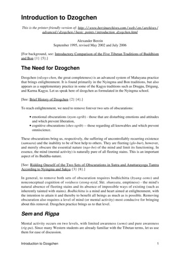
lbs/lineal ft of supported by piers. For a 200 ft perimeter, the load 405,000 lbs. This must be divided among thepiers.eThe goal is to get the loading on each pier down below 12,000 psf/pier, the maximum the soil can carryaccording to Table 1. Assuming each pier has a bearing area of 1.6 sq ft (two helices of 12” diametereach), there must be a minimum of 405,000 lbs/12,000 psf divided by 1.6 ft2/pier, or 21 piers around theperimeter. For a safety factor of 2, there should be 42 piers.Archiv40 piers fit into an even spacing on the 60 ft side and the 40 ft side of 5 ft between piers. Each pier isloaded with 10,125 lbs over 1.6 sq ft of helix, or 6449 psf on the soil, giving a safety factor of 1.9.The two story structureThe difference compared to example 1 is that there is a second floor and twicethe height of brick veneer. To maintain a pier spacing of 5 ft, use two helices of12” diameter. After doing the mathematics, the load would be 13,500 lbs foreach pier. This gives a bearing load on the soil of 8600 psf, giving a safetyfactor of 1.4.The brick veneer is very heavy, weighing 315 lbs per lineal foot for eachadditional story. If the two stories of brick are removed from the load equation,the bearing load for each pier drops to 6600 psf, giving a safety factor of a littlemore than 1.8.The three story structureHPWThe brick veneer is much too heavy for the 3 story structure to be supported by two 12”dia pier helices with any reasonable spacing. Removing the brick from the load equationand maintaining a 5 ft spacing as above, the load on the soil is 7740 psf, giving a safetyfactor of 1.62. The Load the pier can takeTurning to the second item, the load the pier can take, the type of loading must be considered. Itis torque loading while the pier is being installed. It is axial compressive loadingonce the pier is installedand the load is put on it.
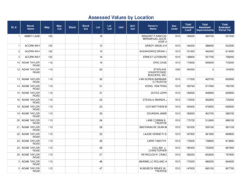
For torque, typical values for Colorado bentonite are 7000 ft-lbs for an 8”diameter helix. Calculations show that the resulting shear stress in thetorque tube is less than 9000 psi (allowable is 18,000 psi). This gives asafety factor of 2.ArchiveFor compressive loading, the above illustrations show this can range from10,000 to 15,000 lbs per pier. The resulting compressive stress is about15,900 psi (with an allowable stress in J55 alloy of 55,000 psi). Thisgives a safety factor over 3. If a larger factor is needed, simply increasethe wall thickness.Buckling due to compressive load or knotting due to torque is not aproblem since the soil usually provides adequate enclosure restraint forboth. If the intermediate soil is soft, sheathing with pull-down micropilesis a possibility.[6]3. The load the foundation can takeThe third consideration, the foundation load is the most complex to calculate but the least to matterbecause the loads prove to be insignificant. It is illustrated by Figure 1 and Figure 6, where thedistributed load together with fixed supports at the ends causes the beam to bend in the manner shown.Calculations show that the maximum bending stress is not in the middle; itis at each support and amounts to only 4 psi. Moreover, putting two rowsof rebar in the upper and lower sections of the foundation wall does notreduce the stress at all. This is because the concrete wall area is somassive compared to the small area of the #5 rebar (5/8” diameter) thatthe rebar contributes essentially nothing to the strength. It only holds theconcrete together when it cracks.W4. The settlement the structure can takeThis is specified by the structural engineer. It is usually in the order of ¼”(6 mm). This can be designed for and is dependent on the safety factor,that is, the ultimate load/design load that the pier can take. These methods are described in theDepartment of Transport’s publication FHWA-IF-99-02 on page 290.ConclusionPFrom the above, it is clear that of the four elements, soil load, pier load, the foundation load, and thestructural settling, the most important by far is the soil load. Pier spacing needs to be governed by that.HIf the pier column load and overstressing is of some concern, the safety factor can be increased by simplyincreasing the column wall thickness. As for the foundation load, it is not a concern because of the verysmall stresses.Table 2, Summary Table.Pier spacing in crystalline bedrock for various loads and pier geometries with the safety factor shown2-7/8” pier, one2-7/8” pier, one2-7/8” pier, twin2-7/8” pier, twin
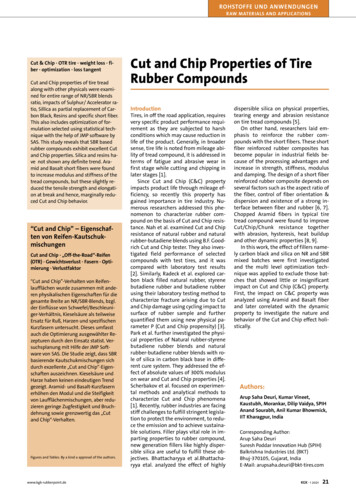
12” dia. helix8 ft, sf 1.45 ft, sf 1.85 ft, sf 1.6e10” dia. helix12” dia. helix10” dia. helixConventional light frame residential construction, no brickveneer1 story4 ft, sf 1.05 f sf 1.18 ft, sf 1.02 story3 ft, sf 1.04 ft, sf 1.15 ft, sf 1.33 story2 ft, sf 1.34 ft, sf 1.05 ft, sf 1.1Archiv4” brick veneer over light frame residential construction1 story3 ft, sf 1.14 ft, sf 1.25 ft, sf 1.35 ft , sf 1.92 story2.5 ft, sf 1.03 ft, sf 1.24 ft, sf 1.25 ft, sf 1.43 story2.0 ft sf 1.04 ft. sf 1.05 ft, sf 1.15 ft, sf 1.6As an example, if a builder was designing a 1 story house with brick veneer and wanted 5 ft betweenpiers, he should choose a 2 7/8” diameter pier with twin 10” diameter helices. The safety factor with thiswould be 1.3.Some engineers feel this table is too conservative and that the spacing istoo close. They point out that the IRC load bearing values (Table 1) areconservative to begin with. In addition, the load bearing calculationsmust include soil resistive friction on the shaft and an expanded bearingarea for the helix several diameters down, Figure 7. This all adds up to asafety factor of at least 3 over the numbers in Table 2. That is, one coulduse 3 times the spacing shown, or choose the spacing shown with asafety factor of 3 times greater.The above table can also be extended to include different pier geometriesand different soil conditions. It is meant only as a guide to help theestimator plan the job. If there are additional questions about it, anengineer should be consulted.WMr. Collins is a graduate of Stanford University with a BS and MS inmechanical engineering. He has extensive experience in all aspects ofmechanical design. The owner of Collins Consulting, Mr. Collins lives in Boulder CO. A registeredengineer in Colorado and California, he is available for consulting on helical pier applications. He may bereached at collins consulting007@msn.com. (303) 530-4106.HP[1] These are only guidelines for estimating the job. The contactor should consult a professional engineer if there isquestion about any aspect of loading, beam size, materials, or reinforcement.[2] Perko, Howard, Installation Torque as a Predictor of Helical Pier Axial Capacity. Also see Sieder, Gary, Whatan Engineer Needs to Know.[3] Table R401.4.1, 2003 International Residential Code, page 61[4] 2003 International Building Code, page 275[5] A density of 150/cu ft is used[6] See illustrations at websites t/transmission/TNN transmission/July01 7-9.pdf
outer foundation and ¼ on inner supports. Doing the math, the load of the house bearing on the foundation 810 lbs/lineal ft. The above are the loads without brick veneer or the load of the concrete foundation walls. Add to this 315 lbs/lineal ft of brick veneer and 900 lb/lineal ft of concrete[5] foundation wall.