Transcription
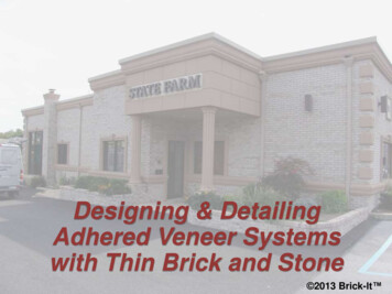
Designing & DetailingAdhered Veneer Systemswith Thin Brick and Stone11 2013 Brick-It
Copyright MaterialsThis presentation is protected by USand International Copyright laws.Reproduction, distribution, displayand use of the presentation withoutwritten permission of Brick-It isprohibited. 2013 Brick-It 22
AIA ProgramBRICK-IT is a Registered Provider with the AmericanInstitute of Architects Continuing Education Systems. Creditearned on completion of this program will be reported to CESRecords for AIA members. Certificates of Completion for nonAIA members are available on request.This program is registered with the AIA/CES for continuingprofessional education. As such, it does not include content thatmay be deemed or construed to be an approval or endorsement bythe AIA of any material of construction or any method or manner ofhandling, using, distributing, or dealing in any material or product.Questions related to specific materials, methods and services will beaddressed at the conclusion of this presentation.33
AIA-CES Program Credits1 credit earned on completion of thiscourse will be reported to AIA CESfor AIA members. Certificates ofCompletion for both AIA membersand non-AIA members are availableupon request.This course is registered with AIA CESfor continuing professionaleducation. As such, it does notinclude content that may be deemedor construed to be an approval orendorsement by the AIA of anymaterial of construction or anymethod or manner ofhandling, using, distributing, ordealing in any material or product.Questions related to specific materials, methods, andservices will be addressed at the conclusion of thispresentation.44
Brick It - Company Profile Thin BricksThin StoneMetal GridsAccessories55
CONTENTS1. Industry Codes & Standards2. Details and Design3. Installation Guidelines4. Specifications5. Project Gallery66
SECTION 177
Codes and Standards DefinitionsIBC 2012IRC 2102Local CodesMSJC 530ASTM C216ASTM C1088 Precast Stone AC51ASTM C15.11OthersICC EvaluationReports Manufacturer’sInstructions88
DefinitionAdhered VeneerIBC 2012, Chapter 2 – Definitions:Veneer secured and supportedthrough the adhesion of anapproved bonding material appliedto an approved backing.99
International Building Code – IBC 2012Chapter 14 – Exterior WallsSECTION 1401 GENERALSection 1401.1 Scope. The provisions of this chapter shall establish theminimum requirements for exterior walls; exterior wall coverings; exteriorwall openings; 1403.1 General. The provisions of this section shall apply to exteriorwalls, wall coverings and components thereof.Adhered veneers is classified as a wall covering inSection 1405.101010
2012 IBCChapter 14 – Exterior Walls1403.2 Weather protection.1. Exterior walls shall provide the building with a weatherresistant exterior wall envelope.2. The exterior wall envelope shall include flashing, asdescribed in Section 1405.4.3. The exterior wall envelope shall be designed andconstructed in such a manner as to prevent theaccumulation of water within the wall assembly byproviding a water-resistive barrier behind the exteriorveneer, as described in Section 1404.2,1111
2012 IBCChapter 14 – Exterior Walls1403.2 Weather protection.4. and a means for draining water that enters the assemblyto the exterior. Protection against condensation in theexterior wall assembly shall be provided in accordancewith Section 1405.3.Exceptions - Concrete & Masonry: See Chapter 19, 21 &MSJC – Code requirements still applicable- Testing- EIFS, see Chapter 1408.4.11212
2012 IBCSECTION 1404 – MATERIALS1404.2 Water-resistive barrier.1404.4 Masonry.A minimum of one layer of No.15asphalt felt, complying withASTM D 226 for Type 1 felt orother approved materials, shallbe attached to the studs orsheathing, with flashing asdescribed in Section 1405.4 insuch a manner as to provide acontinuous water-resistive barrierbehind the exterior wall veneer.Exterior walls of masonryconstruction shall be designedand constructed in accordancewith this section and Chapter 21.Masonry units, mortar and metalaccessories used in anchoredand adhered veneer shall meetthe physical requirements ofChapter 21. The backing ofanchored and adhered veneershall be of concrete, masonry,steel framing or wood framing.Comment: Consider high performancemembrane air/moisture/vapor barriers1313
2012 IBCSECTION 1405 – INSTALLATION OF WALL COVERINGS1405.10 Adhered masonryveneer. Adhered masonryveneer shall comply with theapplicable requirements inSection 1405.10 and Sections6.1 and 6.3 of TMS 402/ACI530 / ASCE 5.1405.10.1 Exterior adheredmasonry veneer. Exterioradhered masonry veneer shallbe installed in accordance withSection 1405.10 and inaccordance with themanufacturer’s instructions.1405.10.1.1 Water-resistivebarriers. Water-resistivebarriers shall be installed asrequired in Section 2510.6.(For wood based sheathing)1414
2012 IBCSECTION 1405 – INSTALLATION OF WALL COVERINGS1405.10.1.2 Flashing at foundation. A corrosion-resistant screedor flashing of a minimum 0.019-inch (0.48 mm) or 26 gaugegalvanized or plastic with a minimum vertical attachment flange of3½ inches (89 mm) shall be installed to extend a minimum of 1 inch(25 mm) below the foundation plate line on exterior stud walls inaccordance with Section 1405.4. The water-resistive barrier shall lapover the exterior of the attachment flange of the screed or flashing.1405.10.1.3 Clearances. On exterior stud walls, adhered masonryveneer shall be installed a minimum of 4 inches (102 mm) above theearth, or a minimum of 2 inches (51 mm) above paved areas, or aminimum of ½ inch (12 mm) above exterior walking surfaces whichare supported by the same foundation that supports the exterior wall.1515
2012 IBCCHAPTER 25 – GYPSUM BOARD AND PLASTERSECTION 2510 - LATHING AND FURRING FOR CEMENTPLASTER STUCCOSection 2510.6 Water-resistive barriers. Water-resistive barriers shall beinstalled as required in Section 1404.2 and, where applied over wood-basedsheathing, shall include a water-resistive vapor-permeable barrier with aperformance at least equivalent to two layers of Grade D paper. Theindividual layers shall be installed independently such that each layerprovides a separate continuous plane and any flashing (installed inaccordance with Section 1405.4) intended to drain to the water-resistivebarrier is directed between the layers.Exception: Where the water-resistive barrier that is applied over woodbased sheathing has a water resistance equal to or greater than that of 60minute Grade D paper and is separated from the stucco by an intervening,substantially nonwater-absorbing layer or drainage space.** Grade D paper is not asphalt felt.1616
IBC & IRC CodesIBC 1404.2 & IRC 702.3 Water Resistive Barrier (WRB)Steel Stud / Non-Wood Based Sheathing Minimum one-layer of no. 15 asphalt felt complying withASTM D 226 for Type 1 felt Industry / manufacturer recommendations Combination of 2 layers (similar to 2510.6) or An Air/Moisture/Vapor membrane (AMV) with equalproperties or A WRB or AMV with a drainage mat1717
IRC CodesInternational Residential CodeIRC – R 703Exterior Wall CoveringsIBC Similar Requirements1818
MSJC Adhered Veneer Codes6.1.3 – Design of Adhered Veneer1.2.3.4.5.6.7.Meet requirements of 6.1.6 andRational design of 6.2.1 orPrescriptive Section 6.3.26.1.6 - General Design RequirementsBacking to resist water penetrationWeeps and flashingAccommodate differential movement1919
Other Standards Brick: ASTM C216 / ASTM C1088 Mortar: ASTM C 270 (ProportionSpecification for Type N / PCL Mortar– Manufacturer / air-entrained - modified forThin Brick CMU / Concrete Brick: ASTM C-90 Stone: Varies2020
Manufacturer’s TestingDade County Florida Test2121
Adhesive Standards ASTM C297 / C297M - 04(2010) Standard Test Method for FlatwiseTensile Strength of Sandwich Constructions - Shear Strength ASTM C794 - 10 Standard Test Method for Adhesion-in-Peel ofElastomeric Joint Sealants - Standard pull test ASTM D3498 - 03(2011) - Standard Specification for Adhesives forField-Gluing Plywood to Lumber Framing for Floor Systems ASTM C557 - 03(2009)e1 - Standard Specification for Adhesives forFastening Gypsum Wallboard to Wood Framing APA 1984. AFG-01: Adhesives for Field-Gluing Plywood to WoodFraming. American Plywood Association - APA – The EngineeredWood Association2222
SECTION 22323
Adhered Veneer System Advantages Thin & lightweight is sustainableLess weight for structure – no shelf anglesExtended foundation not requiredThin wall system – more rentable/useable spaceSave costsSaves timeUses same brick (ASTM C216 / C1088)Many types, sizes, colors & materials2424
Metal Grid Systems Ledge provides support and alignmentSlots provide bonding of mortar and gridHoles allows adhesive to provide solid backingCreate equal weight distributionQuick, fast and less expensiveInstallation (except jointing) – year roundInterior & exterior applicationsAccepts many brick types and sizesResidential and commercial applications2525
System Components Metal Grid Support SystemsThin Brick or Thin StoneAdhesiveMortar JointsDrainage Mat (Option)Air/Moisture/Vapor BarrierWarrantiesAccessories2626
Designer Metal Grid PanelThin BrickMortar JointLinear slots provide bondingof mortar joint to metal gridExterior Sheathing / CMU /Concrete or other back-up systemAdhesive that seeps throughholes bridges any minor voidsbetween the panel and substrateprovides solid installation crucialto veneer longevity.Linear row of holes providesadditional mechanical bond betweenbrick and grid, and some substrateswhen adhesive installed.¼” metal ledge provides support forthin brick shelf and assures straightand level brick installation.Fasteners – 16” o.c. horizontally into studs atvery brick course – not less than 3 every 8”.Metal panels have amale and female endwhich provides aninterlockingconnection betweenpanels.Designer Metal Grid Panel8” High by 4’ & 8’ LongWater-Resistive Barrier (WRB)2727
Metal Grid ProfileMetal GridThin BrickMortar JointDrainage SlotsSystem OptionSupport /Alignment ShelfLinear MortarBonding SlotsAdhesive andholes2828
Drainage Metal Grid PanelThin BrickMortar JointLinear slots provide bondingof mortar joint to metal gridLinear row of holes providesadditional mechanical bond betweenbrick and grid, and some substrateswhen adhesive installed.Exterior Sheathing / CMU /Concrete or other back-up systemAdhesive that seeps throughholes bridges any minor voidsbetween the panel and substrateprovides solid installation crucialto veneer longevity.3/8” Drainage Weep Holes¼” metal ledge provides support forthin brick shelf and assures straightand level brick installation.Fasteners – 16” o.c. horizontally into studs atvery brick course – not less than 3 every 8”.Drainage Metal Grid PanelDrainage Mat with Fabric CoverWater-Resistive Barrier (WRB)2929
Detail at Drainage WeepsFabric prevents mortarfrom penetrating intodrainage slotOffset 3/8” drainageholes at shelf directwater into drainage matDrainage mat with fabriccover. Lap fabric permanufacturers instructionsSee Next Slide3030
Drainage SystemThin BrickMetal GridDrainage Mat3131
Drainage Hole at LapVertical section of”drainage holepermits water todrain into drainagemat.3232
Drainage Mat Detail3/16” Drainage ChannelFabric MeshDrainage mat with fabriccover. Lap fabric permanufacturers instructions.Fold fabric at base of walland at other terminationsfor insect screen option.3333
New Metal Panel Drainage System3434
New Metal Panel Drainage inageHolesMortarJointArea of adhesive about ½”wide by 8” or 4 sq. in perbrick.Adhesive at holes bridges any minorvoids between the panel andsubstrate provides solid installationcrucial to veneer 35longevity.35
DETAILSThere are many acceptable details at the base of walls, atwindows, doors, soffits and other locations. Each projectwill vary and the designer should always modify standarddetails to accommodate various window frames, curtainwall configurations and other design features.The following details are only a guide and are intended for useby professional architects and designers and should be modifiedto meet design and code requirements. Brick It disclaims all legalresponsibility for applying the information.3636
Wall Section Metal Grid & Drainage MatThin Brick Veneer UnitFastenersMetal Grid with Support LedgeMortar Joint & Grid LockAdhesive & LockDrainage MatDrainage Weep HolesStud WallInterior VaporPermeable Barrier ifrequired . Performcondensation analysisWRB / AMV BarrierExterior SheathingFlashingFlashing OptionsSee DetailsFoundation3737
Base of Wall - Flashing Option 1Thin BrickDrainage MatWRB / AMV BarrierExterior SheathingMetal Flashingwith Drip Edge –Min. 3 ½” with 1”cover overfoundationFoundation3838
Base of Wall - Flashing Option 2Thin BrickDrainage MatTermination Bar& SealantExterior SheathingWRB / AMV BarrierMetal Flashingwith Drip Edge –Min. 3 ½” with 1”cover overfoundationFoundation3939
Base of Wall - Flashing Option 3Thin BrickDrainage MatWRB / AMV BarrierExterior SheathingPre-formed weepscreed flashingFoundation4040
Window Head 1Thin BrickDrainage MatTermination Bar& SealantExterior SheathingWRB / AMV BarrierMetal Flashingwith Drip Edge4141
Window Head 2Thin BrickDrainage MatMembraneFlashingExterior SheathingWRB / AMV BarrierMetal Flashingwith Drip Edge4242
Window Head 3Thin BrickDrainage MatTermination Bar& SealantExterior SheathingWRB / AMV BarrierMetal Flashingwith Drip Edge4343
Window Sill DetailFlashing / TrimEnclosureWRB / AMV BarrierExterior SheathingDrainage MatThin Brick4444
Window Jamb 1Thin BrickDrainage MatExterior SheathingWRB / AMV BarrierTrim Enclosure4545
Window Jamb 2Thin BrickDrainage MatExterior SheathingWRB / AMV BarrierCorner Brick4646
Soffit / Top of WallBlockingAluminumTermination barand/or sealantMetal FlashingOptional SealantThin BrickDrainage MatWRB / AMV BarrierExterior SheathingFor informationonly – Architectto provide soffitdetails4747
Detail Continuous Insulation and Z GirtThin BrickAdhesiveFastenerDrainage Mat (Option)Metal PanelExterior SheathingWRB / AMV BarrierInsulationPrimary AMVExterior SheathingCondensation analysisrequired when combiningC.I. and insulation betweenstud space.R-8 BattInsulationContinuousvertical Z-Girtwith optionalthermal breakpadsPlan ViewCheck for compliance with NFPA 2854848
R- Value CalculationsASHRAE 90.1 (2007)for Zone 5Prescriptive Option 1Maximum U-Factor 0.064 R-15.634949
R-Value Calculation – 2” InsulationASHRAE 90.1 (2007) for Zone 5Maximum U-Factor 0.064 R-15.63Exceeds requirement by 38%With R-8 Batt InsulationCondensation analysis requiredwhen combining C.I. andinsulation between stud space.Outside Air FilmThin Brick Veneer *Air Space or DrainageAir Barrier5/8" Exterior Sheathing2” Rigid InsulationAir Barrier5/8" Exterior SheathingBatt Insulation1/2" Gypsum BoardInside FilmTotal 21.83U-Factor: 1/R .0455050
Dew Point with R-10ci & R-8Wall values entered for DOW Dew Point AnalysisSee next page for results5151
Dew Point with R-10ci & R-8Actual & Dew PointTemperatures do notcross - ok5252
BIA Modular Brick SizesSee Notes – next slide5353
BIA Modular Brick Sizes1.2.3.4.Some manufacturers may use a brick designation different from that shown.No brick designation is provided due to inadequate consensus amongmanufacturers.Common joint sizes used with length and width dimensions. Actual bed jointthicknesses vary based on vertical coursing and actual brick height.Specified dimensions may vary within this range from manufacturer to5454manufacturer.
BIA Non-Modular Brick SizesBrick Coursing and Joint Size for King / Queen - 5 Courses 16"#HTCoursesTotal Brick16" ModRemainJointsJoint Size1 2 9/16"x 5 courses12 13/16"less 16" 3 3/16"/ 5 joints 5/8" Joint2 2 5/8"x 5 courses13 1/8"less 16" 2 7/8"/ 5 joints 9/16" Joint3 2 11/16" x 5 courses13 7/16"less 16" 2 9/16"/ 5 joints 1/2" JointOK4 2 3/4"13 3/4"less 16" 2 1/4"/ 5 joints 7/16" JointOK14 1/16"less 16" 1 15/16" / 5 joints 3/8" Joint55OKx 5 courses5 2 13/16" x 5 coursesTo Big?55
King / Queen Joint Sizes#12345Brick Height2 9/16"2 5/8"2 11/16"2 3/4"2 13/16"Mortar Joint5/8" Joint9/16" Joint1/2" Joint7/16" Joint3/8" JointModular3 3/16"3 3/16"3 3/16"3 3/16"3 3/16"Custom panel are available to accommodatebrick heights and mortar joints5656
8” Modular Brick Coursing3 courses of brick 8”8” / 3 2 2/3” about 2 11/16” Brick plus jointGeneral Terms - Brick 2 ¼” 3/8” joint 2 5/8”Joint is actually 7/16” ( /-) 2 ¼” 2 11/16”3/8”-7/16”2 ¼ /- ”3/8”7 5/8”8”8”3/8”-7/16”2 ¼ /- ”3/8”-7/16”2 ¼ /- ”5757
Running Bond8”Running Bond - Modular Brick5858
Stack Bond8”Stack Bond - Modular Brick5959
Accent Patterns8” HighSoldier BrickHeaderCourseSailor Brick4” HighRowlockRunning Bond - Modular Brick6060
Common Bond8”Common Bond - Modular Brick6161
Flemish Bond8”Flemish - Modular Brick6262
Running Bond8”Running Bond - Econo Brick (4 x8)6363
Running Bond16”Running Bond – Jumbo Brick(5 Course 16”)6464
Running Bond8”Running Bond - Stylo Brick (8 x8)6565
Other Brick Sizes & Materials2 ½” x 8” Brick (California)2 ¼” x 12” Brick4” x 12” BrickStone VeneerCMU VeneerManufactured Veneers6666
Traditional Thin-Set BrickThin BrickMortar JointLathDrainage MatOption)Mortar Setting BedWRB / AMBBack-up WallSystem6767
Thin Brick Options Manufactured Stock Thin BrickSpecial Order BricksTumbled BricksCut Brick of any TypeClinker BrickGlazed Brick6868
Thin Brick Options6969
Corners and Specials7070
SECTION 37171
Important Notes The following installation instructions areguidelines. See detailed manufacturer’sinstallation instructions and specificationsfor complete installation requirements. Refer to relevant codes, industrystandards and project drawings andspecifications7272
Preparation Verify back-up is per project requirements– Plumb / level / openings / stud spacing Obtain written acceptance of the water resistive orair/moisture/vapor barrier and related flashings Install all flashings and transitions Obtain material certifications and submittalinformation for project compliance Provide samples and mock-up as required Obtain compatibility statement for adhesive andWRB/AMB, flashing and other adjacent materials7373
Water Resistive Barrier (WRB)Air / Moisture / Vapor Barrier (AMV) Many choices AMV membrane products are self healing atfasteners Permeable and non-permeable Thin paper / plastic products should have tapedjointsPaper / PlasticAdhesiveMembrane74 Spray74
Drainage Mat Installation3/16” Drainage ChannelFabric Meshfaces outsideLap fabricover lowerpanelWrap fabricat exposedends7575
Tools HammerHacksawMetal SnipsCircular SawBrick NipperWet SawCaulking GunDrillMortar BagJointing ToolsMortar MixerStaging7676
Safety Work in well ventilated areas Wear protective gloves, safety glasses,masks, hard hats and appropriate clothing Metal panels have sharp edges Follow all OSHA and job site safetyregulations7777
Metal Grid Panel Installation Install metal grid panels in running bondLeave a ¼” to 3/8” space between panelsInterlock panels in vertical applicationFasten at every stud (16”) o.c. horizontally and3 per 8” vertically. Engineering may be required. Use recommended fasteners only Install corners per details Clean metal grid of dust, dirt, oils, etc. prior tobrick installation7878
Corner Panel Installation7979
Fasteners Non-Corrosive (galvanized, coated, stainless steel)Spacing: 3 per 8” vertically and 16” o.c. horizontallySelf Drilling Wafer Head for steel studsFlat Head Power ActuatedRibbed NailsStaplesMasonry and concrete walls requirefasteners and adhesive8080
Fasteners8181
Adhesives Use and purchase adhesives from the manufacturer.These products have been tested and approved for usewith the system. Use of other products will void any and all warranties Apply adhesive beads in thickness and pattern shown Slide brick in a slightly side to side motion to spreadadhesive Do NOT use excessive amounts of adhesive Allow adhesive to dry at least 24 hours before mortarjointing8282
AdhesivesAdhesives currently used by Brick ITSonneborn (BASF) Premium Adhesive is apolyurethane based, moisture cure adhesive. Canbe installed in cold weather. Moisture cure meansmoisture will not affect bond. OK in heat.Titebond – Provantage Heavy Duty Adhesive is asolvent based adhesive.Can be installed in cold weather. Adhesive can meltin high heat installations before cure. Once cured,product is stable. Acceptable for interiors yearround. Less expensive.8383
Adhesive Option 1 – otsDrainageHolesMortarJointArea of adhesive about ½”wide by 8” or 4 sq. in perbrick.Adhesive at holes bridges any minorvoids between the panel andsubstrate provides solid installationcrucial to veneer 84longevity.84
Adhesive Option 2 – Drainage & geHolesMortarJointArea of adhesive about ½”wide by 8” or 4 sq. in perbrick.Adhesive at holes bridges any minorvoids between the panel andsubstrate provides solid installationcrucial to veneer 85longevity.85
Adhesive Option 3 – Drainage & geHolesMortarJointArea of adhesive about 1”Diameter (.8 si)”- 4 per brickor about 4 sq. in per brick.Adhesive at holes bridges any minorvoids between the panel andsubstrate provides solid installationcrucial to veneer 86longevity.86
Thin Brick Installation Layout brick to modular bond in advanceInstall corner brick to bond patternAdjust joints as required: 3/8” /- 1/8”Use plumb lines as required to keep verticaljoints in alignmentDo not install defective brickBlend brick that have a rangeDo not hammer cut brick – use a sawInstall expansion joints as shownApply adhesive per manufacturer’s87recommendations87
Mortar Joint Installation Allow adhesive to dry for a least 24 hours Use and purchase mortar from the manufacturer. Thesemortars have been tested and approved for use with thesystem. Use of other products will void any and all warranties Make sure panel is free of dirt, oil and adhesive Install mortar in joint with grout bag or by industryapproved method Fill joints but avoid over grouting on brick surface Fill horizontal first, then vertical for even setting time Tool joint when mortar is thumb print hard Tool vertical (head joints), then horizontal (bed joints) Tool joint concave using a concave jointer or dowel Clean excess when dry8888
Wash-down1. Use cleaning products as recommended by thebrick manufacturers2. Some brick contain iron, manganese or othersubstances that are sensitive to acids3. Wait 7 days (or longer - weather dependent) or asrecommended after mortar joint pointing4. Protect adjacent areas5. Dilute cleaners as much as possible and avoidstrong concentrations of acid6. Pre-Wet entire area thoroughly7. Rinse area with plenty of water8. Follow manufacturers instruction8989
Weather Conditions Install adhesive in temperatures asrecommended by manufacturer Do not install mortar joints if temperature isbelow 40 degrees. Provide heat and protection per codes Wet brick in advance (night before) prior tomortaring in hot weather or if height absorptive9090
Sheathing / Flashing9191
Water Resistive Barrier9292
Metal Grid Panel Installation9393
Thin Brick Installation9494
Thin Brick Installation9595
Thin Brick Installation9696
Quality Assurance9797
Quality Assurance9898
Education / Training & Installer Requirements Installer shall have received instructionsfrom the manufacturer and a Certificate ofTrained Applicator Installer must be experienced and trainedin brick masonry construction If requested, submit a list of recentlycompleted projects Request and pay for job site inspection ifrequired by project9999
Warranty Provide manufacturers standard 20 yearwarranty Request and pay for periodic job siteinspection if required by project to validatewarrantyStandard 20 Year Warranty100100
SECTION 4SEE MANUFCATURERS ANDARCHITECTS RECOMMENDEDSPECIFICATIONS101101
SECTION 5102102
SECTION 5103103
104Commercial104
105Commercial105
106Commercial106
107Commercial107
108Commercial108
109Commercial109
110Commercial110
111Interior111
112Commercial112
113Commercial113
114Residential114
115Commercial115
116Commercial116
117Commercial117
118Commercial118
119Commercial119
120Commercial120
121Commercial121
122Commercial122
123Commercial123
124Commercial124
125Residential125
126Residential126
127Residential127
128Residential128
129Residential129
130Interior130
131Interior131
132Interior132
133Interior133
AIA-CES ProgramThis concludes The American Institute ofArchitects Continuing Education Systems CourseRobert DolinskiBrick-It Company17 Central AveHauppauge, NY 11788Email: Robert@brickit.com631.591.9195 - Cell631-902-9331 Direct631-244-3993 x 312134134
Brick It - Company Profile Thin BricksThin StoneMetal GridsAccessories135135
Designing & DetailingAdhered Veneer Systemswith Thin Brick and Stone136136 2013 Brick-It
SECTION 1405 - INSTALLATION OF WALL COVERINGS 1405.10.1 Exterior adhered masonry veneer. Exterior adhered masonry veneer shall be installed in accordance with Section 1405.10 and in accordance with the manufacturer's instructions. 1405.10.1.1 Water-resistive barriers. Water-resistive barriers shall be installed as required in Section 2510.6.