Transcription
http://www.e-polymers.orgISSN 1618-7229e-Polymers 2004, no. 067.Molecular deformation mechanisms and mechanicalproperties of polymers simulated by molecular dynamicsRicardo Simões 1,2 *, António M. Cunha 1, Witold Brostow 21Department of Polymer Engineering, University of Minho, 4800-058 Guimarães,Portugal; Fax 351 253510339; rsimoes@dep.uminho.pt, amcunha@dep.uminho.pt2Laboratory of Advanced Polymers and Optimized Materials (LAPOM), University ofNorth Texas, Denton, TX 76203-5310, USA; brostow@unt.edu(Received: July 6, 2004; published: October 22, 2004)Abstract: Virtual polymeric materials were created and used in computer simulations to study their behavior under uniaxial loads. Both single-phase materials ofamorphous chains and two-phase polymer liquid crystals (PLCs) have beensimulated using the molecular dynamics method. This analysis enables a betterunderstanding of the molecular deformation mechanisms in these materials. It wasconfirmed that chain uncoiling and chain slippage occur concurrently in thematerials studied following predominantly a mechanism dependent on the spatialarrangement of the chains (such as their orientation). The presence of entanglements between chains constrains the mechanical response of the material. Thepresence of a rigid second phase dispersed in the flexible amorphous matrixinfluences the mechanical behavior and properties. The role of this phase in reinforcement is dependent on its concentration and spatial distribution. However, thisis achieved with the cost of increased material brittleness, as crack formation andpropagation is favored. Results of our simulations are visualized in five animations.1. IntroductionThe deformation mechanisms taking place at the macromolecular level are not yetfully understood. It is generally accepted that a number of different mechanismsoccur, depending on the structure of the material and the thermo-mechanicalconditions associated to the imposed load. Several models were proposed to explainthe specific mechanisms that allow the material to respond to an external load, suchas chain uncoiling, chain sliding, crack formation and propagation, and splitting oflamellae in semi-crystalline polymers. However, the conditions and requirements foreach mechanism to take place are far from established. To understand and to modelthose deformation mechanisms are fundamental steps for the prediction of themechanical properties of polymers.Computer simulations have been performed with the aim of, among other topics,providing insights into this problem. The present paper reports computational resultsfor simple polymer models under conditions that will enable the identification andstudy of some of the deformation mechanisms referred above.Both amorphous polymers and two-phase polymer liquid crystals (PLCs) have beeninvestigated. The latter represent relatively new and insufficiently explored materials.1
Unlike traditional purely flexible polymers, PLCs are typically copolymers consistingof rigid liquid crystalline (LC) sequences combined with flexible sequences [1]. Thus,in PLCs there is no lack of adhesion between the flexible constituent and the reinforcement – the main drawback of traditional heterogeneous composites [2,3]. Sincethe rigid LC constituent is not homogeneously dispersed throughout the material, it ispossible that certain spatial arrangements of the second phase within the PLCmaterial provide higher mechanical stability than others when the material issubjected to an applied load.When compared to other polymers, PLCs exhibit a series of improved properties[4-6]. Due to their complexity, they have been concomitantly studied by statisticalmechanics [7,8], viscoelastic models [9-11], and experimental methods [1,4-6].Previous and ongoing results from computer simulations of PLCs can provideinformation to complement these other approaches.As eloquently formulated by Fossey [12], simulations provide information not readilyaccessible experimentally, either due to the prohibitive nature of the tests, theinadequacy of existing equipment and techniques to study a particular phenomenon,or other impediments. Two very important advantages of computer simulations arethe ability to study extreme conditions that cannot be replicated in a controlledenvironment, and even more important, being able to study the effects of one systemvariable at a time. In the case of PLCs, an important advantage of computer simulations is the much lower cost compared to extensive laboratory experimentation withthese materials. Also, controlling their morphology – the dispersion of the LC phase –is possible but very difficult in experimental methods.Due to the large amount of data resulting from the simulations, it is of paramountimportance to develop adequate means to scavenge that information for pertinentresults and to represent those results. For this, it becomes essential to employ 3Dvisualization and animation techniques that enable real-time observation of thephenomena taking place in the molecular-level simulations.It is important to point out that these simulations are not performed with the intent ofreplacing experimental testing, but rather to complement it. The concomitant use ofcomputer simulations and experiments should produce a synergistic effect, eventually leading to a more complete understanding of the properties and behavior ofpolymeric materials.2. Applications of molecular dynamics to polymer behavior and propertiesA detailed review of the various computer simulation methods has been provided byFossey [12] and will not be covered here. However, some important research effortsconducted on computer simulations shall be briefly mentioned.In recent years, molecular dynamics (MD) simulations have been used to study awide variety of phenomena, in many different fields of work. Smith et al. [13] used MDto simulate the X-ray scattering pattern, while Gerde and Marder [14] investigatedfriction and its connection to the mechanism of self-healing cracks. Theodorou et al.have investigated the phenomena of diffusion [15], permeation [16], elongational flow[17], and stress relaxation [18]. However, they have performed their simulationsmostly at the atomistic level, following a different approach from the one employed inthe present study.2
Other relevant MD applications in materials science include the investigation of thethermodynamic properties of simple fluids and polymer melts [19,20], the meltingprocess, including that of thin layers on a substrate [21,22], and the transport of fluidsthrough a polymer membrane [23]. It is also of interest to mention the kinetic model offracture, used by Termonia and co-workers to simulate the mechanical behavior ofpolymers [24-26] and the simulation of spider silk fibers [27], and the use of fracturemechanics in the simulation of polymers [28-31].In earlier work, computer simulations have been used to study stress relaxation inmetals and polymers [32,33]. The presence of defects was found to increase the timespan for relaxation, this by several orders of magnitude. These simulations have alsoindicated that stress relaxation is mainly achieved by plastic deformation occurring inthe vicinity of defects. In an ideal lattice, the force required to initiate a crack ishigher, but then the force is sufficient to cause quick propagation. The stressrelaxation curves obtained in the simulations have all the essential features of experimental curves and are in accordance with the Kubát cooperative theory of stressrelaxation in materials.The tribological properties of polymeric materials have also been investigated;recently developed scratching simulations are providing information about whichstructures are most resistant to scratch [34]. These have shown that the localstructure affects scratch resistance and recovery, and that the preferential migrationof a rigid second phase to the surface of a two-phase material can improve itsperformance.The present paper follows previous work on the use of computer simulations to studymechanical properties [35] and crack formation and propagation in polymer liquidcrystals (PLCs) [36]. The key question is, obviously, where cracks form in thematerial and how they propagate. Cracks could have equally been expected to formin the flexible matrix because of its relative weakness or inside the second phasebecause of its relative rigidity. Simulations have shown that cracks preferentiallyappear between second phase agglomerates in close proximity and grow next to theinterface between the two phases. Cracks can then propagate through the flexiblephase, for example in order to connect to another crack.3. Simulation modelIn these simulations, the amorphous chains are represented using the statisticalsegment model, as advocated by Flory [37]. Here, each segment represents severalrepeating units of a polymeric chain. The creation of materials on the computer isdescribed in section 4.The segments interact according to a set of potentials that differ for intra-chainchemical bonding and inter-chain secondary interactions, the later being muchweaker. In order to study one- and two-phase systems, different potentials have alsobeen defined to represent the interactions between segments of the flexible polymermatrix and those of a rigid liquid-crystalline (LC) second phase. A narrow Morse-likepotential is used for the intra-chain bonds between rigid LC segments, whereas forthe intra-chain bonds between flexible segments a spliced double-well potential hasbeen incorporated. This double-well potential allows for conformation transitions as inreal polymer chains. The weaker inter-chain (secondary) van der Waals interactionsare represented by a Morse-like potential with a relatively broad well. A detaileddescription of the interaction potentials has been provided in ref. [35].3
The simulations have been performed using the molecular dynamics (MD) method,with the time evolution calculated through a leap-frog algorithm [38]. The preferenceover the Monte Carlo (MC) or Brownian dynamics methods has been previouslydiscussed [35,36]. The MD method was developed by Alder and Wainwright, with theinitial intent of studying the phase diagram of a system of hard spheres [39]. Later,continuous potentials have been introduced to provide a more accurate representation of the forces acting on each particle in the system. Soon after that, Rahmanimplemented Lennard-Jones potentials in his simulations [40], creating thefoundation for most of the work being currently done in this area.In the MD method, a system of N particles (statistical segments in this case) isconsidered, each of them characterized by three Cartesian coordinates and threemomentum components along the main axes. These variables are calculated at eachtime step of the simulation, effectively describing the time-dependent behavior ofevery segment in the system. In contrast to traditional MC in which one particlemoves at a time, here all particles are moved at once at each time step. Since time isan explicit variable in MD, the method can be used to simulate not only equilibriumproperties but also time-dependent ones. This is particularly important when dealingwith viscoelastic materials.The segments are disturbed from their initial lattice-based positions by a smallfraction of the average intersegmental distance before the simulation begins. Duringthe first stage of the simulation, the material is allowed to equilibrate for a fewthousands of time steps without any external forces applied. After a quasi-equilibriumstate has been reached, a uniaxial external tensile force is applied to the edges ofthe material along the x-axis and the state of the system is monitored and periodicallyrecorded. The value of the external force continuously increases until fracture isobserved.The employed MD simulation method assumes that the forces on particles are nearlyconstant over very short periods, which defines the time step for the simulation. It canbe shown that in the limit of short time steps, this procedure samples statesaccessible in the micro-canonical ensemble. However, additional features can beadded to the algorithm that allow one to specify the configurational temperature, orallow the simulation to access a range of energies and/or pressures that correspondto either the canonical or isothermal-isobaric ensembles.When using the micro-canonical ensemble, one maintains the number of particles,volume and energy (NVE) constant throughout the simulation. However, thesimulations reported in this paper were performed at constant temperature, to avoidan effect of stochastic thermal forces, since the purpose is to study non-thermalsources of polymer fracture [32]. Also, the material is allowed to deform freely alongall three axes. This implies that upon sufficient deformation, there is formation andpropagation of cracks, which contributes to an increase of the internal free volume.Thus, this procedure is closer to the isothermal ensemble. When performingconstant-temperature MD [38], one has to rescale the velocities at each time step,based on the kinetic energy of the system. Further details concerning the simulationmodel were provided in ref. [35] and in the Appendix.4. Material generation proceduresFor these simulations, both one- and two-phase polymeric materials were created onthe computer. In both cases, the matrix consists of amorphous chains with a4
molecular weight distribution. For the two-phase systems, a rigid liquid-crystalline(LC) phase is then dispersed in the flexible matrix. After the material is generated andbefore the simulation begins, columns of rigid segments are placed at the left andright edges of the material, in order to avoid chain pullout; see for example Animation2. The external force is applied to these segments and they transfer it to the bulkmaterial. These rigid edges can be considered the simulation equivalent of theopposing clamps in a tensile test apparatus.4.1. Two- and three-dimensional structures of amorphous chainsThe amorphous phase is created using an approach developed by Mom [41] andlater modified to suit specific needs [42]. Initially, all segments in the material arepositioned in equidistant lattice positions, each segment representing at this stageone chain of length 1. The triangular lattice has been chosen for several reasonsstated before [42]. Particularly, this lattice results in a more realistic coordinationnumber than, for example, the square lattice. This methodology is effective both forcompletely filled lattices and those containing vacancies.After the segments are placed, the system is searched for neighboring end-of-chainsegments. At the first stage, all segments fulfill this condition and, therefore, astatistical function determines which segments bond together forming chains oflength 2. The chains continue to grow by bonding of adjacent end-of-chain segmentsuntil no more segments can be bonded in this way. When a segment can equallybond to several others, the preferential direction of the bonding can be statisticallycontrolled in order to give rise to structures with varying degrees of orientation.However, in the present work only the two limiting cases were investigated:structures completely aligned with a specific direction and structures with nopreferential orientation. Although this is a simple procedure, the resulting computergenerated materials (CGMs) exhibit realistic features, such as a molecular weightdistribution and physical entanglements between chains [42].4.2. Second phase incorporation and distributionA rigid LC second phase can be added to the flexible matrix to mimic the structure ofpolymer liquid crystals (PLCs). In these materials, the LC phase has been experimentally found to form quasi-spherical agglomerates, often designed by islands [43].Islands are introduced in the CGMs by random sequential addition, until the desiredconcentration is achieved. The random placement of the islands sometimes resultsin regions of high local concentration, which was found to greatly affect crackinitiation and crack propagation [35]. The present paper addresses the influence ofthe LC phase concentration on the mechanical properties, as well as the behavior ofspecific spatial distributions of the islands. For the latter, hand-made CGMs havebeen created where the islands are placed at desired locations.A more detailed description of the entire one- and two-phase material generationprocedure, including a brief review of alternative methods to generate polymericmaterials on a computer, has been provided in ref. [42].5. Selected resultsIn section 5.1 results are described pertaining to a single-phase CGM containedwithin a simulation cell with approximately 1500 statistical segments, as well as a5
two-phase CGM of the same dimensions containing 25% LC phase. These twomaterials were created on a two-dimensional lattice and are both comprised ofmacromolecular chains oriented with the direction of force application.Results for a single-phase CGM created on a three-dimensional lattice are discussedin section 5.2. In the three-dimensional CGMs, chains are allowed to grow with nopreferential orientation, following the procedure described in section 4.1, leading tostructures of coiled macromolecular chains with a molecular weight distribution.Because of this, a larger number of deformation mechanisms can take place. Thepresence of entanglements between chains in three-dimensional materials and theireffect on the mechanical behavior is described in section 5.3. The effect of theconcentration and distribution of the rigid second phase on the material behavior andproperties is discussed in sections 5.4 and 5.5. The influence of the LC island sizewas also studied and is covered in section 5.6.5.1. Deformation mechanisms in two dimensions (2D)A structure of aligned chains is used in the simulations to represent highly orientedpolymer liquid crystals, where each row of segments constitutes a single chain (seeAnimation 1). High degree of orientation of PLCs under magnetic fields has beenpreviously reported [44]. However, it is important to remember that results from 2Dsimulations are not comparable to 3D reality, among other reasons, for the lack ofmany features of real materials in a 2D model.For these materials, since chains are initially already uncoiled and no entanglementsexist, the only mechanism that allows chain extension is the conformation change offlexible bonds. For large-scale deformation, rupture of bonds will have to occur athigh force levels. The different stages of the simulation of the purely flexible materialare shown in Animation 1. In this animation, as well as Animations 2, 4 and 5, aspecific color code was used. Flexible segments are represented as empty spheresand rigid segments as dark spheres. Rigid segments belonging to islands are drawnin black, whereas those comprising the rigid edges are drawn in gray. Whenever abond has been broken, the respective segments are drawn in blue (for flexiblesegments) or red (for rigid segments).Animation 1Animation 2Animation 3Animation 4Animation 53.2 MB1.9 MB7.0 MB1.9 MB3.1 MBClick here on ‘Animation x’ to view it.As previously mentioned, the force increases at a constant rate from the value ofzero in the beginning of the simulation until fracture is observed. At every force step,which corresponds to 2000 time steps, a snapshot of the status of the material istaken and the value of the force is updated. In this paper, the force step is designatedby t, and indicates the progress of the simulation along time.Deformation for the first 11 force steps is negligible, since the force level is too low forthe bonds to cross the energy barrier required for short to long conformation change.The first noticeable conformation changes occur at t 12. From this point on,deformation increases significantly. At t 25, most bonds have already changedconformation except for a small region near the center of the material. All simulations6
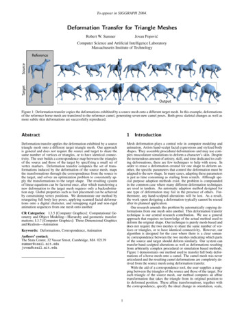
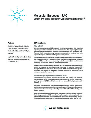
performed exhibit this effect; bond conformation changes start at the edges of thematerial and move towards the center. As the deformation process is far from anequilibrium process, this is not surprising.Since the force is applied at the edges, it must be transferred from segment tosegment. That process is not instantaneous, and if the force is sufficient to cause achange in conformation near the end of the chain, the resulting increase in bondlength may accommodate for the present loading conditions and halt the process.Thus, at any given time, it is more likely to find short bonds near the center. However,this is significantly affected by the presence of a second phase, as discussed belowand in ref. [35].All bonds have already changed conformation around t 32. At this stage, thematerial remains practically unchanged until t 47. Since all bonds have changed tothe long conformation, there are no other mechanisms available for deformation ofthe material. The force has to increase substantially until it is high enough to breakprimary bonds, which occurs at t 47. More broken bonds appear at t 52 and thenumber of broken bonds continues to increase at every force step. At t 79 themajority of the bonds have been broken throughout the material, yet no large crackscan be observed. The first cracks appear in several locations simultaneously at t 80. These cracks continue to grow until the material fractures.The purely flexible material exhibits a random and homogeneous distribution ofconformation changes and broken bonds during deformation. This is reasonable,since all segments in the material are equal. However, the situation changes when aliquid crystalline (LC) second phase is added to the flexible matrix. The differentstages of the simulation of the 25% LC material are shown in Animation 2.Similarly to the flexible material, deformation is negligible for several force steps. At t 10, the first bond conformation changes are observed. In the subsequent forcesteps, bonds continue to change conformation. However, in the case of the twophase material, the first broken bonds appear at t 18 with most flexible bonds still inthe short conformation. The presence of the rigid LC islands induces this effect, asdiscussed in ref. [35].At t 25, several bonds have been broken but there are still a few bonds in the shortconformation. Small cracks can be identified in different loci at t 30. At this stage,although most bonds have gone through a conformation change, some can still befound in the short conformation. The cracks grow as more bonds continue to break.However, unlike the flexible material, it is possible to clearly distinguish regionswhere a crack developed and regions that have a low number of broken bonds. Thiseffect is quite noticeable at t 45. Thus, the presence of the islands influences crackformation and propagation.Since all segments are equal in the purely flexible material, cracks could be expectedto appear anywhere in the material and propagate randomly. However, this is not thecase of two-phase materials. In these, the morphology will determine where andwhen cracks will first appear as well as how they propagate through the material. Themorphology can be characterized in terms of second phase concentration and distribution, in order to predict crack formation loci and crack propagation patterns [36].The visual interpretation of Animation 1 and Animation 2 in terms of bond conformation changes during deformation can be confirmed by measuring the number ofbonds in each state during the simulation. The fraction of flexible bonds in the longconformation state, fc, is shown in Fig. 1.7
Fig. 1. Bond conformation changes during deformation for the one- and two-phasematerials. Here, fc is the fraction of flexible bonds in the long conformation state and εis the strainThe purely flexible material shows an almost linear increase of long bonds up to apoint where all bonds have changed conformation at high strain values. After thatpoint, further deformation can only be achieved through bond rupture. The 25% LCmaterial also exhibits linear increase of long bonds but with a higher slope, whichimplies that conformational changes are occurring sooner during the simulation.These materials never reach a state where all bonds have changed conformation.Furthermore, the maximum fc is reached at lower strain values than in the case of thepurely flexible material, which is due to LC islands limiting the conformation changesin their vicinity. Instead, bond rupture and crack growth enable deformation withoutfurther conformation changes.5.2. Deformation mechanisms in three dimensions (3D)Several mechanisms developing in systems of coiled chains created in three dimensions (3D) were not possible for aligned chains in 2D. First, the geometry of thechains allows chains to uncoil and orient themselves with the applied force. Also,since each chain in the material has a different length and the force is not applieddirectly to end-of-chain segments, chain separation can occur, for example through asliding mechanism. These two phenomena take place even at low force values, sinceit only requires breaking weak intermolecular forces. Last, chains can be entangled in3D materials, thus creating physical connection points. Depending on the extensionof the entanglement between two chains and their particular geometry, motion ofthose chains in opposite directions might be equivalent to a cross-link point and thusrequire rupture of primary bonds.In addition to these mechanisms of deformation, the mechanisms that were presented in section 5.1 for materials of oriented chains can also take place in 3Dmaterials of coiled chains. Besides rupture of primary bonds, flexible bonds canundergo bond conformation changes at relatively low values of the force. Thus, thesematerials exhibit competing deformation mechanisms, dependent on the structure of8
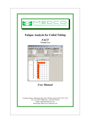
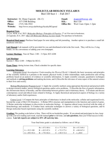
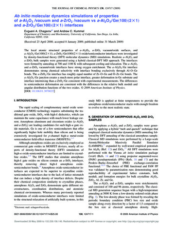
the material and loading conditions. The chain separation mechanism can be easilydemonstrated to occur during the deformation of coiled chains. For ease of visualization, a 2D material is considered, as shown in Fig. 2. It is easy to verify thepresence of chain separation in this simple material structure due to its small numberof chains. In larger materials, chain separation would occur in several locations simultaneously but would be difficult to identify and study.Fig. 2. Deformation through chain separation: a) initial material structure; b) adetailed view of the region where deformation will occur; c) two deformation lociappear at an early simulation stage; d) complete chain separation resulting inmaterial fractureIn order to demonstrate the existence of chain uncoiling during deformation, theevolution of specific chains can be followed, now in a 3D material; see Fig. 3a and b.At an intermediate stage of the simulation, as shown in Fig. 3c, the two chains thatextend through the material have suffered significant deformation, mostly throughuncoiling but also some bond conformation changes. The bonds that changed conformation are indicated by arrows. The rightmost chain remains nearly unchanged,since it is part of the edge of the material and in this case, deformation is taking placein the inner region.The geometry of the chains after several additional force steps is shown in Fig. 3d.The topmost chain has uncoiled and extended, becoming more orientated with thedirection of force application, although the number of long bonds remains the same.The bottom chain has been ruptured, and each part of that chain is now moving inopposite directions. Rupture occurred without complete bond conformation changesin this chain, due to the influence of neighboring chains. The rightmost chain stillexhibits only minor geometry changes.9
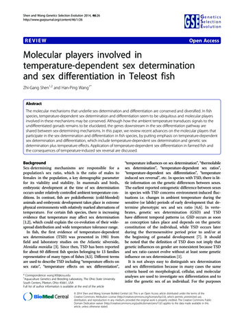
Fig. 3. Deformation through chain uncoiling: (a) structure of the material beforedeformation; (b) initial geometry of selected chains; (c) geometry of the selectedchains at an intermediate simulation stage; (d) geometry of the selected chains nearfracture. In (b), (c) and (d), segments not belonging to the three chains being studiedare represented only by dots for clarityFig. 4. Chain entanglements in 3D materials of coiled chains: a) two entangledchains; b) a detailed view of the entanglement. Only the two entangled chains arefully represented5.3. Chain entanglementsThe presence of entanglements in 3D materials of coiled chains is an importantfeature and can be graphically verified. The effect of molecular entanglement densityon the mechanical behavior of polymers has been reported by Seguela and Rietsch10
[45]. The material previously represented in Fig. 3 has two entangled chains, asshown in Fig. 4.The influence of this entanglement on the deformation of the material during thesimulation is shown in Animation 3. Fig. 5 represents different stages of thedeformation process, evidencing the influence of this entanglement in the interactionbetween the two chains.Fig. 5. Effect of chain entanglements on the behavior under tensile deformation: (a)intermediate stage of the simulation; (b) rupture of the entanglement precedingmaterial fracture. All segments in the material not belonging to the two entangledchains are represented only by dots for clarityThe two entangled chains undergo partial uncoiling and re-orientation with theexternal force, together with bond conformation changes, to allow chain extension.After a certain amount of deformation, the entanglement forces one of the chains toextend and eventually rupture to allow further material deformation. At this point, apiece of the ruptured chain is separated from the rest of it, being displaced along withthe other chain due to the entanglement; see again Animation 3.5.4. Second phase concentrationAs previously discussed, the presence and distribution of the LC islands is expectedto greatly influence the mechanical properties and behavior of the material.
subjected to an applied load. When compared to other polymers, PLCs exhibit a series of improved properties [4-6]. Due to their complexity, they have been concomitantly studied by statistical mechanics [7,8], viscoelastic models [9-11], and experimental methods [1,4-6]. Previous and ongoing results from computer simulations of PLCs can provide