Transcription
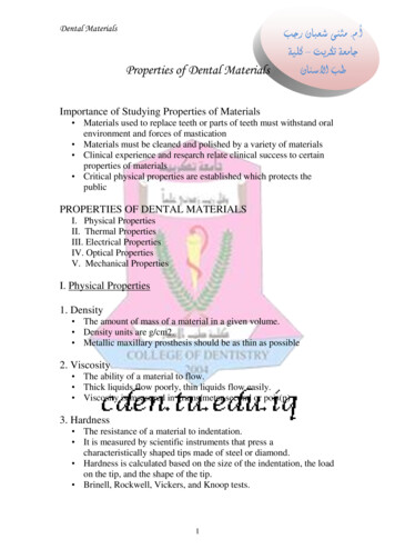
ArcelorMittal Europe – Flat ProductsDescription of mechanical propertiesIntroductionMechanical properties are governed by the basic concepts of elasticity, plasticity andtoughness.Elasticity is the capacity of a metal to undergo temporary deformation. As soon as the loadthat caused this deformation is removed, the metal returns to its original shape.Plasticity, or ductility, is the ability to undergo permanent deformation without failure.This property is used in metal forming in order to permanently modify the shape.Toughness represents the ability to absorb shocks without suddenly failing, and can beregarded as the opposite of brittleness.The aim of mechanical testing is to evaluate the behaviour of a material when subjected to amechanical load.Elasticity and plasticity can be defined from tensile test results and hardness measurements.Toughness is determined by an impact bending test.Tensile testsTesting procedureThis test involves subjecting a metal specimen to a slow, gradually increasing tensile load,in order to allow equilibrium to be constantly established between the imposed load and theinduced strain.The test-piece usually comprises two reference marks, initially spaced at a distance L0, knownas the initial gauge length. When a force F is applied to the specimen, the deformation causesthe gauge length to increase to a value L.Modern testing machines constantly record the gauge length as a function of the applied loadand directly plot a curve representing the variation of the strain L - L0 with stress (load perL0unit area) F .S0The following curve gives an example of the type of diagram obtained and illustrates thedeformation of the specimen during the test. 1
Description of mechanical propertiesStandard mechanical propertiesRe yield stress, yield strength or yield point,in MPa or N/mm2, corresponding to the endof the elastic region (point A in the diagram)RmRm ultimate tensile strength, in MPa orN/mm2 (point B in the diagram)ReA% total elongation at failure, in %(point C in the diagram, specimen 4)R FS0BCANeckingelongationUniform elongationA% 0The description of the test and the valuesto be measured are given in the standardEN ISO 6892-1:2009.S0L0L - L0x 100L0SLLuSuS0 Initial gauge length areaS Area during testSu Final area in neckLu Final lengthThree particular points can be seen on this curve, and are marked A, B and C. Between the origin 0 and A, the specimen’s elongation is proportional to the stress.If the stress is removed, the elongation returns to 0. The line segment 0A thus correspondsto the elastic region (specimen 1). Between A and B, the deformation is spread out in a uniform way over the test-piece(specimen 2). If the stress is released, the sample no longer returns to its initial length.This is the plastic region. Since the deformation is homogeneous over the whole of thespecimen, this range is called the uniform elongation region. Between B and C (specimen 3), the deformation becomes localised (“necking”), leading tofailure at point C.2
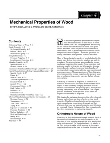
Description of mechanical propertiesHardness testsPrincipleIn this test, an indenter is forced into the metal to be characterised. The applied load isconstant, so that the softer the tested material, the larger the size of the permanentindentation (projected area, depth).Description of the testsIn general, two types of indenter are used, either a ball or a point. These two geometriesform the basis of the two major test categories, within which the size of the indenter andthe applied load can vary. Ball indenter: Rockwell (scales B, E and K), surface Rockwell (scale T), Brinell tests Point indenter: Vickers, Rockwell (scales A, C and D), surface Rockwell (scale N) testsRockwell testIn the HRB test, which is one of the most commonly used, a 1/16’’ diameter ball is pressedinto the sheet under a load F1 of 100 kgf, after having applied a preload F0, and the depth ofthe indentation is measured (see the following figures). The HRB scale is limited to values of100 HRB. Beyond this level, the HRC method is used, based on the same principle, but with aconical diamond indenter and an applied load F1 of 150 kgf.F0F0 F1F0F0F0 F1F0Coneαγβ0abα0.2 mmγHARDN SS100α0.26 mmHARDN SS130Samplesurfacee c-acabSamplesurfaceγββe c-acαγβ0HRB 130 - eHRC 100 - e 3
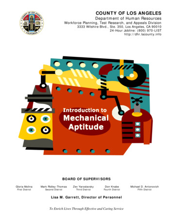
Description of mechanical propertiesVickers testThe end of the indenter is diamond-shaped in the form of a square-based pyramid.The load applied can vary from 5 to 100 kgf. The resulting hardness is calculated fromthe ratio of the applied load to the area of the indentation. In practice, the average of the twodiagonals of the impression is determined, the hardness value being read directly froma conversion table (see the figure below).Fd1136 d2HV 0.189 F/d2Penetrator apex angle 136 F test load in Newtons 1%d diagonal of imprint in mm (d1 d2)/2Values measuredDepending on the test, either the depth or the size of the indentation is measured.This value is compared to tables, which give a unitless number, as a function of the appliedload, characterising the hardness of the metal.RemarksThere is no reliable correlation between the hardness and the mechanical propertiesdetermined in a tensile test.This is due to the principle of the hardness measurements, which evaluates only the surfaceproperties of the material, whereas the tensile test characterises the entire volume.4
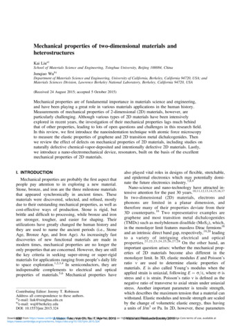
Description of mechanical propertiesImpact strengthTesting procedureThe test consists in measuring the energy required to break a V- or U-notched specimen,supported at two points, in a single blow. The impact strength is the energy, expressed injoules per cm2, necessary to break the notched specimen. It is usually measured in testingmachines based on a swinging pendulum, the most common type being the Charpy impacttester.Although standard full-size samples require a minimal thickness of 10 mm, standardisedsub-size samples exist as well for specimen thicknesses 5 mm.Impact strength (K) energy absorbed for fracture W (joules)area under the notch (cm2)Details of specimen and pendulum viewed from above(dimensions in mm)Schematic of impact test in mmPendulumPendulum30 r 2 to 2.5h0W1 P x h1h155W0 P x h 0105Specimen support(see detail)r 1 to 1.540SpecimensupportP Weight (N) - h0 Initial height (m) - h1 Final height (m)nergy absorbed on fracture W W0 - W1Values measuredThe impact strength is generally measured at room temperature, but for numerousapplications, it is necessary to know the behaviour of the material at low or very lowtemperatures.When impact strength measurements are made on the same steel at different temperatures,the resulting graph, called the transition curve, often has the shape shown in the followingfigure, with a ductile to brittle transition at low temperatures. 5
Description of mechanical propertiesda j/cm2200Ductile or tough100Brittle0TKTest temperature CAbove a temperature TK, a large amount of energy is necessary for fracture, which occursonly after extensive plastic deformation. The metal and the fracture are said to be ductile.Below TK, the energy necessary for fracture is much lower, and the specimen breakswithout significant plastic deformation. The metal and the fracture are said to be brittle.The temperature TK, situated half-way between ductile and brittle levels, is called thetransition temperature. The lower its value, the more suitable the material will be for use at lowtemperatures./ArcelorMittal Global R&D Gent – Photo Jeroen Op deBeeckCopyrightArcelorMittal Europe – Flat Products24-26, boulevard d’AvranchesL-1160 ittal.comindustry.arcelormittal.comAll rights reserved for all countries. This publicationshall not be reproduced, in whole or in part, in any formor by any means whatsoever, without prior expresswritten consent from ArcelorMittal. Care has beentaken to ensure that the information in this publicationis accurate, but this information is not contractuallybinding. ArcelorMittal and any other ArcelorMittalGroup company do not therefore accept any liability forerrors or omissions or any information that is found tobe misleading.As this document may be subject to change at anytime, please consult the latest information onindustry.arcelormittal.com/catalogue01/2016 - Published by ArcelorMittal Europe CommunicationsCredits
Description of mechanical properties 1 Introduction Mechanical properties are governed by the basic concepts of elasticity, plasticity and toughness. Elasticity is the capacity of a metal to undergo temporary deformation. As soon as the load that caused this deformation is removed, the metal returns to its original shape.