Transcription
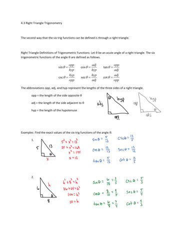
To appear in SIGGRAPH 2004.Deformation Transfer for Triangle MeshesRobert W. SumnerJovan PopovićComputer Science and Artificial Intelligence LaboratoryMassachusetts Institute of TechnologyTargetSourceReferenceOutputFigure 1: Deformation transfer copies the deformations exhibited by a source mesh onto a different target mesh. In this example, deformationsof the reference horse mesh are transfered to the reference camel, generating seven new camel poses. Both gross skeletal changes as well asmore subtle skin deformations are successfully reproduced.Abstract1Deformation transfer applies the deformation exhibited by a sourcetriangle mesh onto a different target triangle mesh. Our approachis general and does not require the source and target to share thesame number of vertices or triangles, or to have identical connectivity. The user builds a correspondence map between the trianglesof the source and those of the target by specifying a small set ofvertex markers. Deformation transfer computes the set of transformations induced by the deformation of the source mesh, mapsthe transformations through the correspondence from the source tothe target, and solves an optimization problem to consistently apply the transformations to the target shape. The resulting systemof linear equations can be factored once, after which transferring anew deformation to the target mesh requires only a backsubstitution step. Global properties such as foot placement can be achievedby constraining vertex positions. We demonstrate our method byretargeting full body key poses, applying scanned facial deformations onto a digital character, and remapping rigid and non-rigidanimation sequences from one mesh onto another.Mesh deformation plays a central role in computer modeling andanimation. Artists hand-sculpt facial expressions and stylized bodyshapes. They assemble procedural deformations and may use complex musculature simulations to deform a character’s skin. Despitethe tremendous amount of artistry, skill, and time dedicated to crafting deformations, there are few techniques to help with reuse. Inorder to reuse a deformation created for one shape to deform another, the specific parameters that control the deformation must beadapted to the new shape. In many cases, adapting these parametersis just as time consuming as starting from scratch. Although special purpose adaption methods exist, the problem is compoundedin the common case where many different deformation techniquesare used in tandem. An automatic adaption method designed forone type of deformation may fail in the presence of others. Furthermore, any hand-sculpted alterations will be lost. As a result,the work spent designing a deformation typically cannot be reusedafter its planned application.Our research amends this problem by automatically copying deformations from one mesh onto another. This deformation transfertechnique is our central research contribution. We use a generalapproach that requires no knowledge of the actual method used todeform the original shape. Our technique is purely mesh-based anddoes not require the two meshes to share the same number of vertices or triangles, or to have identical connectivity. However, ouralgorithm is designed for the case where there is a clear semantic correspondence between the two meshes indicating which partsof the source and target should deform similarly. Our system cantransfer hand-sculpted alterations as well as deformations resultingfrom arbitrarily complex procedural or simulation based methods.Figure 1 demonstrates our method used to transfer full body deformations of a horse mesh onto a camel. The camel mesh was neverarticulated and the resulting camel deformations are completely derived from the source mesh using deformation transfer.With the aid of a correspondence tool, the user supplies a mapping between the triangles of the source and those of the target. Foreach triangle of the source mesh, our method computes an affinetransformation that takes the triangle from its original position toits deformed position. These affine transformations, together withthe correspondence, specify the ideal change in orientation, scale,CR Categories: I.3.5 [Computer Graphics]: Computational Geometry and Object Modeling—Hierarchy and geometric transformations; I.3.7 [Computer Graphics]: Three-Dimensional Graphicsand Realism—AnimationKeywords: Deformations, Correspondence, AnimationAuthors’ contact:The Stata Center, 32 Vassar Street, Cambridge, MA duction
To appear in SIGGRAPH 2004.as single-weight enveloping or skeleton-subspace deformation deforms mesh vertices by blending deformations of nearby skeletonbones. New target meshes can be swapped in by binding their vertices to the appropriate bones and setting the desired vertex weights.Furthermore, the motion of the skeleton can be parameterized byjoint angles to define a set of natural control parameters for directanimation of the mesh with keyframing, or for retargeting motionfrom a skeleton of a different size and proportion [Gleicher 1998].Deformation transfer is the first step toward the development ofsimilar techniques for the animation of meshes with non-skeletaldeformations or without an obvious skeletal structure. It generalizes the binding concept, which maps the motion of mesh verticesto the motion of a skeleton, by mapping deformations of the targetmesh to deformations of the source.Deformation transfer can have an immediate impact on examplebased techniques, which currently rely on the artist to specify example shapes. Pose-space deformation, for example, corrects the “collapsing elbow” and other problems associated with simple skeletondriven deformations by enabling the artist to sculpt corrective deformations [Lewis et al. 2000]. Once these corrections have beensculpted, deformation transfer can reduce the effort required toadapt them to new meshes. Bregler et al.’s cartoon-capture technique encodes a motion in the coefficients of a linear combinationof meshes, which describe the animated character in a selection ofkey poses [2002]. Mapping these motions onto a different characterrequires an artist to recreate the new character in every single pose.Deformation transfer requires only one pose for the new character and automates the reproduction of the remaining poses. If theentire configuration space of the character is described in this manner [Ngo et al. 2000; Sloan et al. 2001], deformation transfer couldlead to a technique for mapping the articulation from one characterto another.and skew of each triangle of the target shape. However, these idealtransformations will not, in general, be consistent with respect toone another: applied directly without modification, the transformations would not preserve the connectedness of the target mesh.Therefore, to find the deformed target shape, deformation transfer solves an optimization problem such that the ideal changes arematched as closely as possible while maintaining consistency. Theretargeting process is numerically efficient, as the system of linear equations for a source/target pair can be factored and stored ina precomputation step. Transferring a new deformation from thesource to the target requires only performing backsubstitution withthe stored factorization. Global properties such as foot placementcan be achieved using positional vertex constraints.2BackgroundDeformation transfer is a generalization of the concept introducedby expression cloning, which transfers facial expressions from oneface mesh to another [Noh and Neumann 2001]. In this approach,each expression is encoded with vertex displacements that definethe differences between the reference face and the expression face.Expression cloning uses heuristics designed to adapt the directionand scale of displacement vectors to account for faces of differingshape and proportions. This representation and adaptation technique is specialized for the deformations that arise in facial expressions. Our method transfers arbitrary nonlinear deformations bycomputing an optimal global deformation of the target shape.One way to represent such a global deformation is with a freeform deformation [Sederberg and Parry 1986] in which a lattice ofcontrol points induces a deformation on the enclosed space. Withthis or a similar representation, any target mesh can be deformedwith ease by applying the global deformation to every mesh vertex. The Inkwell 2D system uses precisely this strategy to animatedifferent 2D characters with the same set of hand-animated Coonspatches [Litwinowicz 1991]. However, this approach is harder togeneralize when the source deformation is not initially describedby a free-form deformation or a similar representation. In thesecases, the method must infer both the structure of the control latticeand the position of its control points, or, less optimally, solve forthe control points of a specific lattice structure [Hsu et al. 1992].A fixed lattice structure is not optimal, because a reasonably sizedlattice cannot express arbitrary nonlinear deformations of verticesfor every target mesh [Singh and Fiume 1998].Deformation transfer resolves this problem by using locallyspecified deformations [Barr 1984], which can define any globalnonlinear deformation of mesh vertices. This approach extends theideas from Alexa, Cohen-Or, and Levin’s [2000] shape interpolation technique which maximizes the rigidity of a blended shape bycomputing the optimal deformation of its interior. We show thatthe interior of the target mesh need not be considered for transferof mesh deformation. Our boundary formulation has tremendouspractical advantages. It greatly simplifies the numerical complexityof the transfer process and makes it easier to specify regions thatshould move similarly.The concept of deformation transfer can be posed as an analogy: given a pair of source meshes, S and S 0 , and a target mesh T ,generate a new mesh T 0 such that the relationship between T andT 0 is analogous to the relationship between S and S 0 . This form ofreasoning was used to transfer drawing styles between two curves[Hertzmann et al. 2002]. Deformation transfer applies in the specific case where the relationship between S and S 0 is a continuousglobal deformation of the space and not an arbitrary relationship.This specialization enables optimal reproduction of the source deformation on the target mesh. Furthermore, deformation transferdoes not require a common parameterization of the source and target meshes. Instead, it employs source and target meshes withmatching reference poses much like facial animation uses a neutral face or skeleton-based techniques use a mesh in the T-pose.When the deformation of a triangle mesh is purely skeletondriven, transfer is more straightforward. A simple technique known3Deformation TransferThe goal of deformation transfer is to transfer the change in shapeexhibited by the source deformation onto the target. We representthe source deformation as a collection of affine transformations tabulated for each triangle of the source mesh. We use this representation because the non-translational portion of each affine transformation encodes the change in orientation, scale, and skew inducedby the deformation on the triangle. However, the three vertices ofa triangle before and after deformation do not fully determine theaffine transformation since they do not establish how the space perpendicular to the triangle deforms. To resolve this issue, we add afourth vertex in the direction perpendicular to the triangle. Let viand ṽi , i 1 . . . 3, be the undeformed and deformed vertices of thetriangle, respectively. We compute a fourth undeformed vertex aspv4 v1 (v2 v1 ) (v3 v1 )/ (v2 v1 ) (v3 v1 ) (1)and perform an analogous computation for ṽ4 . We scale the crossproduct by the reciprocal of the square root of its length sincethis causes the perpendicular direction to scale proportional to thelength of the triangle edges.An affine transformation defined by the 3 3 matrix Q and displacement vector d, which, for notational convenience, we write asQ d, transforms these four vertices as follows:Qvi d ṽi ,i 1 . . . 4.(2)If we subtract the first equation from the others to eliminate d andrewrite them in matrix form treating the vectors as columns, we getQV Ṽ whereV [v2 v1 v3 v1 v4 v1 ].Ṽ [ṽ2 ṽ1 ṽ3 ṽ1 ṽ4 ṽ1 ](3)A closed form expression for Q is given byQ ṼV 1 .2(4)
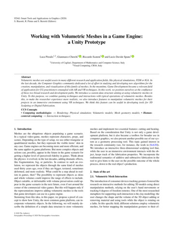
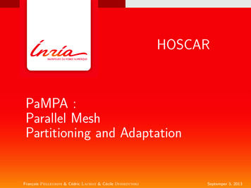
To appear in SIGGRAPH 2004.TargetSourceReferenceABCFigure 2: We encode a source deformation with an affine transformation for each source triangle and relate the transformations to the targetthrough a user supplied triangle correspondence. (A) Using only the non-translational component of the source transformations transfers thechange in orientation and scale to the target triangles but does not position them appropriately relative to their neighbors. (B) Using the sourcedisplacements gives a disconnected shape since consistency requirements are not enforced. (C) Deformation transfer solves a constrainedoptimization problem for a new set of target transformations that are as close as possible to the source transformations while enforcing theconsistency requirements: shared vertices must be transformed to the same place.We use Equation 4 to compute the source transformationsS1 , . . . , S S that encode the change in shape induced by the deformation, where S refers to the set of triangle indices for the sourcemesh.In order to relate the source deformation to the target mesh withthe set of triangle indices T , the user supplies a mapping M betweenthe set indices for the source and target triangles:M {(s1 ,t1 ), (s2 ,t2 ), . . . , (s M ,t M )}.j p(v) i, j, k p(vi ), vTj v dj Tk v dk vk p(v)k p(v)j p(v).Figure 3: In order to maintain consistency, the affine transformations for all triangles j, k p(v) that share vertex v must transformv to the same position.(5)A pair (si ,ti ) indicates that the target triangle with index ti shoulddeform like the source triangle with index si . This mapping allowstransferred deformations to originate from any region of the sourcemesh. There are no restrictions on M. In most cases, it is a generalmany-to-many mapping, but it can also be bijective (one-to-one andonto), surjective (onto), or not-onto. This generality enables transfer between meshes of different tessellations.Our strategy is to transfer the source transformations via the correspondence map to the target. The non-translational portion S ofa source affine transformation S d encodes the change in triangleshape induced by the source deformation. However, we cannot apply S directly to the corresponding target triangle since S encodesonly the change in orientation and size and not the positioning ofthe triangle relative to its neighbors (Figure 2 A). Furthermore, wecannot use the source displacement vectors to resolve this problemsince their lengths depend on the size and position of the sourceshape. Doing so yields a discontinuous shape (Figure 2 B) and exposes the fact that our deformation representation affords too manydegrees of freedom. It allows the triangles to be transformed arbitrarily even though neighboring triangles share vertices.In order to ensure that the affine transformations, when appliedto the target mesh, are consistent with respect to one another, werequire that shared vertices be transformed to the same place (Figure 3). For the set of target affine transformations T1 d1 . . . T T d T this requirement isT j vi d j T k vi dk ,vaffine transformations: M minT1 d1 .T T d T subject to j 1Ss j Tt j2FT j vi d j T k vi dk ,(7) i, j, k p(vi ).The matrix norm · F is the Frobenius norm, or the square root ofthe sum of the squared matrix elements.A solution of this optimization problem defines a continuous deformation of the target mesh up to a global translation. The globaltranslation can be defined explicitly by setting the displacement difor any target triangle. In addition, other positional constraints suchas foot placement can also be added.4Vertex FormulationAlthough the formulation of deformation transfer in Equation 7 canbe solved with quadratic programming techniques, a more efficientmethod eliminates the constraints by reformulating the problem interms of vertex positions. The key idea is to define the unknown target transformations in terms of the triangles’ vertices. Then, ratherthan solving for the entries of the affine transformations, we solvedirectly for the deformed vertex positions. This method satisfiesall constraints because, by construction, any shared vertex will betransformed to the same location.For each target triangle, we add a fourth undeformed vertex(Equation 1) and write the non-translational portion of the affinetransformation in terms of the undeformed and deformed verticesT ṼV 1 . The elements of V 1 depend on the known, undeformed vertices of the target shape. The elements of Ṽ are the coordinates of the unknown deformed vertices. Thus, the elements ofT are linear combinations of the coordinates of the unknown deformed vertices.(6)where p(vi ) is the set of all triangles that share vertex vi .In order to transfer the source deformation onto the target meshwhile maintaining these consistency requirements (Figure 2 C),deformation transfer minimizes the difference between the nontranslational components of the source and target transformationsand enforces the consistency constraints in Equation 6 by solving the following constrained optimization problem for the target3
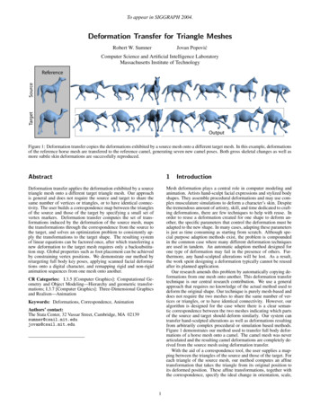
To appear in SIGGRAPH 2004.Given this definition, we rewrite the minimization problem as M minṽ1 .ṽn j 1Ss j Tt j2.F(8)Since the target transformations are defined in terms of the unknown deformed target vertices, the minimization is over the vertices themselves and the continuity constraints are implicitly satisfied. Positional vertex constraints can be enforced by simply treating a vertex as a constant rather than as a free variable.The solution to this optimization problem is the solution to asystem of linear equations. Rewriting the problem in matrix formyields(9)min c Ax̃ 22Aṽ1 .ṽn(10) T EI (v1 . . . vn ) Ti I 2F .EC (v1 . . . vn , c1 . . . cn ) T i 1 j adj(i) Ti T j 2F .n vi ci 2 ,(13)i 1where ci is the closest valid point on the source mesh to target vertexi. When computing the closest valid point, vertex normals of thesource mesh are compared with triangle normals of the target meshand a difference in orientation of less than 90 indicates a validpoint. A grid-based spatial sorting algorithm accelerates the closestpoint computation.To compute the deformed vertices ṽ1 . . . ṽn of the source mesh,we define the following minimization problemThe correspondence between the source and target triangles defineshow the deformation of the source mesh should be transferred tothe target. We aid the creation of this mapping with a tool that automatically computes the triangle correspondence from a small set ofm user selected marker points. Our correspondence technique is aniterated closest point algorithm with regularization, aided by userselected marker points, that deforms the source mesh into the targetmesh. Then, it computes the triangle correspondence by searching for pairs of source and target triangles whose centroids are inclose proximity. Figure 4 illustrates this process. Our correspondence system is similar to the template fitting procedure describedby Allen, Curless, and Popović [2003] but developed in the contextof our numerical framework.The correspondence system solves a minimization problem similar to the one we use for deformation transfer, but the objectivefunction is designed to deform one mesh into the other, rather thandeforming it like the other deforms. The user controls the deformation by supplying a set of marker points specified as pairs of sourceand target vertex indices. Each pair indicates that the source vertex, after deformation, should match the location of the target vertex. These markers are enforced as constraints in the minimization.The objective function contains a term that enforces deformationsmoothness, one that prevents over smoothing, and one that movesthe source vertices to the target mesh.Deformation smoothness, ES , indicates that the transformationsfor adjacent triangles should be equal. For a mesh with n vertices,we let T be the set of triangle indices and T1 d1 . . . T T d T bethe affine transformations that define the deformation. Then, (12)i 1The purpose of this term is to prevent the deformation smoothnessterm from generating a drastic change in the shape of the mesh inorder to achieve optimal smoothness.The closest valid point term, EC , indicates that the position ofeach vertex of the source mesh should be equal to the closest validpoint on the target mesh.CorrespondenceES (v1 . . . vn ) DHere, T1 , . . . , T T are defined in terms of the target vertices according to Equation 4, and adj(i) is the set of triangles adjacent to triangle i. Note that this term is minimized when the change in deformation, and not the mesh itself, is smooth. For example, regardlessof the smoothness of the mesh, any rigid transformation applied toall triangles is a valid minimum for ES .Deformation identity, EI , is minimized when all transformationsare equal to the identity matrix:The entries in A depend only on the target mesh’s undeformed vertex locations. Furthermore, the system is separable in the spatialdimension of the vertices. Thus, for each source/target pair, wecompute and store the LU factorization of AT A only once. Retargeting any source deformation onto the target mesh only requiresperforming backsubstitution to solve separately for the x, y, and zcomponents of the deformed target vertices. For efficiency, we usea sparse LU solver [Davis 2003]. Since the columns of A correspond to the unknown deformed target vertices, and since we addan extra vertex for each triangle, the number of columns of A (andhence the number rows and columns of AT A) is equal to the numberof vertices plus the number of triangles of the target mesh. Table 1lists the vertex and triangle counts for the meshes in this paper, andTable 2 lists the factorization and average backsubstitution times.5CFigure 4: The correspondence algorithm deforms the source meshinto the target, controlled by user selected marker points shown inyellow. (A) Target mesh. (B) Source mesh. (C) Source mesh afterthe first phase of deformation where the closest valid point termis ignored. (D) Final deformed mesh using all three terms of theobjective function.where x̃ is a vector of the unknown deformed vertex locations, c isa vector containing entries from the source transformations, and Ais a large, sparse matrix that relates x̃ to c. Setting the gradient ofthe objective function to zero gives the familiar normal equations:AT Ax̃ AT cBminṽ1 .ṽnE(v1 . . . vn , c1 . . . cn ) wS ES wI EI wC ECsubject toṽsk mk ,k 1.m(14)where wS , wI , and wC are weights, sk is the source vertex index formarker k, and mk is the position of marker k on the target mesh. Wesolve this minimization in two phases. In the first phase, we ignorethe closet point term by using weights wS 1.0, wI 0.001, andwC 0. We solve the problem for the deformed source mesh (Figure 4 B). The marker points of the deformed mesh will match exactly since they are specified as constraints, and the rest of the meshwill be carried along by the smoothness and identity terms. We usethis initial estimation to compute a set of valid closest points. Then,in the second phase, we solve the same problem increasing wC eachtime and updating the closest points after each iteration. PreservingwS 1.0 and wI 0.001 while increasing wC in four steps from1.0 to 5000.0 produced good results in our tests. Each time theminimization problem is solved, the source mesh is deformed fromits original undeformed state. Since wC increases, the source meshmore closely approximates the target mesh after each iteration (Figure 4 C).Once the source mesh has been deformed to match the shape ofthe target mesh, we compute the triangle correspondences by comparing the centroids of the deformed source and target triangles.(11)4
To appear in SIGGRAPH e/CamelCat/LionFace/HeadHorse/FlamingoLU ion0.293s0.057s0.298s0.406sTable 2: The number of correspondence markers used and the timing results for our examples on a 3.0GHz Pentium IV machine.Table 1: Number of vertices and triangles for our example meshes.captured and adapted to the target head. This type of transfer mightbe used when a digital stand-in must replace a real actor, or to mapthe facial expressions of a voice actor onto an animated character.Since the scanned data is in the form of face masks and the targetmesh consists of an entire head and neck, the mapping between thesource and target triangles is not onto. Only a subset of the targettriangles (those of the front of the face) are listed in the correspondence. We specify that the deformation of the remaining target triangles should be minimal by mapping them to the identity matrix.Our deformation transfer technique was designed for the casewhere there is a clear semantic correspondence between the sourceand target. We chose anatomically similar meshes to demonstrateour results since they have an obvious mapping (i.e., leg to leg, headto head, etc.). In Figure 8, we challenge this assumption by transferring the horse deformation onto a flamingo mesh. The correspondence is ambiguous as the flamingo has only two legs, no tail, and abeak. We mapped the flamingo’s legs to the horse’s front two legs,the flamingo’s body to the entire horse’s body including its tail, andits beak to the horse’s head. Building this mapping pushes the limits of our correspondence system as the flamingo’s “S”-shaped neckmust be unbent to match the horse’s straight neck. The deformationsmoothness term (Equation 11) fights against these large local deformations, requiring the user to select many marker points alongthe neck. However, once the correspondence has been adequatelyspecified, the flamingo faithfully deforms like the horse. Of course,a real flamingo’s hips bend in the opposite direction of a horse’sfront hips, which demonstrates a reason why deformation transferbetween anatomically different meshes may not be appropriate.None of the source and target meshes in our examples share thesame number of vertices, triangles, or connectivity. Table 1 liststhis geometric information about each model, and Table 2 givestiming results for each example. Our method is extremely fast.For example, the camel mesh, consisting of 21, 887 vertices and43, 814 triangles, required only 1.559 seconds for factorization and0.293 seconds on average to solve for each retargeted pose. Theuser time required to add the markers and compute the correspondence for each example was under one hour.Two triangles are compatible if their centroids are within a certainthreshold of each other and the angle between their normals is lessthan 90 . This compatibility test prevents two nearby triangles withdisparate orientation (e.g., triangles from the upper and lower lipsof a face) from entering the correspondence. For each triangle ofthe deformed source, we compute the closest compatible triangle(if any) of the target mesh and add the pair to the correspondencelist. Likewise, for each triangle of the target, we compute the closest compatible triangle of the deformed source mesh and add thatpair. This process ensures that all triangles of the source and target meshes, subject to the compatibility restriction, will be listedamong the correspondences. A target triangle may correspond tomany source triangles, and vice versa. This feature allows our deformation transfer method to accommodate meshes with differingnumbers of vertices and triangles.6Number ofMarkers65774273ResultsFigure 1 shows deformations of a horse transfered onto a camel.The reference horse mesh, shown in the gray box, is deformed intoseven key poses. The key poses include obvious skeletal deformations such as bending of the legs or neck as well as more subtle skindeformations like stretching near the joints. The input to our algorithm is the reference horse mesh, the seven deformed horse poses,the reference camel mesh, and the correspondence between the tworeference meshes. Given this data, deformation transfer generatesseven new camel poses by transferring the source deformations ontothe reference camel. Both the gross skeletal changes as well asthe more subtle skin deformations are faithfully reproduced on thecamel. Figure 5 demonstrates a similar set of deformations. Here,key poses of a cat are retargeted onto a lion. Since deformationtransfer copies the change in shape induced by the deformation, werequire the source and target reference meshes to have the samekinematic pose when skeletal deformations are retargeted.While the deformations of Figures 1 and 5 are primarily skeletalin nature, Figure 6 demonstrates the effectiveness of our approachwith non-rigid deformations. Here, the horse collapses as if it weremade of a rubber sheet. Its legs buckle and its entire body falls tothe ground, folding on top of itself. The deformations are transferedto the camel, and its body buckles and collapses similarly.In the accompanying video, we use deformation transfer to retarget two deformations that vary continuously through time. First,we transfer a gallop gait from the horse to the camel, and thenwe transfer the collapsing motion from Figure 6. In order to resolve the global positionin
cic case where the relationship between S and S0 is a continuous global deformation of the space and not an arbitrary relationship. This specialization enables optimal reproduction of the source de-formation on the target mesh. Furthermore, deformation transfer does not require a common parameterization of the source and tar-get meshes.