Transcription
User’s GuidePowerAlert Local SoftwareNote: PowerAlert is not required to operate your UPS System.For the latest PowerAlert updates, go to www.tripplite.com1. Introduction2. Requirements3. Installation3.13.2223Windows InstallationLinux Installation4. Initial Configuration5. 56Status SummaryStatus DetailActions ControlActions LoadsSettings DeviceSettings EventsSettings ContactsSettings SystemSettings SchemesLogs EventsLogs DataHelp7891011131517192021226. Frequently Asked Questions7. Troubleshooting8. Technical Support2324251111 W. 35th Street, Chicago, IL 60609 USA www.tripplite.com/supportCopyright 2018 Tripp Lite. All trademarks are the sole property of their respective owners.1
1. IntroductionIntended for home and small business applications, PowerAlert Local (PAL) software installs on a desktop PC or networkedserver and allows the computer to communicate with a UPS system through a serial or USB cable connection. This softwarecan be used to monitor power conditions, control your UPS system and enable automatic computer shutdown in the event of apower failure.PAL also allows your UPS system to appear as an SNMP-manageable device on your network, enabling remote monitoring andcontrol via PowerAlert Network Management System (PANMS) software or a third-party Network Management System. If youhave two UPS systems connected to a computer to provide redundant backup power, PAL can manage both UPS systems. Thelatest version of PAL has a self-contained, compatible version of Java Runtime Environment (JRE), which allows it to operateindependent of any other JRE version installed on the computer.2. RequirementsPAL works with Microsoft Windows and Linux computing platforms. The minimum system requirements for each platform are:Windows 7, 8, 10 (32 & 64 bit), Server 2008, 2012, 2016 (32 & 64 bit) Pentium 4 CPU 256 MB RAM Available USB or serial port TCP/IP network connection (required in order for the UPS system to appear on the local network as an SNMP-manageabledevice)Linux Fedora 8 or OpenSUSE 11 Supported RS-232 and USB UPS Available TTY port Open 3664 and 3665 ports (any firewall) Root user privileges (required for installation)2
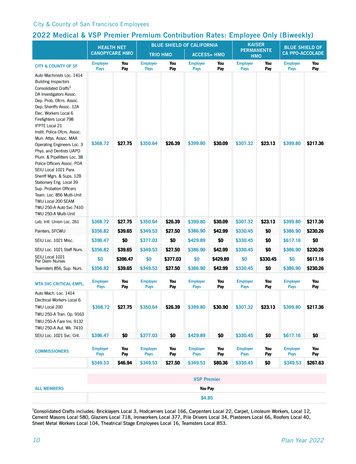
3. InstallationDownload the latest PAL installer from the Downloads tab at the following -local3.1 Windows InstallationUsing a USB or serial (DB9) cable, connect a communications port of your UPS system to a corresponding communicationsport of your computer. If your computer will be backed up by redundant UPS systems, repeat this cable connection procedurefor the second UPS system.Open the downloaded PowerAlert Local folder and double click on the pal-12.xxxxx86.exe file, then follow the on-screenprompts.Note: If a previous version of PAL is already installed on your computer, the PowerAlert Local installer will attempt to uninstall it beforeinstalling the newer version. However, Tripp Lite recommends uninstalling the previous version manually prior to installation of the newerversion.Click Next to continue.Review the License Agreement, select “I accept the terms in the license agreement” and click Next.3
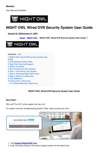
3. InstallationClick Install to begin the installation.A progress indicator will display the status of the installation. It may take several minutes for the installation to complete,depending on the connection speed.4
3. InstallationWhen the installation has completed, click Finish.3.2 Linux Installation1. Copy the appropriate software file to your local machine and enter the following as its root: rpm -i rpm-file-name [--nodeps]. Use the RPM main page to help you through any installation issues.2. PowerAlert will install to the directory /var/tripplite/poweralert, and will locate the pald daemon/service process within/var/tripplite/poweralert/engine. To control the status parameters and actions of the daemon/service, type ./[ pald] fromthe /etc/init.d directory.4. Initial ConfigurationAfter installation, PAL will detect your UPS system automatically. If your UPS system is not detected, refer to section5.5 Settings Device for possible solutions.Notable default settings for PAL are shown below. If you want to change any of these default settings, refer to the indicatedsection for configuration instructions.SettingDefault ValueConfiguration SectionOn Battery EventNot Configured5.6 Settings EventsLow Battery EventShut Down Computer 15 seconds after EventShut Down UPS System 2 minutes after Event5.6 Settings EventsEmail Notification SettingsNot Configured5.7 Settings ContactsSNMP Trap SettingsNot Configured5.7 Settings ContactsUser Level (Scheme)Depends on UPS System Detected5.9 Settings SchemesRamp / ShedRemain Off/Remain On5.5 Settings DeviceSYSLOGNot Configured5.8 Settings SystemTable 4 – Default Values for Settings5
5. OperationThe PowerAlert Console is PowerAlert Local’s primary user interface (Figure 5.1). It displays information about your UPS systemand power conditions, provides a direct UPS system control interface and allows you to configure automatic responses tochanges in conditions (such as automatic shutdown of your computer during power failures).Clicking the Tripp Lite logo in the header opens Tripp Lite’s Web site in a new browser window. The header also contains themenu buttons and submenu buttons, which are the main navigational elements of the PowerAlert Console. The menu buttonsare larger than the submenu buttons. Clicking a menu button selects that menu section and reveals the correspondingsubmenu buttons.The left side of the PowerAlert Console window contains several informational fields. The two uppermost fields display the IPaddress that PAL is using for SNMP proxy purposes (identical to your computer’s current IP address) and the device namefor the UPS system that is currently selected. If you have more than one UPS system connected to your computer, you canchoose which one will be active in the PowerAlert Console window by selecting it from the drop-down menu. The device namesare user-editable. The next three fields display the manufacturer, model name and location of your UPS system; the locationfield is user-editable (see 5.5 Settings Device for instructions on changing user-definable fields). The last three fieldsdisplay alarm information. These fields will be blank when there is a green check mark by the Alarm Status heading. They willchange only if there is an alarm, such as an “on battery” event. The icon will change to indicate alarm type and the fieldsbelow will display information about the affected UPS system, the cause of the alarm and the automatic or recommendedresponse to the alarm (see 5.6 Settings Events for a list of alarm types and their corresponding icons). Clicking the“Device” button will display information about the device that is experiencing the alarm condition. Clicking the “Log” button willopen the PowerAlert event log (see 5.10 Logs Events for more information).The remainder of the PowerAlert Console window contains information and/or controls that change with each menu andsubmenu selected. The information and controls shown will vary, depending on UPS model and environmental conditions. Inaddition, there are two user-level settings in PAL that will change the extensiveness of the user interface. This User’s Guideshows all the controls and information available in the Business Device Management Scheme, which is the setting for moreadvanced users. See 5.9 Settings Schemes for instructions on changing the user-level setting. The default user levelsetting depends on the UPS system that is detected by PowerAlert.6
5. Operation5.1 Status SummaryOn launching the PowerAlert Console, the Status Summary window (Figure 5.1) will display. This window containsinformation about environmental and operating conditions. Four additional buttons within the window allow you to select Inputinformation, Output information, Battery information and Miscellaneous information. Information such as Input Voltageis updated periodically. PAL continually queries the device for status information and updates the console as changes arereported. A status indicator appears in the upper right part of each button. If the indicator is green, all functions within thatcategory are operating within normal parameters. If the indicator changes color, one of the variables in that category is outsidenormal parameters.Figure 5.1 – PowerAlert Console window7
5. Operation5.2 Status Detail(Available in Business Scheme only)Click the Status menu button and the Detail submenu button to display the Status Detail window (Figure 5.2). This windowconsolidates the information contained in the four Status Summary information categories. It may also display additionalinformation categories, depending on the UPS system. Two gauges display the Input Voltage and Battery Charge level. Rightclick either gauge to display a pop-up menu that shows a list of variables. Select an alternate variable from the menu tochange the information displayed on the gauge (available with select UPS systems only).Figure 5.2 – Status Detail window8
5. Operation5.3 Actions Control(Available in Business Scheme only)Click the Actions menu button and the Control submenu button to display the Actions Control window. Click the“Control List” tab (Figure 5.3) to see UPS system and computer commands that you can execute immediately or schedulefor automatic execution. To execute a command immediately, select it from the drop-down menu and press the “ExecuteCommand” button. To schedule a command, select it from the drop-down menu, set the desired time and frequencyparameters and press the “Add Action” button. Certain commands have operational parameters that you can change to suityour requirements; they will be shown in the “Parameters” area. Available commands include: Operating System Shutdown Operating System Restart Cancel Shutdown Reboot UPS Initiate Self-Test Cycle All Loads Cycle Load Turn Load Off Turn Load On Turn All Loads Off Turn All Loads OnFor a complete list of commands available for your UPS system, refer to the drop-down menu. Click the “Control ScheduleSummary” tab to see a list of scheduled commands for the currently selected device. To remove a command from theschedule, highlight it and press the “Remove Event” button. The maximum number of scheduled commands is 64.Figure 5.3 – Actions Control Control List tabEconomy Mode (available on select UPS systems) configures an online UPS to function as a line-interactive UPS. In EconomyMode [and while AC utility power is available] the UPS operates at increased efficiency levels, thereby reducing its operatingcost. It will switch to battery power if AC utility power is interrupted or out of the acceptable range. To enable Economy Mode,select either “Enable Economy Mode” or “Set Economy Mode”, depending on the UPS. If the UPS has “Set Economy Mode”,enter a “2” in the “Parameters-Value” field, then click the Execute Command button. On the front panel of the UPS system,the “LINE” and “LOAD” LEDs will illuminate green and the “BYPASS” LED will illuminate solid yellow when the UPS system is inEconomy Mode.9
5. Operation5.4 Actions Loads(Available in Business Scheme only)Click the Actions menu button and the Loads submenu button to display the Actions Loads window (Figure 5.4). You cancontrol the outlets of the UPS system by pressing the appropriate “On,” “Off” or “Cycle” button. The load of the equipmentattached to the UPS system is displayed as a percentage of maximum capacity, allowing you to see whether additionalequipment can be added to the UPS system safely.Note: Loads fluctuate with the power demands of connected equipment. It is prudent to limit the load to approximately 80% of the UPSsystem’s maximum capacity in order to accommodate higher startup power demands and other increased power needs.The main control buttons affect all outlets. If your UPS system has switchable load banks, additional buttons allow you tocontrol each load bank. You can use the “Description” field to label the banks for easy reference. If the load bank(s) are nonswitchable, the control buttons will be greyed out.Warning: The load controls start or stop the flow of electricity to your UPS system’s outlets. Make sure youknow which equipment is connected to each load bank before attempting to use these controls.Figure 5.4 – Actions Loads window10
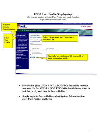
5. Operation5.5 Settings DeviceClick the Settings menu button and the Device submenu button to display the Settings Device window (Figure 5.5.1). Inthe “Device Variables” tab, you can edit “Location,” “Region,” “Device Name,” “Device ID”, “Date Installed”, “Low BatteryWarning” and “Battery Age Alarm Threshold”.Notes: Displayed device variables will vary by UPS model. The “Low Battery Warning” field is tied to the “Battery Below Warning Level” event. “Battery Age Alarm Threshold” is based on either the “Date Installed” entered on the Settings Device screen or the last “Battery InstallDate” set in the UPS. If “Battery Install Date” is not available, use “Set Last Battery Install Date” under the Action Control menu toenter the last “Battery Install Date.”Figure 5.5.1 – Settings Device windowIf PowerAlert Local has not yet detected a connected UPS system, click the Scan For New Devices button to initiate localdiscovery. In the rare event that PowerAlert Local still cannot detect a connected UPS system, you can try to add it manuallyby clicking the “Add Device” button. As shown in Figure 5.5.2, you will need to select the computer’s Communication Port(connecting to the UPS system) as well as the UPS system’s Communication Protocol. If your UPS system is still not detected,restart your computer to ensure that the UPS system has been recognized by your computer’s operating system. You mayalso need to modify the port and/or protocol you selected. If the selected device is inactive, you can click the “Delete Device”button to remove it from the device list.Figure 5.5.2 – Actions Add Device(s) window11
5. OperationIf the selected device supports load ramping and shedding, the “Ramp Settings” and “Shed Settings” tabs will display (Figure5.5.3). The “Ramp Settings” and “Shed Settings” tabs each contain a table that shows the numbered load segments availablefor the selected device. Each load segment has a “Device Description” field, an “Action” field and a “Delay” field. The “DeviceDescription” field allows you to enter a note about the equipment connected to the load segment. The “Action” field allowsyou to configure the load ramping or shedding behavior by choosing from the possible actions listed in the pop-up menu. The“Delay” field allows you to enter the delay (in seconds) before the specified action is performed. After entering the desiredvalues, click the Apply button. Load ramping sequences are applied when AC input power is switched on. Load sheddingsequences are applied when AC input power is lost. Load ramping and load shedding require a Tripp Lite UPS system or PDUwith controllable load banks (outlets that can be remotely switched on and off); such devices are referred to as autonomousdevices. The table below identifies load ramping and load shedding characteristics by device type.Custom Load RampingAutonomous DeviceNon-Autonomous DeviceCustom Load onRequires webcard orPowerAlertFunctions withoutwebcard or PowerAlertRequires webcard orPowerAlertFunctions withoutwebcard or PowerAlertNot supportedNot supportedRequires webcardRequires webcardTable 5.5 – Load Ramping and Shedding CharacteristicsFigure 5.5.3 – Settings Ramp Settings12
5. Operation5.6 Settings EventsClick the Settings menu button and the Events submenu button to access the Settings Events window. The content of theSettings Events window will differ, depending on which Device Management scheme (Home or Business) you have enabled.For more information about choosing schemes, see 5.9 Settings Schemes.If the Home Scheme is active, the Settings Events window will display configurable options for how your computer willrespond when your UPS system is operating from battery power (Figure 5.6.1).Figure 5.6.1 – Settings Events window, Home Device Management schemeIf the Business Scheme is active, the Settings Events window displays a more extensive set of controls (Figure 5.6.2).Events are divided into five categories—Critical, Warning, Status, Info and Offline—each with its own icon. This icon (along withother event information) will display in the left-hand Alarm Status section of the PowerAlert Console window when an event ofthat category occurs.Figure 5.6.2 – Settings Events window, Business Device Management scheme13
5. OperationFor each Event type, you can set one or more actions. Check the “Status” box adjacent to the action item in order to enableit. Most actions have additional parameters that need to be set. Click on an individual Action, and then the “Settings.” buttonbelow the list. A new window will appear in which the parameters can be set. The table below identifies each of the actionsand their settings.ActionSettingsBroadcastThis feature is no longer supported; it was tied to Windows Messenger Service, which wasdiscontinued by Microsoft. An alternative would be executing a script to call a user-createdbatch file.Shutdown Select whether the event will shut down the operating system* Time to elapse before shutting down the operating system Select whether the event will shut down the device* Time to elapse before shutting down the deviceContact Notification Time to elapse before email notification is sent to the selected contacts Time between successive re-transmissions of the notification until the alarm is clearedSNMP Notification Time to elapse before SNMP traps are sent to the selected IP addresses Time between successive re-transmissions of the SNMP trap until the alarm is clearedExecute Script Time to elapse before executing the command script Enter the script or program path to execute when the time has elapsed Enter the script or program path to execute when the alarm has clearedLoggingNo settingsSet OID Event Raise/ Clear Enter the OID, Type, Value and Delay for the Raise event Enter the OID, Type, Value and Delay for the Clear eventTable 5.6 – Event Actions and Settings, Business Device Management Scheme14
5. Operation5.7 Settings Contacts(Available in Business Scheme only)Click the Settings menu button and the Contacts submenu button to display the Settings Contacts window. The “E-mail”tab (Figure 5.7.1) shows a table of configured e-mail contacts. Before PowerAlert can send e-mail notifications, you mustenter e-mail server information and add at least one e-mail contact. Click the “SMTP Settings” button to enter the settings foryour local mail server in the SMTP Settings window (inset image). If you do not know the correct settings, contact your networkadministrator. Add a new e-mail contact by clicking the “New” button and entering the information requested in the pop-upwindow (Figure 5.7.2).The “SNMP” tab (Figure 5.7.3) shows a table of configured SNMP contacts. Before PowerAlert can send an SNMP trap to anIP address, you must add at least one SNMP contact. Add a new SNMP contact by clicking the “New” button and enteringthe information requested in the pop-up window (inset image). Before configuring SNMP traps or SNMP sets for an event,SNMP trap and/or SNMP set destinations must be added here first. For SNMP trap destinations, use port 162. For SNMP setdestinations, use port 161. If you do not know the correct settings, contact your network administrator.Note: You also need to configure and enable each event setting through the Settings Events window (see section 5.6 Settings Events) before notifications can be sent to your contacts.Note: If adding an SNMP contact to be used with an SNMP Set Notification, use port 161 or the port number that the remote SNMP devicecan be accessed on.Figure 5.7.1- Settings Contact Email, SMTP Settings15
5. OperationFigure 5.7.2- Settings Contact Email, New contactFigure 5.7.3- Settings Contact SNMP, New contact16
5. Operation5.8 Settings System(Available in Business Scheme only)Click the Settings menu button and the System submenu button to display the Settings System window (Figure 5.8.1).The “Shutdown” tab determines whether your computer will hibernate or shut down completely (hibernation also must beenabled through your computer’s operating system). Additional settings apply if you have multiple UPS systems connected toyour computer.Click the Write Config File button to create a file that contains most of the settings defined through the PowerAlert Console.You can use the configuration file as a backup or to aid the configuration of additional workstations. The configuration file issaved to C:\Program Files (x86)\TrippLite\PowerAlert\ by default.Figure 5.8.1 – Settings System ShutdownThe “Configuration” tab (Figure 5.8.2) contains the option to set an automatic update trap to a PowerAlert NetworkManagement System that is monitoring the PowerAlert Local System. The Discovery option allows the user to define ifPowerAlert should search for newly connected local devices at startup.Figure 5.8.2 – Settings System Configuration17
5. OperationSYSLOG is a protocol that allows a machine to send event notification messages across IP networks to event messagecollectors, known as SYSLOG servers. Up to 4 SYSLOG servers may be defined, by either IP address or Hostname, in the“SYSLOG” tab (Figure 5.8.3). Once configured, any event will trigger a message to be sent to the specified SYSLOG server(s).Figure 5.8.3—Settings System SYSLOG18
5. Operation5.9 Settings SchemesClick the Settings menu button and the Schemes submenu button to display the Settings Schemes window (Figure 5.9).PowerAlert Local has two user level settings: the “Home Device Management Scheme” and the “Business Device ManagementScheme.” The home scheme contains basic settings. Several PowerAlert Console windows will not be shown when the homescheme is active, including the Status Detail window, the Settings Contacts window, the Settings System window andall windows for Actions and Logs. In addition, the Settings Events window is simplified (see 5.6 Settings Events).The default scheme depends on the UPS system detected: simpler UPS systems default to the home scheme and morecomplex UPS systems default to the business scheme. You can switch between schemes at any time, but some settings maybe lost in the transition. If a UPS is connected via a USB cable, it may default to the home scheme even with more complexUPS systems.Figure 5.9 – Settings Schemes19
5. Operation5.10 Logs EventsClick the Logs menu button and the Events submenu button to display the Logs Events window (Figure 5.10). To viewthe event log, set your preferences, then click the Retrieve Records button. Each event displays an icon that identifies itscategory: “Normal,” “Critical,” “Warning,” “Info” or “Offline.” To save the event log to a text file, click the Options button,select your preferences in the pop-up window and then click the Save button. By default, the event log file will be saved to: Windows: C:\Program Files (x86)\TrippLite\PowerAlert\data\paelog.txt Linux: \var\TrippLite\PowerAlert\data\paelog.txtEvent log information will also be available in the Windows event log, which can be accessed by navigating to “AdministrativeTools” within “Control Panel,” and then double-clicking Event Viewer. Log entries will appear in the “Application” section, alongwith entries from other Windows applications and components.Figure 5.10 – Logs Events20
5. Operation5.11 Logs DataClick the Logs menu button and the Data submenu button to display the Logs Data window (Figure 5.11). To view atable of logged data, set your preferences, select “Table”, then click the Display button. You can drag and drop the columnheadings to rearrange the display order.Note: Any rearranged display order will not be retained when the PAL console is closed and reopened.To view a graph of logged data, select “Graph”, choose the graphing parameters from the drop-down menu, then click theDisplay Records button. You will be able to graph input voltage, battery voltage, battery capacity (percentage) or output load(percentage). To save the data log to a comma-delimited text file, click the Options button, select your preferences in the popup window and then click the Save button. You can also set the data-logging interval. The data log file will be saved to: Windows: C:\Program Files (x86)\TrippLite\PowerAlert\data\padlog#.txt Linux: \var\TrippLite\PowerAlert\data\padlog#.txtFigure 5.11 – Logs Data21
5. Operation5.12 HelpClick the Help menu button and the About submenu button to display the Help About window (Figure 5.12). The Help About window displays information about the software version.Click the Help menu button and the Help submenu button to open a separate Help window in your Web browser.Figure 5.12 – Help About22
6. Frequently Asked QuestionsQuestionAnswerDoes PAL supportencrypted SMTPservers?No. This means that many of the SMTP servers used by popular email providers like Gmail andYahoo! Mail are not supported. Note that emails can still be sent to contacts with domains like@gmail.com or @yahoo.com, but unencrypted SMTP servers must be used. PowerAlert NetworkManagement System (PANMS) has a built-in version of PAL and does support encrypted SMTPservers.How can I send testemails from PAL?1. In the PowerAlert Agent Console, navigate to “Settings Events”, select “Battery Age AboveThreshold”, and then check the box for “Contact Notification”.2. You will be prompted to press the “Settings” button to select the contact and time delay. Confirmthat the desired email contact(s) are highlighted blue in the list. Once the delay and contact(s)are configured, press the “Apply” and “OK” buttons.3. After the email event for “Battery Age Above Threshold” is configured, navigate to“Settings Device” in the PowerAlert Agent Console and enter a date three years or more priorto the current date in the “Date Installed” field and click the “Apply” button. This will initiate the“Battery Age Above Threshold” alarm and trigger the previously configured email notification tooccur after the specified delay.Note: Be sure to set the “Date Installed” value back to the actual date the device was installed after testingis complete.4. Confirm the contact(s) receives the email notification. If email notifications are not received,confirm the SMTP server settings, ensure all steps in this document were followed, and check forerror messages in the powertalert.log file at C:\Program Files (x86)\TrippLite\PowerAlert\log.Where are errormessages related tothe PAL applicationstored?The powertalert.log file is located at C:\Program Files (x86)\TrippLite\PowerAlert\log.Will PAL events writeto the Windows EventViewer?Yes, current versions of PowerAlert Local will log events in the Application log found in WindowsEvent Viewer. The source of events triggered by PAL is “PowerAlert Agent”How can I restore PAL Place the properly configured paconfig.ini file in the C:\Program Files (x86)\TrippLite\PowerAlertto the settings defined directory and then reset PAL per the instructions listed in the Troubleshooting section.in a paconfig.ini file?23
7. TroubleshootingProblemPossible SolutionsInstructions forresetting PALPlease note, this process will erase any previous data and reset PowerAlert to default values, unlessa “paconfig.ini” file with alternate settings is used. This process applies to PAL version 12.04.0055and later for Windows.1. Ensure that the PowerAlert console (graphical user interface) is closed.2. If the PowerAlert Agent service is running, stop it in the Windows Services menu.Note: The Windows Services menu can be accessed by navigating to “Administrative Tools” within “ControlPanel” or entering “services.msc” into a Windows Run prompt.3. Delete all the files in the “C:\Program Files (x86)\TrippLite\PowerAlert\data” directory.4. Start the PowerAlert Agent service in the Windows Services menu.5. Wait 30 seconds and attempt to use PowerAlert Local.The local UPS system Check the USB or serial cable connection.is not detected by PAL Confirm that the UPS system is turned on. Confirm that the USB or serial port of the computer is functional. If using USB, confirm the UPS appears in Windows Device Manager. Restart your computer to ensure that your computer’s operating system has recognized your UPSsystem. Reset PAL (see “Instructions for resetting PowerAlert Local” above). Check for conflicting USB devices (see “Resolving issues with conflicting USB devices” below). If the UPS system is connected through a contact closure interface, you may need to add itmanually. This process is only applicable to select devices connected via a serial cable. If you areusing a USB connection, this step does not apply.1. Launch the PowerAlert console2. Click the “Settings” button3. Click the “Add Device” button from the “Device” submenu4. Select the appropriate communication port and protocol in the Add Device Window5. Click the “OK” buttonSee Settings Device for more information about adding your UPS system manually.Emails are notreceived Confirm that an event, which would trigger an email, has occurred.Check spam.Confirm that email addresses and SMTP server settings are correctly entered.Confirm that the desired email contact(s) are highlighted blue in the list for the desired event(s) atSettings Contacts Contact Notification. Check the powertalert.log file at C:\Program Files (x86)\TrippLite\PowerAlert\log for SMTP relatederror messag
Initiate Self-Test Cycle All Loads Cycle Load Turn Load Off Turn Load On Turn All Loads Off Turn All Loads On For a complete list of commands available for your UPS system, refer to the drop-down menu. Click the "Control Schedule Summary" tab to see a list of scheduled commands for the currently selected device.