Transcription
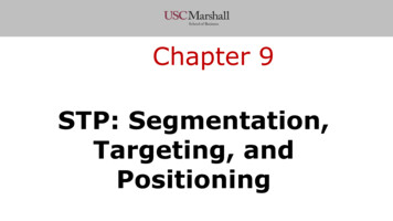
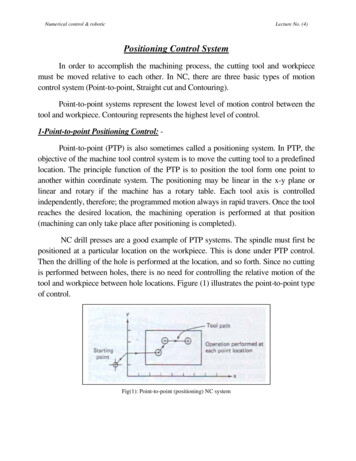
Numerical control & roboticLecture No. (4)Positioning Control SystemIn order to accomplish the machining process, the cutting tool and workpiecemust be moved relative to each other. In NC, there are three basic types of motioncontrol system (Point-to-point, Straight cut and Contouring).Point-to-point systems represent the lowest level of motion control between thetool and workpiece. Contouring represents the highest level of control.1-Point-to-point Positioning Control: Point-to-point (PTP) is also sometimes called a positioning system. In PTP, theobjective of the machine tool control system is to move the cutting tool to a predefinedlocation. The principle function of the PTP is to position the tool form one point toanother within coordinate system. The positioning may be linear in the x-y plane orlinear and rotary if the machine has a rotary table. Each tool axis is controlledindependently, therefore; the programmed motion always in rapid travers. Once the toolreaches the desired location, the machining operation is performed at that position(machining can only take place after positioning is completed).NC drill presses are a good example of PTP systems. The spindle must first bepositioned at a particular location on the workpiece. This is done under PTP control.Then the drilling of the hole is performed at the location, and so forth. Since no cuttingis performed between holes, there is no need for controlling the relative motion of thetool and workpiece between hole locations. Figure (1) illustrates the point-to-point typeof control.Fig(1): Point-to-point (positioning) NC system
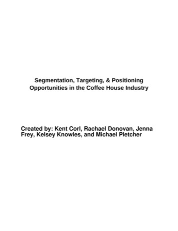
Numerical control & roboticLecture No. (4)Positioning systems are the simplest machine tool control systems and aretherefore the least expensive of the three types. However, for certain processes, such asdrilling operations, tapping, riveting and spot welding, PTP is perfectly suited to thetask and any higher level of control would be unnecessary. Example bellow illustratepath of three drilled holes.Path of three drilled holesProgrammedx25.0 y35.0x50.0 y-20.0x20.0 y30.0Tool 22-i-3Motionfromto012123Sequential: - the system will move in one axis at a time.Simultaneous: - both axes start at the same time, the tool path will be approximately.2-Straight-cut Positioning Control: Straight-cut control systems are capable of moving the cutting tool parallel toone of the major axes at a controlled rate suitable for machining. It is thereforeappropriate for performing milling operations to fabricate workpieces of rectangularconfigurations. Most of the straight-cut systems an fitted with manually adjustable feedcontrol, this feed control is shared by all the programmable axes of the NC machine,because of this shared feed control feature; the system can also perform millingoperation at 45 to the primary axes of the machine. An example of a straight cut
Numerical control & roboticLecture No. (4)operation is shown in Figure (2). An NC machine capable of straight cut movements isalso capable of PTP movements.Fig (2): Straight-cut systemExample: - the coordinate of P2 are x120mm and y60.0mm programming thesedimension would result in a tool path from 0 to 1 to P2 with the following error:Error: distance 1a 01sinα 𝑥𝑥12 𝑦𝑦12 𝑠𝑠𝑠𝑠𝑠𝑠𝑠𝑠 2𝑦𝑦12 𝑠𝑠𝑠𝑠𝑠𝑠𝑠𝑠𝛼𝛼 45 𝛽𝛽;𝛽𝛽 26.565 𝑥; 𝛼𝛼 18.435 𝐸𝐸𝐸𝐸𝐸𝐸𝐸𝐸𝐸𝐸 2𝑦𝑦 2 𝑠𝑠𝑠𝑠𝑠𝑠18.435 2 602 sin 18.435 26.8328 𝑚𝑚𝑚𝑚 ----------------too largeReducing the programmed increments to x40.0mm y20.0mm, will result the tool pathof 0 to 2 to p3.
Numerical control & roboticLecture No. (4)𝐸𝐸𝐸𝐸𝐸𝐸𝑜𝑜𝑜𝑜 2𝑦𝑦 2 𝑠𝑠𝑠𝑠𝑠𝑠18.435 2 202 sin 18.435 8.944 𝑚𝑚𝑚𝑚This value 8.944 is proportionally less, but still for too large. Reducing the programmedincrements to x0.5 y0.25.𝐸𝐸𝐸𝐸𝐸𝐸𝐸𝐸𝐸𝐸 2𝑦𝑦 2 𝑠𝑠𝑠𝑠𝑠𝑠18.435 2 0.252 sin 18.435 0.039 𝑚𝑚𝑚𝑚 . This value is efficient.In order to program tool path from point 0 to p1 in the previous example, wewould require a single tape block on a contouring system:N100 G01 x120.0 y60.00 F .Using the straight cut system, the program shown bellow will require 240 tapeblocks and will only yield a tolerance of 0.039mm.N1 . x0.50 y0.25from point (0, 0) to point (x0.5, y0.25)N2 . x0.50 y0.25to point (x1, y0.5)N1 . x0.50 y0.25to point (x1.5, y0.75)N1 . x0.50 y0.25to (x120, y60)Example: - calculate the increments to be programmed to produce the tool path withless than 0.03mm error from P1 (11.32, 9.82) to P2 (113.82, 64.32)?
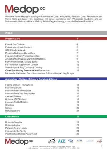
Numerical control & roboticLecture No. (4)3-Contouring (continuous) Path CNC System: Contouring is the most complex, the most flexible, and the most expensive typeof machine tool control. It is capable of performing both PTP and straight-cutoperations. In addition, the distinguishing feature of contouring NC systems is theircapacity for simultaneous control of more than one axis movement of the machine tool.The path of the cutter is continuously controlled to generate the desired geometry of theworkpiece. Contouring system generates a continuously controlled tool path by thecapability of computing the points of the path (interpolating). For this reason,contouring systems are also called continuous-path NC systems. All NC contouringsystem have the ability to perform linear and circular or parabolic interpolation featureswhich recorded in the NC computer under a (G preparatory code). Figure (3) illustratesthe versatility of continuous path NC. Milling and turning operations are commonexamples of the use of contouring control.Fig (3): contouring (continuous path) NC system for two dimensional operationsAccuracy and repeatabilityTwo of the important features of a numerical control system are its accuracy andrepeatability. The accuracy of an NC system is related to its control resolution. Theterm control resolution refers to the MCU's capability to divide the range of a givenaxis movement into closely spaced points that can be identified by the controller.If n represents the number of bits for an axis, the number of control points isgiven by
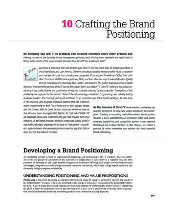
Numerical control & roboticLecture No. (4)number of control points 2nThe control resolution is therefore defined as the distance between adjacentcontrol points, and can be determined byCR range of axis movement/2nAccuracy is a measure of the control system's capacity to position the machinetable at a desired location, which is defined by a set of axis coordinate values.Accuracy (CR/2) 3 (std. dev. of mech. error)The definition of accuracy is pictured in Fig (12).Repeatability is defined in terms of the ability of the control system to return to agiven location that was previously programmed into the controller. Repeatability affectsthe capacity of the NC machine tool to produce parts that do not vary in machineddimensions from one part to the next. repeatability can define:Repeatability 3 (std. dev. of mech. error) 6 (std. dev. of mech. error)Our definition of repeatability is illustrated in Fig (12).Fig (12) Accuracy and repeatability for linear axisExample:A two-axis NC control system used as an x-y positioning table has a bit storagecapacity of 12 bits for each axis. Both x and y axes have a range of 15 in. Themechanical accuracy of the machine table can be characterized by a normal distribution
Numerical control & roboticLecture No. (4)with standard deviation 0.0003 in. for both axes. Determine (a) the control resolution,(b) the accuracy, and (c) the repeatability of the NC system.Solution:(a) The control resolution is determined byCR 15.0 in/212 15/4096 0.00366 in.(b) The accuracy is defined asAccuracy 0.00366/2 3(0.0003) 0.00273 in.(c) The repeatability, by our definition, isRepeatability 6(0.0003) 0.0018 in.Economic of NCThere are a number of reasons why NC systems are being adopted so widely bythe metalworking industry. It has been estimated that 75% of manufacturing is carriedout in lost sizes of 50 or less. As indicated above, these small lot sizes are the typicalapplications for NC. Following are the advantages of numerical control when it isutilized in these small production quantities:1-Reduced nonproduction time: - It accomplishes this decrease in nonproductivetime by means of fewer setups, less setup time, reduced workpiece handling time,automatic tool changes on some machines, and so on.2- Reduced fixturing: - NC requires simpler fixtures because the positioning isdone by the NC program rather than the fixture or jig.3- Reduced lead time: - Jobs can be set up more quickly with NC.4- Greater manufacturing flexibility: - NC adapts better to changes in jobs, production schedules, and so on.5- Easier to accommodate engineering design changes on the workpiece: -
Numerical control & roboticLecture No. (4)6- Improved accuracy and reduced human error; - NC is ideal for complicatedparts where the chances of human mistakes are high.Where is NC most appropriate?It is clear from the advantages listed above that NC is appropriate only forcertain parts, not all parts. The general characteristics of jobs for which NC is mostappropriate are the following:1-Parts are processed frequently and in small to medium lot sizes.2- Part geometry is complex.3- Close tolerances must be held on the workpart.4- Many operations must be performed on the part in its processing.5- Much metal needs to be removed (for machining applications).6- Engineering design changes are likely.7- It is an expensive part where mistakes in processing would be costly.8- Parts require 100% inspection.
Positioning Control System . In order to accomplish the machining process, the cutting tool and workpiece must be moved relative to each other. In NC, there are three basic types of motion control system (Point-to-point, Straight cut and Contouring). Point-to-point systems represent the lowest level of motion control between the tool and workpiece. Contouring represents the highest level of control.