Transcription
KEEP IN VEHICLEREAD OPERATING INSTRUCTIONSINSIDE BEFORE OPERATING PTOHINO PTO INTERFACEPTO INSTALLATIONAND OPERATOR’S MANUALFOR HINO Model Year 2015 & Laterwith Allison 2500 With CS6B-A67**-S3*H PTOMuncie Power Products, Inc.
Important Safety InformationWARNINGALWAYS READ AND UNDERSTAND THE ENTIRE MANUAL COMPLETELY BEFORE INSTALLATION OR OPERATION OF PTO ANDDRIVEN EQUIPMENT INCLUDING THESE WARNINGS AND OPERATOR’S INSTRUCTIONS IN SECTION 3!ALWAYS DISENGAGE THE PTO WHEN THE DRIVEN EQUIPMENT IS NOT IN OPERATIONDO NOT ATTEMPT TO INSTALL OR SERVICE ANY POWER TAKE--OFF WITH THE TRUCK ENGINERUNNING. PUT IGNITION KEYS IN YOUR POCKET BEFORE GETTING UNDER TRUCK.IMPORTANT SAFETY INFORMATIONDO NOT ALLOW TRUCK ENGINE TO BE STARTED WHILE WORKERS ARE UNDER TRUCK.BEFORE WORKING ON A VEHICLE PLACE TRANSMISSION IN NEUTRAL OR PARK, SET BRAKES, ANDIMMOBILIZE TRUCK WHEELS WITH SUITABLE CHOCKS.BE SURE TO BLOCK ANY RAISED BODY OR MECHANISM BEFORE WORKING ON OR UNDER EQUIPMENT.INSTALLED POWER TAKE-OFFS MUST NEVER BE SHIFTED IN OR OUT OF GEAR BY ANY MEANSEXCEPT BY THE CONTROLS IN THE CAB OF THE TRUCK.STAY CLEAR OF SPINNING DRIVESHAFTS TO AVOID BECOMING ENTANGLED AND INJURED.IT SHALL BE THE RESPONSIBILITY OF THE INSTALLER OF A MUNCIE POWER TAKE-OFF TO DECIDEWHETHER TO INSTALL GUARDS IN THE PTO AND/OR DRIVELINE AREA BECAUSE OF POTENTIALEXPOSURE TO DANGER. THIS IS BECAUSE MOST MUNCIE PTOS ARE INSTALLED BY EQUIPMENTDISTRIBUTORS OR MANUFACTURERS AND THEREFORE, THE RESPONSIBILITY OF THE INSTALLATIONIS BEYOND THE CONTROL OF MUNCIE POWER PRODUCTS.OBTAIN PROPER TRAINING BEFORE OPERATING THIS MACHINERY.DO NOT INSTALL OR OPERATE EQUIPMENT WHICH HAS NOT BEEN PROPERLY SPECIFIED FORYOUR VEHICLE.INSTALLERS ARE TO INSURE THAT PTO COMPONENTS DO NOT INTERFERE WITH ANY CHASSISCOMPONENTS, INCLUDING BUT NOT LIMITED TO VEHICLE CROSSMEMBERS, FRAME RAILS,DRIVESHAFTS, EXHAUSTS, CONVERTERS, FUEL LINES, ETC. WHILE VEHICLE IS STATIONARYOR MOBILE.ALLOW THE VEHICLE, PTO AND DRIVEN EQUIPMENT TO WARM UP WHEN OPERATING IN WEATHERWHERE TEMPERATURES ARE NEAR OR BELOW FREEZING 32 F (0 C).INSTALL SEPARATE CONTROLS FOR PTO AND DRIVEN EQUIPMENT.ALWAYS INSTALL THE SAFETY LABELS PROVIDED AND PLACE THE OPERATOR’S MANUAL IN THEVEHICLE GLOVE COMPARTMENT.The PTO is supplied with a packet containing warning labels. If you did not receive any, or if youneed extra, you may order them, no charge, by phone, email or mail. They are available throughyour nearest Muncie distributor or at the number and address below:1 -800- FOR -PTOS (1- 800- 367 -7867)Muncie Power Products, Inc.P.O. Box 548Muncie, IN 47308 -0548info@munciepower.com Muncie Power Products, Inc. 2010THIS SYMBOL WARNS OF PERSONAL INJURY OR DEATH.2
SECTION 1- PTO INSTALLATIONALL INSTALLERS MUST READ THE FOLLOWINGPTO AND ACTIVATION KITINSTALLATION INSTRUCTIONSInstall the CS6 PTO using the included IN84-03 installationinstructions. This instruction is for the electrical connections tothe Hino provided PTO connections. The PTO is provided with theappropriate harness for this connection.Always wear safety glasses. Read entire manual before starting installation.IMPORTANT: Disconnect vehicle battery prior to installingelectrical and electric/hydraulic activation kits.A. Vehicle manufacturers may have specific locations for accessingelectrical power and activating hydraulics. The body buildermanual or company repre sentative for the vehicle chassis shouldbe contacted prior to installing electri cal or hydraulic systems.B. Route wires and activation lines away from rotating and hightemperature com ponents. Use appropriate looms and bulk headpass -thru’s wherever possible to avoid rubbing through insulationor tubing and causing an electrical short or oil leak.C. Follow all Federal Motor Vehicle Safety Standards (FMVSS) foryour vehicle.D. Where electrical grounds are indicated, be sure that they are goodgrounds, with straight paths to the vehicle battery ground. (Manyvehicle cabs are insu lated from the vehicle frame and a weak groundis a very common cause for malfunctions).E. When installing hydraulic components, be certain to follow commoninstalla tion and testing procedures. If you are not familiar withacceptable installation procedures request instructions and guidancefrom the hydraulic equipment supplier.F. Caution should be taken by installer with any PTO installation to insurecompo nents do not interfere with any chassis component duringinstallation or when vehicle is operated.G. Cold weather start conditions require that the transmission be startedand warmed prior to engaging PTO and using equipment. Hydraulicpumps should be run at idle and under no load conditions to allow oilto warm before activat ing hydraulic system.3
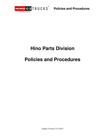
34T43770 WIRING INSTALLATION INSTRUCTIONSAlways wear safety glasses. Read entire manual before starting installation.5-wireConnector InteriorCAB HARNESSRockerSwitch PlugRelay PlugAllison Connection16-Pin5-wireConnector FrameFRAME HARNESSFrame1 wirePTO Sol.PTO Pressure Switch1. Locate the wiring harnesses provided in this kit. The harness can be separatedinto two sections. The section without the loom is for inside the cab. Pull the fuseaccess panel from the dash board.2. Remove the capscrewsholding the dash boardpanel show. Then removethis panel.4
INSTALLATION INSTRUCTIONSAlways wear safety glasses. Read entire manual before starting installation.3. The 6-WIRE Connector from Muncie Harness – Interior. This connection is thepass-through from the frame rail connection.CAN-IF CONNECTORConnector Mark: DPOWER SUPPLY CONNECTORConnector A: 16-Pin ConnectorCAB-CHASSIS THROUGHCONNECTORConnector B: 6-Pin ConnectorPTO Switch4. Using the Muncie Wire Harness, make the rocker switch connections to the Hinoharness in the cab. Push out one of the rocker switch plugs from the area nextto the steering wheel. Feed the wire harness behind the dash to this hole andconnect the rocker switch. Push the switch into position.5
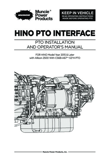
INSTALLATION INSTRUCTIONSAlways wear safety glasses. Read entire manual before starting installation.Location of 5 WIREFrame and 1-WIREFrame Connectors5-WIRE and 1-WIREConncetions5. Using the Frame half ofthe harness with the loom,locate the Hino connectoralong the right side framerail behind the cab. Removethe blank plug and connectthe Muncie Harness.CAB-CHASSIS THROUGHWIRE CONNECTORConnector Mark:EUPRRHFRLIGHTINGCONNECTORConnector Mark:GALLISON AT CONNECTORConnector Mark:HP.T.O.ACCEL SSRCONNECTORConnector Mark:F6. Route the loomed harness toward the front of the vehicle and make theconnections to the Muncie PTO activation solenoid and the pressure switch.7. Near the PTO is a Hino 16-pin connector for connection to the Allison transmissioncontrol and vehicle control. Make this 16-pin connection and cable tie thePTO harness so that it is contained to the vehicle and away from any rotatingcomponent or heat source.8. Check transmission oil level and fill with manufacturer's approved fluid, ifnecessary and run engine for 5 to 10 minutes to check for leaks, always stayingclear of rotating components.9. Complete installation by placingwarning labels as indicted on bordersof the decals. Placement examples areillustrated on page 5; turn to Section 4of Operator's Manual.After complete installation, installers need to check for leaks and proper mounting/torque of fasteners. Operate the equipment for an appropriate amount of time toestablish proper operation or per the equipment manufacturer's recommendation. Aftershutting down equipment and engine, check for leaks. Allow unit to set for 60 minutes,then check again for any leaks. Fix all leaks per manufacturer's recommendation.6
OPERATOR’SOPERATOR’SPTO Shifting Procedure& PrecautionsShifting Procedure & PrecautionsWARNINGPower Take-off Operation - Vehicle StationaryWARNING - parking brake must always be set.WARNING - vehicle’s wheels must always be chocked.WARNING - transmission must always be in neutral or park.WARNING - an operator must always be in the driver’s seat whenever the engine is running and the transmissionis in gear, in order to prevent or stop any unexpected movement of the vehicle which may causeinjuries to the operator or others in the vicinity. Read all operator’s manuals and instructions for the equipment that you are operating on this vehicle.Obtain instructions and training for all operations of the equipment on this vehicle including those not coveredby this instruction booklet.Never work alone when repairing or going under a vehicle for repair or maintenance.Always block any raised or moveable components or devices when working on or around the vehicle asspecified by the equipment manufacturer.Warning: PTOs may drive driven equipment with an exposed drive shaft which may cause severe injury ordeath if contacted.Care must be taken when using a PTO for any specific application that the PTO has been properly specifiedto match the transmission and auxiliary equipment. Improper specification and installation can cause severedamage to the vehicle transmission and the auxiliary components including driveshafts and driven equipment.Damaged components, equipment resulting in failure can cause serious personal injury to operators andpersons in the vicinity.Always follow recommended procedures for selecting, installing, operating, or repairing a power take-off asfound in Muncie operator’s manuals, service parts lists and service manuals, catalogs and application guides.Never use a Muncie PTO above the recommended operating speed of the unit or the specified driven unit.Never use a power take-off that has not been specified for the output capabilities for the equipmentbeing driven.Rotating PTO drive shaftsIt is recommended that direct couple hydraulic pumps be used whenever possible, but if your application requiresthe use of an exposed drive shaft it is the responsibility of the installer and purchaser to determine the bestinstallation of a guard. Rotating shaft can snag clothing, skin, hands, hair, etc. and will cause serious injury or death. Do not go under the vehicle when the engine is running. Do not work near an exposed drive shaft with engine running. Auxiliary shaft can be installed with recessed or protruding set screws. If raised and square head set screwsare chosen, then be aware that this is a catch point for clothes, skin, hair, hands, etc. and serious injury ordeath may result.The output shaft of a PTO with internal clutch packs may rotate in cold temperatures with the PTO disengaged.PTO shaft rotation can cause sudden movement of the output shaft and attached drive shaft leading to personalinjury or death. Allow transmission to operate for a few minutes before engaging PTO. Allow PTO to operate for afew minutes before actuating application controls.Some O.E.M. chassis manufacturers have integrated electronic controls which require certain conditions to be metbefore engaging a PTO. These include, but are not limited to setting parking brake, foot off service brake, engine atidle, foot off accelerator pedal and/or transmission selector in park or neutral.THIS SYMBOL WARNS OF PERSONAL INJURY OR DEATH7
POWER TAKE-OFF WARRANTYThe Muncie Power Take-Off is warranted to be free of defects in material orworkmanship and to meet Muncie’s standard written specifications at thetime of sale. Muncie’s obligation and liability under this warranty is expresslylimited to repairing or replacing, at Muncie’s option, within one year after dateof original installation any defective part or parts or any product not meetingthe specifications.THIS WARRANTY IS IN LIEU OF ALL OTHER WARRANTIES, EXPRESSED OR IMPLIED.MUNCIE MAKES NO WARRANTY OF MERCHANTABILITY OR OF FITNESS FOR ANYPARTICULAR PURPOSE. MUNCIE’S OBLIGATION UNDER THIS WARRANTY SHALLNOT INCLUDE ANY TRANSPORTATION CHARGES OR COSTS OF INSTALLATION ORANY LIABILITY FOR DlRECT, lNDIRECT SPECIAL, lNClDENTAL, OR CONSEQUENTIALDAMAGES OR DELAY. THE REMEDIES SET FORTH HEREIN ARE EXCLUSIVE, ANDMUNCIE’S LIABILITY WITH RESPECT TO ANY CONTRACT OR SALE OR ANYTHINGDONE IN CONNECTION THEREWITH, WHETHER IN CONTRACT, lN TORT, UNDERANY WARRANTY, OR OTHERWISE, SHALL NOT, EXCEPT AS EXPRESSLY PROVIDEDHEREIN, EXCEED THE PRICE OF THE PRODUCT OR PART ON WHICH SUCH LIABILITYIS BASED.If requested by Muncie, products or parts for which a warranty claim is made areto be returned transportation prepaid to a Muncie Service Center. Any installationor use not in accordance with catalogue or package instructions, other improperuse, operation beyond capacity, substitution of parts not approved by Muncie,use with equipment other than the equipment on which the Power Take-Off is firstinstalled, or alteration or repair made to the Power Take-Off other than at a MuncieService Center shall void this warranty. No employee or representative of Muncieis authorized to change this warranty in any way or to grant any other warranty.201 East Jackson Street Muncie, Indiana 47305800-367-7867 Fax 765-284-6991info@munciepower.com www.munciepower.comA Member of the Interpump GroupIN16-03 (Rev. 05-21)Specifications are subject to change without notice.Visit www.munciepower.com for warranties and literature.All rights reserved. Muncie Power Products, Inc. (2016)
POWER TAKE-OFF WARRANTY The Muncie Power Take-Off is warranted to be free of defects in material or workmanship and to meet Muncie's standard written specifications at the time of sale. Muncie's obligation and liability under this warranty is expressly limited to repairing or replacing, at Muncie's option, within one year after date