Transcription
Theory overview of flow measurement using differentialpressure devices based on ISO-5167 standard.Arian FL40 flow computer description.Flow Cad software users manual.Technical note 12, Differential pressure mass flow meter, rev. b, www.arian.cl1
Introduction . 31.0 Basic theory. . 41.1 Origin of differential pressure flow measurements. .41.2 ISO-5167 standard and its mass flow rate formula.72.0 The FL40 flow computer. 103.0 Arian ISO-5167 Flow Cad software. . 113.1 Software Installation.113.2 Start up. .123.3 Fluid selection. .143.4 Primary device. .183.5 Flow conditions set up. .203.6 Calculating results.223.7 Instrument parameters. .25References. 27Technical note 12, Differential pressure mass flow meter, rev. b, www.arian.cl2
IntroductionDifferential pressure flow measurement is old and reliable.With the aid of microprocessor technology now discharge coefficientcalculations can be done in real time.Even more, properties of the fluid can be stored on the instrumentand measuring temperature and absolute pressure allows to correctfluid parameters such as density and viscosity and then to obtain themass flow rate. This are called multivariable mass flow meters.By other side years of research and experiments had been doneobtaining better characterization of typical differential pressuredevices (nozzles, orifice plate , etc).The ISO5167 standard condenses all this experimental informationgiving the formulas and procedures for manufacturing a differentialpressure flow measurement device of the standard types with apredictable uncertainty.For sample calculations of ISO5167 formulas referred on thisdocument you may try our site http://www.arian.cl/ingles/flowcalc.htmlTechnical note 12, Differential pressure mass flow meter, rev. b, www.arian.cl3
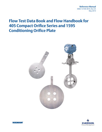
1.0 Basic theory.This overview intention is only to refresh the knowledge you alreadyhave from your technical studies. Also can be a introduction to theproblem, but reader must have some knowledge on fluid dynamics.1.1 Origin of differential pressure flow measurements.Bernoulli equation represents energy conservation for a fluid element:Const ρ g h ρυP1ρ υ 2 P2(1)Fluid DensityLinear velocity of the fluid elementPressureThe first term ρ g h is the potential energy coming from height onthe gravitational field. For our development we will suppose constantheight of our fluid, so this term is discarded and the equation is:Const 1ρ υ 2 P2(2)1ρ υ 2 is kinetic energy, here the density replaces mass.2Pressure P can be understand as a potential energy. Work is storedin compressing the fluid the same way as a compressed string storesenergy.The termWe apply this equation to a circular cross section pipe that is reducedin diameter as it goes down stream in horizontal directionTechnical note 12, Differential pressure mass flow meter, rev. b, www.arian.cl4
11ρ1 υ12 P1 ρ 2 υ 22 P222(3)ρ1 , υ1 , P1Up stream density, velocity and pressureρ 2 , υ 2 , P2Down stream density, velocity and pressureBy other side mass is conserved (not created nor destroyed) as itflows along the pipe, this is represented by the formulasQ M ρ 2 υ 2 A2 ρ1 υ1 A1(4)QMMass flow rate along the pipe, units are e.g. Kg/secA2 , A1Up and down stream cross sectional area of the pipeSquaring both sides of (4), and solving for υ 22 we haveυ 22 υ12 (ρ1 A1 2)ρ 2 A2(5)From (3), we have2 ( P1 P2 ) ρ 2 υ 22 ρ1 υ12Substituting υ 22 from (5) into this equation2 ( P1 P2 ) υ12 ( ρ 22 (ρ1 A1 2( ρ 2 ( ρ1 A1 ) 2 ρ12 ( ρ 2 A2 ) 2 )) ρ12 ) υ12 2ρ 2 A2( ρ 2 A2 ) 2From this equations, υ1 can be written asυ1 2 ( P1 P2 ) ( ρ 2 A2 ) 2( ρ 22 ( ρ1 A1 ) 2 ρ12 ( ρ 2 A2 ) 2 )This value of is substituted on (4)Technical note 12, Differential pressure mass flow meter, rev. b, www.arian.cl5
Q M ρ1 υ1 A1 2 ( P1 P2 ) ( ρ1 A1 ) 2 ( ρ 2 A2 ) 2( ρ 22 ( ρ1 A1 ) 2 ρ12 ( ρ 2 A2 ) 2 )(4a)Those who are familiar with orifice plates, will recognize the pressuredifference square root dependence of the mass flow .Now since the pipes are circular with diametersUp stream diameterDown stream diameterDdCircular cross areas aredA2 ( ) 2 π2A1 (D 2) π2Substituting on (4a) and ordering terms we obtain finallyQM with,π 2 d 2 ( P1 P2 ) ρ1ρ144( ) β )ρ21 (4b)dβ ( )DThe equation (4b) was obtained only from Bernoulli and massconservation.Is very similar to the equation (1) on page 6 of ISO 5167-1:1991(E)document, (from now on ref-1 document).In fact for a uncompressible fluid (liquid), (ρ1) 1 gets even moreρ2similar.This equation (4b) comes only from a theoric analysis, does not takeconsider turbulent flow or thermo-dynamical energy conservation forthe fluid in order to be used in a practical flow rate measurement.It is useful only to get some insight on the ISO5167 equations.Technical note 12, Differential pressure mass flow meter, rev. b, www.arian.cl6
1.2 ISO-5167 standard and its mass flow rate formula.The general equation for mass flow rate measurement used byISO5167 standard is:QM C1 β4 ε1 π 2 d 2 p ρ 14You will find it on section 5.1 of ref-1, this formula is obtained in partfrom additional complex theoric analysis but comes mostly fromexperimental research done along years and presented in severalpublications.What is interesting about ISO5167 standard is that condenses all theexperimental research and gives it in a simple and practical form (wellnot so simple but useful).We will classify the parameters on the formula by 3 different groups,this will help us understanding the formula and also on using Arianflow software.Fluid property,This are intrinsic fluid properties, e.g. density or viscosity at giventemperature or pressure.Primary device parameterThis are the primary device physical properties such as: pipediameter, bore size, device material temperature expansioncoefficient.Flow conditionsThis are the specific flow conditions, e.g., pressure, temperature ,differential pressure.QMMass flow rate, in (mass)/(time) units p Differential pressure p ( p1 p2 )Difference between the (static) pressures measured at the wallpressure tappings, one of which is on the upstream side and the otherof which is on the downstream side of a primary device (or in thethroat for a Venturi tube) inserted in a straight pipe through which flowoccurs, when any difference in height between the up-stream anddownstream tappings has been taken into account.Technical note 12, Differential pressure mass flow meter, rev. b, www.arian.cl7
ρ1Up stream fluid density.dBore diameterDPipe diameterβDiameter ratioThis is a geometric parameter of the device, that iscalculated usingdβ Dε1Expansion factor. (Up stream evaluated)Coefficient used to take into account the compressibility of the fluid.The numerical values of ε 1 for orifice plates given in ISO5167 arebased on data determined experimentally. For nozzles and Venturitubes they are based on the thermodynamic general energy equation.For liquids (uncompressible fluids), is always ε 1 1For steam and gases (compressible fluids) ε 1 1 .Is calculated with different formulas depending on the devicegeometry.For example for a orifice plate, ISO5167-1:1991(E) section 8.3.2.2gives on the following formula:ε 1 1 (0.41 0.35 β 4 ) pk p1Where k is the isentropic exponent, a “Fluid property” that dependson fluid pressure and temperature. Is related with adiabatic expansionof the fluid in the bore zone.CDischarge coefficientIs a coefficient, defined for an incompressible fluid flow, which relatesthe actual flow-rate to the theoretical flow-rate through a device.Is related with turbulent flow and the restriction the devices makes tothe flow.Again the formula for evaluating it, comes from empirical data, forexample for a orifice plate, the formula used by ISO5167-1:1991section 8.3.2.1 on page 22.Technical note 12, Differential pressure mass flow meter, rev. b, www.arian.cl8
C 0.5959 0.0312 β 2.1 0.184 β 8 0.0029 β 2.5 (10 6 0.75) 0.09 L1 β 4 (1 β 4 ) 1Re D 0.0337 L'2 β 3Where,L'2 , L1 are geometrical parameters of the orifice plate as described onsame page of the document.Re D ρ1 υ1 Dµ1is the Reynolds number for up stream flowυ1 , µ1Are the Up stream velocity and viscosity of the fluid. The viscosity isfluid property that depend on pressure and mostly on temperature.This formula for discharge coefficient is named the Stolz equation andon 1998 ISO5167 amendment, ref-2, was substituted for the largerReader-Harris/Gallagher formula (not included here because of spacelack).As you may see, this formulas are large but, there is no problemsince you will use our flow software for evaluating them with just onemouse click.You may notice that here seems to be a problem related to selfreference of the formula :You needυ1Re DCQMTo calculateRe DCQMυ1 (using density and area ofthe pipe)This problem is solved by iteration searching for self consistentresults and is done automatically by Arian Flow Cad software.Also is to be considered that the formulas given by ISO5167 havecertain validity range, depending on β , Re D values.Take a look for example at ISO5167-1 section 8.3.1.Again the Arian Flow Cad will help advising if flow conditions are outthe norm.Sample calculations of this formulas can be found on our cal note 12, Differential pressure mass flow meter, rev. b, www.arian.cl9
2.0 The FL40 flow computer.The FL40 is a powerful multivariable flow computer specifically designed for useon primary devices designed under the ISO5167 standard.Calculates actual mass flow from the 3 following parameters measuredcontinuouslydPP1T1Differential pressure input (e.g. 4-20ma, 0-10V,.)Up stream fluid pressure input (e.g. 4-20ma, 0-10V,.)Up stream fluid temperature input (Pt100, thermocouples)The fluid physical properties are stored on the FL40 so it calculates actual massflow rate or volumetric flow if you prefer.Additionally haves a 6 digit flow totalizer with alarms and communicationsfunctionalities that are described in detail in it’s user manual.Here we will concentrate on describing the input configuration for the FL40witch is done with the help of the Arian Flow Cad software.Technical note 12, Differential pressure mass flow meter, rev. b, www.arian.cl10
3.0 Arian ISO-5167 Flow Cad software.The Arian Flow Cad software is used for calculating discharge coefficient andexpansion factor as ISO5167 describes.The software generates a configuration file that is downloaded to the FL40 withthe RPS PC configuration system. So you don’t need to introduce manually alarge set of configuration parameters.Is strongly recommend to have a copy of the ISO 5167 document while youread this manual.3.1 Software Installation.You need a PC computer with-windows 95 operating system or better.-svga 800x600 color monitor.Uncompress it in any empty folder of your PC. That is all what you need to do,you are ready for start up.Since the program does not make any change on windows registry, forremoving it just delete all the files on the folder.Technical note 12, Differential pressure mass flow meter, rev. b, www.arian.cl11
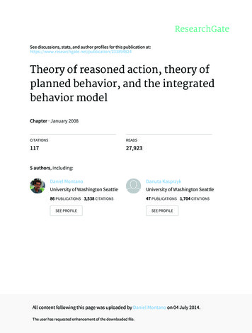
3.2 Start up.Execute application ArianIso5167FlowCad V1.exe.Within the program go to [File / Open] in the upper context menu.Open the example file air.flw as an exampleOn this main form you fill the “Flow conditions”The other forms in the context menu are the following[Fluid][Device][Notes][Instrument]Fluid properties.Primary device description and parameters.Add here comments about the project.Configuration of the FL40.Technical note 12, Differential pressure mass flow meter, rev. b, www.arian.cl12
The file menu haves the following options:[File / Open][File / Save][File / Save as][File / Report][File / Exit]Opens a new project file with extension .fldSaves the project file.Saves with different name.Generates a project report file to be printed later.In this example (air.flw) will generate air Report.txtand air Report Data.csvQuitsPress now the lower left button “Calculate” and see how calculates thecoefficients for the example.Technical note 12, Differential pressure mass flow meter, rev. b, www.arian.cl13
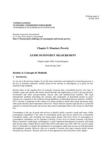
3.3 Fluid selection.The Arian Flow Cad stores about 100 common fluid properties so you simplyselect from the list the one you will use and if it is liquid or gas.The internal stored parameter allows to compute the fluid density, viscosity ,isentropic constant at operating temperature and pressure conditions.Go to the [Fluid] menu on top, the following form appears.Now you have several fluid type options:Super heated steam T, P measured.In this case you are using steam at a temperature higher than the boilingtemperature at the working pressure conditions.Is needed to measure both pressure and temperature.Properties of steam are calculated with IAPWS-IF97Saturated steam, P only measured.Upstream pressure is the same of the chamber where steam is produced.(water boiled). Th
1.2 ISO-5167 standard and its mass flow rate formula. The general equation for mass flow rate measurement used by ISO5167 standard is: 1 2 4 1 2 1 4 ρ π ε β d p C QM You will find it on section 5.1 of ref-1, this formula is obtained in part from additional complex theoric analysis but comes mostly from experimental research done along years and presented in .