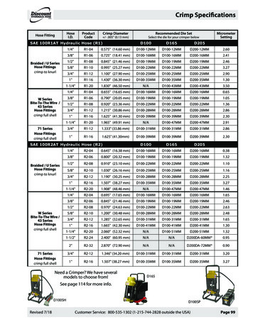
Transcription
Hydraulic and Specialty Hose Training
HYDRAULIC TERMINOLOGYSAE Society of Automotive Engineers – Standard Industry RatingsDIN German Institute for Standardization (like SAE) Deutsch Industrie NormDOT 106 (FMVSS) Department of TransportationThree types of specs:Air brake spec (J1402 Type A, A1, A2 and J844 tubing)Vacuum spec (J1403)Hydraulic spec (J1401)PSI Pounds per square inch (pressure)MPA Equivalent to 145 psiMSHA Mining Safety and Health ActUSCG United States Coast Guard (usually associated with “Coast Guard Approval” J1942)InHg Inches of mercury (vacuum) negative pressure. Return hoses with helix wire reinforcement are required to withstand 28inches of mercury vacuumGPM Gallons per minuteCubic Inches per minuteLay Line Branding of hydraulic hose to identify its characteristicsID Inside diameterOD Outside diameterPTFE Polytetrafluoroethylene (SAE 100R14 tube stock)Skive Length The length of hose cover removed for crimping couplings to a hose. This is less common with current couplingdesignsDash sizes Size of hose ID in sixteenths of an inchReduced bore hose is an exception to the rule. Refer to “How To Read Hose Part Numbers”2
HYDRAULIC TERMINOLOGY CONTINUEDTo be discussed in the future modules:JIC Joint Industrial ConferenceISO International Standards OrganizationBar Equivalent to 14.5 psiQD or QDC Quick Disconnect CouplingCouplings A connector at the end of a hoseCoupling Insert Portion of the coupling inside the hoseCoupling Ferrule Portion of a coupling crimped onto a hose coverAdapters A fitting used in conjunction with a hose couplingCrimper A hydraulic machine that deforms a metal coupling around a hose end using an eight-fingered die set3
WHAT IS A HYDRAULIC HOSE?A hose is a flexible tube used to move materials from one location to another.Hose associated with the general term “Hydraulics Hose” are constructed with a number of components:1) Tube – The layer of hose in direct contact with the hydraulic fluid. The tube must be chemically compatible with the fluid. Mosthydraulic tubes are rubber or plastic.2) Reinforcement – The layer of hose that supports the tube through normal working pressures. Reinforcement can be braidedwire, spiral wire, textile braid, or textile spiral.3) Cover – The layer of hose that protects the reinforcement layer. Hose covers can be rubber, plastic, or a rubber and textile braid.The cover must be thick enough to protect the reinforcement from abrasion and moisture, but thin enough to retain flexibility.TubeReinforcementCoverHose constructions are designed to move hydraulic fluids at normal flow rates, extreme temperatures, and abrasive conditions.The ID of the tube determines the size of the hose. Different hose constructions will vary with the wall thickness and OD.Many hydraulic hose constructions are built and tested to meet SAE, ISO, or DIN guidelines.The following illustration shows a simple hydraulic circuit. Hydraulic hose couplings and adapters connect the pump, valve, cylinder,and reservoir.Couplings will be covered in the next module.4
SIMPLE HYDRAULIC CIRCUITHydraulic FlowGaugeReservoirFilterPumpMotor5
HOSE IDENTIFICATION – LAY LINEHose SeriesDesignationWorking LotCodeCountry ofOriginHose identification is one of the many challenges when replacing a hydraulic assembly. Reference the information printedon the lay line of a hose regardless of the brand. The replacement hose should meet the industry specifications to equalthe pressure rating, temperature range, and bend radius of the previous hose.The above illustration is an example of the information found on a hose lay line.- Manufacturer Name- Hose Series designation – DR2 04- Maximum working pressure – 28 MPa (4000 PSI)- Industry designation - SAE 100R2-AT- ID of hose in millimeters and inches – 10mm (3/8”)- Date Code – MM/DD/YY- Lot Code – F-1 (Identifies the shift on a given day)- Country of Origin – Made in the USA- MSHA Mining Safety and Health Act- USCG United States Coast GuardIMPORTANT: Use the lay line as a visual indicator to avoid twisting the hose during installation. If the lay line is twisted, thehose is installed incorrectly.6
HOW TO READ HOSE PART NUMBERSHose part numbers are composed of letter(s) and numbers which identify the hose style, and a two-digit number whichdesignates the size. The two-digit number always designates the hose ID. The numerical size code follows the industrystandard “dash number” system which represents the hose ID in sixteenths of an inch.HOSE STYLEINDICATES HOSE ID*Examples:DR2-08 STYLE DR2 WITH 1/2” IDDR12X-16 STYLE DR12X WITH 1” ID* DBH, DGL, DR5, and DR14 are part of a separate dash-numberingsystem.Dash 16--20--24--32-40-48Full Bore Hose – aka Hydraulic sizes- Full bore hose has ID in 1/16 inch increments- Most hose series are built to the full bore dimensionsExamples of full bore hose: DR1, DR2, DR12, DR16 and DR171/83/161/45/163/8-1/25/83/4-1-1 1/4-1 1/2-22 .863.576.2Dash Numberfor StylesDBH, DGL, DR5, -24--32-----3/161/45/16-13/321/25/8-7/8-1 1/8-1 3/8-1 .0----Reduced Bore Hose- aka Truck sizes- Reduced bore hose has ID equal to standard steel tubing ID.- Reduced bore hose require special couplings series, or odd sizedDC couplings.7
HOW TO IDENTIFY A HOSEIdentifying a replacement assembly hose can be difficult to decipher but there are steps to help narrow down the choices,especially if the lay line is visible.1. Determine the type of equipment.2. Determine the brand of the equipment.3. Determine the Country of Origin of the equipment.4. Determine the purpose of the hose.5. Ask for the pump psi rating – or at least a reinforcement requirement.6. Identify the cover of the hose (smooth or rough).7. Identify the color of the hose (on truck applications).8. Original hose:Examine the lay line if possible.Look for SAE, DIN, or ISO specification number.Look for a part number or style type (google result).Look for Size (always keep a caliper on hand to measure the hose OD).9. Determine what type of fluid is to be transmitted (no gases).10. Identify the ID or OD (using calipers) and length of hose.11. Determine the type of reinforcement and number of wire layers or textile braids.DR12X12 / 010412XDR212 / 010212AIf there are no visible markings on the hose, examine the hose and question the customer about how the hose was used andsubsequently failed. That information could be helpful in identifying the hose.8
CHOOSING THE RIGHT REPLACEMENT HOSE-Determine pressure rating of supply pump and fluid pressures-Review Working Pressure Charts to select proper hose-Determine operating temperatures (internal and external)-Determine exposure to elements, pollutants, and environmental concerns-Examine equipment to determine any exterior flexing, abrasion, direct heat, and routing-Determine what fluid(s) are being used – petroleumMost hydraulic hose are rated for -40 F to 212 F temperatures. This is the internal oil temperature, not ambient temperature.HOW TO SELECT HOSE DIAMETERSee Flow Rate Chart on next pageGiven the flow rate in gallons per minute (gpm), or cubic inches per minutes, the customer can determine the proper hosediameter for either a pressure application or a suction application. A fluid velocity range of 10-15 feet per second is desired fora pressure application. Two to four feet per second is ideal for a suction application.Identify the gallons per minute flow rate column on the left side of the chart and the desired velocity on the right side of the chart.Apply a straight edge to the chart and to connect the points on the left and right sides. The straight edge will cross the hose IDscale in the center of the chart and identify the hose diameter called out in the center column. If the straight edge crosses atthe non-standard diameter, pick the next larger diameter.Why is this important?1. When the flow rate is very high the rapid fluid velocity can actually erode the inner tube from the hose. The damaged tubewill leak and particles of rubber will clog the pump and valve components.2. Another reason is temperature. If a fluid flows through a hose at a rate higher than 15 feet per second, enough heat can begenerated to shorten the life of the hose.9
HOW TO USE THIS CHART:Determine the proper flow rate yoursystem requires, then connect a straightedge from the selected flow rate tothe recommended velocity range. Therequired hose ID will appear at theintersection of the straight edge andthe center column. If the straight edgepasses through the scale between sizeslisted, use the next larger ID hose.Example: The flow rate your systemrequires is 10 gallons per minute. Connectyour straight edge from the 10 gallon perminute flow rate column to therecommended velocity range for pressurelines of 10 feet per second (fps). Thestraight edge intersects at 5 /8 , so therecommended hose ID is 5 /8 ”.10
PRESSURE LINES AND SUCTION LINES- Always use the middle of the recommended velocity ranges for both pressure and suction lines.- After establishing the hose diameter the next step is to select the hose series based on the working pressure andtemperature requirements.- Suction hose are rated for vacuum service in (InHg) inches of mercury. SAE 100R4 hose must be able to withstand a maximumvacuum of 28 inches of mercury and requires a helical wire in the hose carcass to prevent collapse.Refer to the Hydraulic Hose Working Pressure Chart recommending“maximum” working pressures on page 16PRESSURE CHARTHYDRAULIC HOSE 17)DBH(SAEJ61/J2064TYPEC)DB7SAE(Push- ‐On)DR5(100R5,J1402TypeAII)PremiumMulti- ‐PurposeHoseDR1(100R1)DTCDR7(FabricPush- )Multi- PWAMBHB7Y9MPTIIMXTCNR7NR7EY1n/aGSTGL IIDR14(100R14TypeA)T1014904- d30R3)DR4(100R4)DFL/DR6A6DL6U4012204- ‐012208010010- ‐010012011710- ‐011716011312- ‐011332WorkingPressures- ‐4- ‐5- ‐6- ‐8- ‐10- ‐12N/AN/AN/AN/AN/A- ‐40 to 250 F6,000N/AN/A- ‐40 to 250 F4,0004,0004,0004,000N/A- ‐40 to 212 F5,0004,0003,5002,7502,250N/A- ‐40 to 212 F5,0004,0003,5002,7502,250N/A- ‐40 to 212 F3,0003,0003,0003,0003,00004- ‐16:- ‐40 to 300 F010804A- ‐010866B20:- ‐40 to 212 F,intermittentto3,0003,0002,2502,0001,7501,500300 F012704- ‐012762- ‐40 to 212 F2,7502,5002,2502,0001,5001,250N/AN/A013504- ‐013508- ‐40 to 200 F2,7502,5002,2502,000N/A013604- ‐013658- ‐40 to 200 F2,7502,5002,2502,0001,250N/AN/AN/AN/AN/A80380- ‐80381- ‐40 to 300 F1,700030004- ‐030066- ‐40 to 300 F1,5001,5001,5001,2501,000750- ‐65 to 450 F(388 Fmaxfor014904- ns)N/AN/A012204- ‐012208- ‐40 to 212 F400400400400N/AN/AN/AN/A010010- ‐010012- ‐40 to 212 F350300N/AN/AN/AN/A011710- ‐011716- ‐40 to 212 F3003005/26/15N/AN/AN/AN/AN/A011312- ‐011332- ‐40 to 250 e- ‐4- ‐5- ‐6- ‐8- ‐10- proveduses.N/AN/AN/AN/AN/A011612- ‐011616- ‐40 to 250 F6,000N/AN/A010406X- ‐010474A- ‐40 to 250 F4,0004,0004,0004,000WorkingN/A010204A- ‐010266A- ‐40 to 212 F5,0004,0003,5002,750 Pressures2,250DaycoPartNumberTemperatureRange- ‐4- ‐5- ‐6- ‐8- ‐10- ‐12N/A011404- ‐011466A- ‐40 to 212 F5,0004,0003,5002,7502,250N/AN/AN/AN/AN/A11006- ‐40 ttoo 212 275 FF3,000N/A014704A- ‐014766- ‐40 3,0003,0003,0003,0003,000N/A80442- ‐80459- ‐22 to to257 F FN/A35035035035004- ‐16:- ‐40 300 011904- ‐011962toF ,212 F37530030030030030020:- ‐40 to- ‐40 212 intermittentto010804A- ‐010866B3,0003,0002,2502,0001,7501,50080015- ‐80040- ‐20 300 to 212 F300300300300300300F012704- ‐012762- ‐40 tFo2,7502,5002,2502,0001,5001,250- ‐40 to 200 / 212 F- ‐N/A012004- ‐012036250250250250250N/AN/A013504- ‐013508- ‐40 o 200 aFpplications)2,7502,5002,2502,00040 to 160 F(tgaseousN/A013604- ‐013658- ‐40 to 200 F2,7502,5002,2502,0001,250N/AN/AN/AN/A80372- ‐80377- ‐40 ttoo 300 212 FF225225N/AN/AN/AN/AN/A80380- ‐80381- ‐40 1,700N/A80130- ‐80135- ‐40 ttoo 300 212 FF200200200200200030004- ‐030066- ‐40 tureRange011612- ‐011616010406X- ‐010474A010204A- ‐010266A011404- ‐011466A014704A- ‐014766- ‐166,0004,0002,0002,0003,000- ‐20- ‐24- N/AN/AN/AN/AN/AN/AN/A200150100- ‐166,0004,0002,000- ‐162,000N/A3,000N/A8003001,000N/AN/AN/A- ‐20N/AN/AN/A300250- ‐24N/A- N/AN/AN/AN/AN/AN/AN/AN/AN/AN/AN/AN/AN/A- ‐20N/AN/AN/AN/AN/AN/A- ‐24N/AN/AN/AN/AN/A- ‐32N/AN/AN/AN/AN/AN/AN/ARefer to the Specialty Hose Working Pressure Chart recommending“maximum” working pressures on page 20- ‐65 to 450 F(388 Fmaxforsteamapplications)- ‐40 to 212 F- ‐40 to 212 F- ‐40 to 212 F- ‐40 to 250 50N/AN/AN/A200150100WorkingPressures- ‐10- ‐12- ‐16- ‐20- ‐24- ‐32N/AN/AN/AN/A350300N/AN/AN/AN/AN/A
Hose constructions are designed to move hydraulic fluids at normal flow rates, extreme temperatures, and abrasive conditions. The ID of the tube determines the size