Transcription
DIABLO TARPERUS Patents and Patent PendingOwner’s ManualFOR ASSISTANCECALL 252-291-2141ATTENTION DISTRIBUTOR: DO NOT DISCARD, Please forward to customerAlong with warranty registration when unit is delivered and hang driver operationTag in cab around hoist controlsWARNING: If incorrectly used, this equipment can cause injury!December 19, 20171
TABLE OF CONTENTSSection DescriptionPart 1 OperationPart 2 OverviewPart 3 Diablo Crate ContentsPart 4 Gantry InstallationPart 5 Modular InstallationPart 6 Side Arm InstallationPart 7 PlumbingPart 8 Final Adjustment & MaintenancePart 9 WarrantyPage No.23-456-78-910-1112-1617-1920COVER OPERATIONTO COVER:1.2.3.4.Rotate lower arms and extend upper arms to position the roller past the front of the container.Raise gantry to just below the container edge. (OPTIONAL)Continue to cover container.Position the roller so it will REST ON THE TOP REAR EDGE OF THE CONTAINER OR ONTHE RAILS OF THE HOIST IF HAULING A SHORT CONTAINER WHILE STAYINGBELOW 13’6”. POWER DOWN THE ROLLER AGAINST THE TAILGATE OR HOIST. Thishelps to keep the roller from bouncing up and down against the container while going down the road.If powered against the tailgate, the roller should ride tightly against the container as the truck goesdown the road.5. If over height, rotate arms until roller rests against hoist rails and power down.6. Flip the tarp side flaps down and secure them as needed.TO UNCOVER:1.2.3.4.5.Un-secure the side flapsExtend the upper arms to get roller off of container or hoist rails.Rotate the lower arms forward and clear the front top edge of the container with the roller.Lower the gantry (OPTIONAL)Rotate the lower arms and adjust the upper arms in order to position the roller down between thecontainer and the cab.6. POSITION THE ARMS SO THAT THE WEIGHT OF THE ROLLER IS RESTING ON THEBOTTOM OF THE CRADLE AND NOT ON THE ARMS! This will keep the arms from bendingdownward.***IF THE TARP ROLLER IS NOT SUPPORTED IN THE BOTTOM OF THE CRADLE, ON THEREAR OF THE CONTAINER OR ON THE RAILS OF THE HOIST, ACTUATOR AND/OR ARMDAMAGE WILL OCCUR OVER TIME RESULTING IN A BROKEN SPLINE SHAFT/ BENTARMS THAT ARE NOT COVERED BY THE TARP SYSTEM WARRANTY***2
"STE"C"4I1 ︵ ︶︵ ︶4CEAYH#EVLAVLORTNOCODPLVC#rehsaenwilkpcsolnt83 J#seiratoRotseniLleetStcennoc44︵ ︶︵ LDARC#tutNloB︵︶︵ #mrAreppUrof.lyCfodoRrofniPsivelC9PL#
"S eTEd""C i4I s1FrIeRRpOTOP4 2A0D4wA0ol46f0e44at2l4u3# g0d e8n r6a o# t︵ AmPrAAUreTpDp#UEBTT LA/D SSVLWttLA 498DO0YssD7eeHs32s8ooP23HHLM0VBFDDCOJ41#####︵ ︶︵ ︶︵ 1#&︵︶︵ fniPsivelC9PL#
DIABLO CRATE CONTENTSQuantity Part Number Name or Description2MBDMounting Brackets4SF4Gussets for Brackets2ROACRotary Actuators2LPDLinkage for Diablo2DLALower Side Arms1DTUA-DRUpper Side Arm-Drivers Side1DTUA-PAUpper Side Arm-Pass Side2DURCradle Uprights1RSA-A w/TarpRoller with Aluminum shaft & tarp attached1CRADLECradle2CD200115Upper Arm Cylinders1SAEXLPSStabilizer Bar for Diablo4JF038Steel Hydraulic Lines1HOSEKIT-DHose Kit for Diablo1SPK-DDiablo Small Parts Kit1D/TBTarp BarDIABLO-G CRATE CONTENTSQuantity Part Number Name or Description2MBDMounting Brackets4SF4Gussets for Brackets2ROACRotary Actuators2LPDLinkage for Diablo2DLALower Side Arms1DTUA-DRUpper Side Arm-Drivers Side1DTUA-PAUpper Side Arm-Pass Side2DUR-GGantry-Base2DUR-GIGantry-Insert1RSA-A w/TarpRoller with Aluminum shaft & tarp attached1CRADLECradle2CD200115Upper Arm Cylinders1SAEXLPSStabilizer Bar for Diablo4JF038Steel Hydraulic Lines1HOSEKIT-DHose Kit for Diablo1HOSEKIT-GHose Kit for Gantry1SPK-DGDiablo-G Small Parts Kit1D/TBTarp Bar1CD17548Gantry Cylinder1HPBCP-AGantry cylinder lower mount1DAGCMGantry cylinder upper mount5
FIXED GANTRY INSTALLATION1. Check for clearance between cab, exhaust, and hoist.2. You need a minimum of 8” clearance between hoist and cab to mount the gantry.3. Sit gantry (DUR) on top of chassis, remove any of the bolts that are in your way and mark themounting bracket for these holes. Drill a minimum of 2 holes in the mounting plate so that you canuse the pre-existing holes for gantry mounting. If no holes are available, new holes will need to bedrilled. If this option will not work then a chassis bridge will need to be fabricated for gantryattachment.4. The closer the roller is to the cab the easier it will be to raise and lower arms. *Note- leave aminimum of one (1”) inch clearance between cab and gantry.5. Measure the distance from hoist to gantry. Make sure both gantry legs are the same distance from thehoist and plumb.6. Position the neoprene shims on top of the gantry and place the cradle on top of the neoprene shims.Position the steel shim sandwich plates over top of the slots in the cradle and insert the 4) ½” x 1 ¾”bolts through the steel shims, cradle, neoprene shims and the gantry and secure using the ½”locknuts. The neoprene shims are there to allow for chassis flex without destroying the cradle. Besure to mount the cradle with the ½” bolts and Steel sandwich plates (HYEAC7) from the top and thelocknuts on the bottom. Do not over-torque mounting bolts and squish out the neoprene shim.Over-torqueing bolts will cause cradle to crack and void warranty. Snug bolts down until shim starts todeform into cradle slot. This should be enough torque to locate cradle to gantry7. Place roller assembly into the cradle with the end marked PASSENGER SIDE and TORQUESHAFT on the PASSENGER SIDE. Roll the tarp and tarp bar off of the top of the roller and bolt thetarp bar to the BACKSIDE of the gantry in the provided holes using the 3/8” x 5”bolts and locknuts.(See Diagram) You will need to drill the holes in the tarp bar. ( Not Pre-Drilled)8. NOTE: The shaft end on the passenger side has a FLAT spot. So you can put the supplied tensioningwheel on for tensioning.ADJUSTABLE GANTRY INSTALLATION1. Check for clearance between cab, exhaust, and hoist.2. You need a minimum of 8” clearance between hoist and cab to mount the gantry.3. Position gantry base (DUR-G) on top of chassis, remove any of the bolts that are in your way and markthe mounting bracket for these holes. Drill a minimum of 2 holes in the mounting plate so that youcan use the pre-existing holes for gantry mounting. If no holes are available, new holes will need to bedrilled. If this option will not work then a chassis bridge will need to be fabricated for gantryattachment.4. Slide the gantry inserts (DUR-GI) into the gantry base. Be sure to have the gantry tops “pointing” outto the sides versus pointing front to rear5. The closer the roller is to the cab the easier it will be to raise and lower arms. *Note- leave aminimum of one (1”) inch clearance between cab and gantry.6. Measure the distance from hoist to gantry. Make sure both gantry legs are the same distance from thehoist and plumb.7. Position the neoprene shims on top of the gantry and place the cradle on top of the neoprene shims.Position the steel shim sandwich plates over top of the slots in the cradle and insert the 4) ½” x 1 ¾”bolts through the steel shims, cradle, neoprene shims and the gantry and secure using the ½”locknuts. The neoprene shims are there to allow for chassis flex without destroying the cradle. Besure to mount the cradle with the ½” bolts and Steel sandwich plates (HYEAC7) from the top and thelocknuts on the bottom. Do not over-torque mounting bolts and squish out the neoprene shim.Over-torqueing bolts will cause cradle to crack and void warranty. Snug bolts down until shim starts todeform into cradle slot. This should be enough torque to locate cradle to gantry6
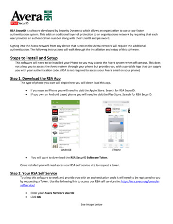
8. Measure the inside width between the gantry bases at the bottom. Then cut the gantry cylinder basemounting bracket (HPBCB-A) to width. Be sure to have the cylinder mount centered between thegantry bases.9. Install the gantry cylinder onto the base mount using the ¾” mounting pin.10. At the rod end, measure the OVERALL width of the gantry inserts. Cut the gantry cylinder uppermounting bracket (Part# DAGCM) to this width. Be sure to keep the mounting clevis in the center11. Slide the gantry cylinder upper mounting bracket onto the gantry inserts and then slid down onto thegantry cylinder rod mount. Install the ¾” pin attaching the cylinder to the mount.12. Be sure that the upper and lower cylinder mounts are square and plum. Firmly weld in the mounts13. Place roller assembly into the cradle with the end marked PASSENGER SIDE and TORQUESHAFT on the PASSENGER SIDE. Roll the tarp and tarp bar off of the roller and bolt the tarp barto the BACKSIDE of the gantry in the provided holes using the 3/8” x 5”bolts and locknuts. (SeeDiagram) You will need to drill the holes in the tarp bar. ( Not Pre-Drilled)14. NOTE: The shaft end on the passenger side has a FLAT spot. So you can put the supplied wrench onfor tensioning.Cradle w/roller assem bly1/2" Bolt and sandwichplate (Part# HYAE-C7)12" locknutNeoprene Shim (Part# HYAEC4)G antryTarp and Tarp BarM ounted 12" below cradleusing 3/8"x5" bolt,washer,& nut7
PIVOT POINT INSTALLATIONNOTE: The installation of the Diablo pivot is very simple. The only thing involved is mounting the rotaryactuators to the truck’s chassis1. Federal D.O.T. allows for 108” overall width for safety devices. Therefore; maximum width for the DiabloTarper must not exceed 108” overall width. This includes any bolts, nuts, hydraulic fittings, etc. Checkwith your state and local D.O.T. to determine what standards apply in your area!2. For example, if the hoist is 35 ½” wide, then the following formula will give you your maximum overallwidth, if it is agreeable with your local D.O.T.3. 108”-35-1/2” 72-1/2”4. 72-1/2” divided by 2 36-1/4” maximum width from hoist for each side. O’Brian’s recommendation wouldbe 36”maximum width for each side in this scenario to allow for “deviations” in DOT measurement devices5. PIVOT POINT LOCATION: Due to the rotary actuator’s width, a standard pivot point location will notwork. But due to the actuators 180 degree capability, we can mount the actuator in a better, more ideallocation. You can place it in front of the first drive wheel, if that is close to center6. The Rotary Actuators are not side sensitive; however the splines are located in mid-rotation and need to berotated all the way to the front of the truck before sliding on or torqueing down the linkage assembly to thespline adapter. The actuators must be square side-to-side, and parallel to the hoist. They must be set up sothat the arms will fall into the cradle and not stop just before it. If a slanted installation is needed tocompliment the fender profile, then mount the actuators in 60 degree increments and allowfor the roller to completely fall into and be supported by the cradle!!Due to the splines of the actuator, the actuator MUST be mounted in 60 degree incrementsto allow for the upper arm to run perpendicular to the ground and to allow for enougharm rotation to cover a 22’ 40 cu. yd. box7. As a general rule, mount the actuators as low as possible to clear the container8. Use the supplied 3” x 3” tubing for mounting the actuator. You may have to cut the length to get theactuator out to but not past 108”. DO NOT WELD TO THE CHASSIS!! THERE MUST BE APLATE BOLTED TO THE CHASSIS AND/OR USE THE HOIST MOUNT TO WELD TO.8
9. Before the tubing has been welded, you must orient the actuator mounting plate. This is the 7”x7”x1/2”metal plate with 4- ¾” holes in it. Be sure to orient the plate CORRECTLY with the actuator as the ¾”holes are NOT in a perfect square. Tack-weld the mounting bracket in place and mount the actuatorwith the ¾” bolts and lock washers. Check for clearance between tires, containers, etc. Once you aresure of the installation, burn in the welds, add the gussets under and beside the tubing, and torque the¾” bolts to 150 ft/lbs.NOTE: Gussets must be welded under and to the side of the tubing to give vertical, lateraland torsional support to the actuator mounting bracket(s).Actuator Mounting PlateAlign holes of mounting bracketwith actuator before weldingmounting bracket to truckHoles are NOT squareInstall threadlocker & snugdown 3/8" x1 21" grade 8 boltagainst large 41" thick washerwith spacer & torque
DIABLO TARPER US Patents and Patent Pending Owner’s Manual FOR ASSISTANCE CALL 252-291-2141 ATTENTION DISTRIBUTOR: DO NOT DISCARD, Please forward to customer Along with warranty registration when unit is delivered and hang driver operation Tag in cab around hoist controls WARNING: If incorrectly used, this equipment can cause injury! December 19, 2017 . 2 TABLE OF