Transcription
PLC Connection GuideSiemens S7-200 PPISupported Series: Siemens S7-200 series te: http://www.siemens.com/entry/cc/en/HMI Setting:ParametersRecommendedOptionsNotesPLC typeSIEMENS S7-200 PPIPLC I/FRS485 2wRS485 2wBaud rate96009600, 19200, 187.5KData bits87,8ParityEvenEven, Odd, NoneStop bits11, 2Turn around delay5ACK delay time (ms)30PLC sta. no.2Only MT6000/8000V2 supportbaud rate 187.5 K1 126Online simulatorYESBroadcast commandNOExtend address modeYESPLC Setting:PLC settingPLC sta. no. can not be the same as HMI sta. no.Device Address:Bit/WordDevice typeFormatRangeMemoBIDDDDo0 40957Input (I)BQDDDDo0 40957Output (O)BMDDDDo0 40957Bit MemoryBVW BitDDDDDo0 102397V Memory Bit AddressBSDDDDo0 40957SCRBSMDDDDo0 40957Special MemoryBT BitDDD0 255TimerBC BitDDD0 255CounterByteVBDDDDD0 10239
PLC Connection GuideBit/WordDevice typeFormatRangeMemoWVWDDDDD0 10239V MemoryWVW OddDDDDD0 10239V MemoryDWVDDDDDD0 10239V Memory Double WordDWVD OddDDDDD0 10239V Memory Double WordWVW StringDDDDD0 10239StringWVW String Odd DDDDD0 10239StringDWVD StringDDDDD0 10239StringDWVD String OddDDDDD0 10239StringByteMBDDDDD0 10239Byte MemoryWMWDDDDD0 10239Word MemoryWMW OddDDDDD0 10239Word MemoryWTDDD0 255TimerWCDDD0 255CounterDWMDDDDDD0 10239Word MemoryByteSBDDDDD0 10239SCRWSWDDDDD0 10239SCRDWSDDDDDD0 10239SCRByteSMBDDDDD0 10239Special MemoryWSMWDDDDD0 10239Special MemoryDWSMDDDDDD0 10239Special Memory Double Word and floating point value must use VD device type.Multi-HMIs-Multi-PLCs Communication Setting:
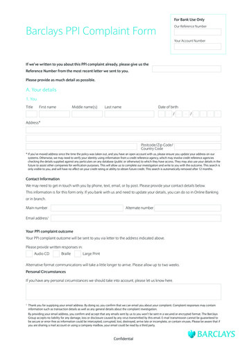
PLC Connection GuideFor S7-200 PLC, Multi-HMIs-Multi-PLCs communication can be achieved using S7/200PPI driver, please refer to the settings below.IN EasyBuilder COM Port Settings, two important parameters must be set:1. [High station address (HSA)]:Setting Max. Station Number of HMI in PPI network.For the effectiveness of system operation, it is highly recommended that the HMI stationnumber starts from zero and go on sequentially. If there are 4 HMI in PPI network, setstation no. from 0 3, and [High station address (HSA)] to 3.Set HMI station number in [System Parameters] / [Model] / [HMI station no.]:2. [Gap update factor(GUF)]:The condition to pass a Token. In PPI network only HMI can hold a Token, PLC can onlybe controlled.When the HMI that holds Token communicates with PLC for a number of times that equalsto the value set here, HMI will pass the Token (control of PLC) to the next HMI. Forexample, if GUF is set to “1”, HMI will pass the control of PLC to the next HMI when reador write the value in an address.
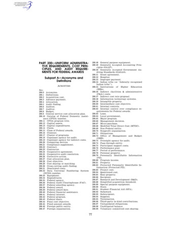
PLC Connection GuideIf GUF is set to a bigger value, the HMI that holds Token will control the PLC for a longertime and therefore the Token won’t be passed to another HMI and cause failure incommunicating with PLC.A complete communication means HMI reads / writes PLC value for one time.Note: HMI sta. no. can not be the same as PLC sta. no.Highly recommended that HMI sta. no. starts from 0 and go on sequentially for theeffectiveness of operation.Available for EasyBuilder V4.50 and later.How to Import Tag:The tags created in the Symbol Table in Step7-MicroWIN software can be imported toEasyBuilder.1. In Symbol Table create the tags. Select all the tags and click the right mouse buttonthen copy the tags.2. Launch EasyBuilder, add the driver in the device list in System Parameter Settings,and then click Import Tag button.
PLC Connection Guide3. Paste the tags copied in step 1 and then click OK.4. Select all the tags and then click OK.5. If succeeded, the following message window shows.
PLC Connection GuidePass-Through Settings:[Designate client IP]: In Pass-through mode designate the client IP address to connectHMI. The “client” usually refers to Siemens Step 7 application.The following lists the system registers relevant to Siemens S7-200 PPI andSiemens S7-300 MPI Pass-through feature. [LW-10850: disable/enable (0 : disable, 1 : normal, 2 : IP limited) (siemenspass-through)] [LW-10851: destination COM port (siemens pass-through)]: Generally refers to theCOM port connected with PLC. [LW-10852: destination PLC station no. (siemens pass-through)][LW-10853: communication protocol (0 : invalid, 1 : PPI, 2 : MPI) (siemenspass-through)][LW-10854 to LW-10857: IP of connecting client (siemens pass-through)]: Displays current client IP address connected with HMI.[LW-10858 to LW-10861: IP of designated client (siemens pass-through)]: IfLW-10850 is set to 1, the system registers can be used to designate the client IPconnected with HMI.[LW-10862: connection status (0 : ready, 1 : client connecting) (siemens pass-through)][LW-10863: execution status (0 : normal, 1 : error) (siemens pass-through)][LW-10864: the last error (siemens pass-through)]
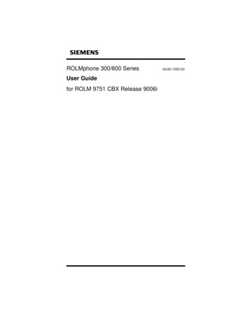
PLC Connection GuideThe following table lists the error codes, the description of each code, and thepossible reason.Error CodeDescriptionPossible Reason0Successfully executed1Prohibit client from connecting HMI is already running pass-throughHMIand won’t accept any request fromother client.2Prohibit client from connecting When LW-10850 is set to 1, theHMIclient IP for connecting HMI isdifferent from the IP specified inLW-10858 LW-10861.3Invalid communicationInvalid setting in LW-10853.protocol4Invalid PLC station numberThe PLC station number specified inLW-10852 does not exist.5Delayed communicationPLC connection failure.6Busy communicationPLC does not accept pass-throughrequest, please confirm PLCsettings.7Invalid pass-through requestEnvironment setup failure.Wiring Diagram:Diagram 1cMT SeriescMT3151eMT SerieseMT3070/ eMT3105 / eMT3120 / eMT3150HMIPLCCOM1COM3RS485 2W9P MaleRS485 2W9P MaleRS485 2W9P D-SubMaleData-168 Data-Data 293 Data GND555 GND
PLC Connection GuideDiagram 2cMT SeriescMT-SVR / cMT-G01 / cMT-G02 / cMT-HDM / cMT-FHDmTVmTVHMIPLCCOM2COM3RS485 2W9P FemaleRS485 2W9P FemaleRS485 2W9P D-SubMaleData-748 Data-Data 613 Data GND555 GNDDiagram 3MT-iEMT8070iE / MT6070iE / MT8100iE / MT8121iE / MT8150iEMT-XEMT8121XE / MT8150XEHMIPLCCOM1COM3RS485 2W9P MaleRS485 2W9P MaleRS485 2W9P D-SubMaleData-178 Data-Data 283 Data GND595 GNDDiagram 4cMT SeriescMT3071 / cMT3072 / cMT3090 / cMT3103MT-iEMT8071iE / MT6071iE / MT8072iE / MT6072iE / MT8073iE /MT8101iE / MT8102iE / MT8103iEMT-XEMT8090XE / MT8092XEMT-iPMT6103iP / MT8102iP
PLC Connection GuideHMIPLCCOM2COM3RS485 2W9P MaleRS485 2W9P MaleRS485 2W9P D-SubMaleData-168 Data-Data 293 Data GND555 GNDDiagram 5MT-iEMT8050iE / MT8053iEMT-iPMT6051iP / MT8051iPHMIPLCCOM1COM3RS485 2W9P FemaleRS485 2W9P FemaleRS485 2W9P D-SubMaleData-178 Data-Data 283 Data GND555 GNDDiagram 6MT6071iP / MT8071iPMT-iPHMIPLCCOM2RS485 2W9P FemaleRS485 2W9P D-SubMaleData-18 Data-Data 23 Data GND55 GND
The tags created in the Symbol Table in Step7-MicroWIN software can be imported to EasyBuilder. 1. In Symbol Table create the tags. Select all the tags and click the right mouse button . The "client" usually refers to Siemens Step 7 application. The following lists the system registers relevant to Siemens S7-200 PPI and Siemens S7-300 MPI .