Transcription
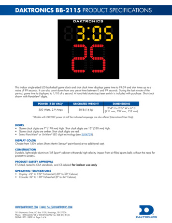
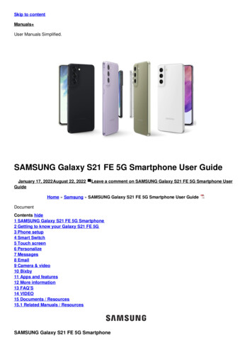
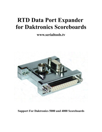
Skip to contentManuals User Manuals Simplified.DAKTRONICS Large Matrix Galaxy GS6 Series 19.8mmMonochrome Message Displays Installation GuideApril 7, 2022April 10, 2022 Leave a comment on DAKTRONICS Large Matrix Galaxy GS6 Series 19.8mmMonochrome Message Displays Installation GuideHome » DAKTRONICS » DAKTRONICS Large Matrix Galaxy GS6 Series 19.8mm Monochrome MessageDisplays Installation GuideLarge Matrix Galaxy GS6 and GT6X SeriesInstallation Quick GuideContents hide1 Mount Display2 Connect Power3 External Cable Installation4 Communications Installation5 Documents / Resources5.1 References5.2 Related Manuals / ResourcesMount DisplayFor Multi-Section Displays – See Section Splice Instructions (p.3).1. Lift the display into position on the support structure.Refer to the label at lift eyes for information. Maintain a 55-degree or greater angle between the display and lift straps. Do not adjust or remove lift eyes. Do not lift display in wind speeds greater than 20 mph.
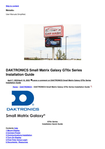
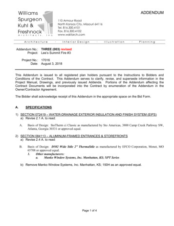
2. Weld or bolt ALL T-clips to support structure.Note: T-clips can be adjusted within the guidelines specified in the Shop Drawing.Connect PowerNote: GT6X displays have multiple power entrances depending upon the display length.1. Route conduit from the main distribution panel/disconnect to each display power entrance. In GT6X displays,each display section has a power entrance and requires adedicated circuit2. Remove the four screws that attach to the power entrance access door.3. Connect conduit to the 11 /4 ″ Myers hub at the left of the power entrance box.4. Feed the power cable from the conduit into the power entrance box.5. Connect primary power lines to appropriate taps in the enclosure – refer to the label on the enclosure for thewiring diagram.
6. Reinstall the power entrance cover.7. Connect grounding electrode to the ground lug on each section.External Cable InstallationRefer to the label on the back of the display for cable routing.1. Install fiber quick-connect cables between display sections when applicable.2. Install fiber quick-connect cable between Primary and Mirror display faces when applicable.
Note: Remove the protective cap from the cables.Communications InstallationMount display communications enclosure (wired Ethernet, fiber Ethernet, or radio) according to guidelines in thecommunications manual.1. Route quick-connect cables from enclosure to Primary display quick connect.2. Connect cables to quick-connect on back of the display.Make interior connections to the customer’s network or directly to the control computer.Turn Display On1. Turn on power to the display.2. Observe the boot sequence shown on the display to get the IP Address or DHCP name. The boot time lastsabout three minutes. Displays are set to DHCP from the factory. If a static IP address is required, contact theDaktronics Help Desk at 800-325-8766.First-Time Venus LoginLogging In – Daktronics Hosted Server1. Navigate to https://venus.daktronics.com using a web browser such as Internet Explorer version 11 or lateror Chrome.2. Enter the user name and password into the Email and Password text boxes.
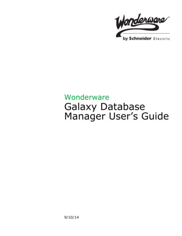
3. Change the password in the Update Password text boxes.4. Update the account information in the User Information and Additional Information sections.Log In – Customer-Local Hosted ServerNavigate to https://ComputerName:44300 (entering the actual computer name for ComputerName).Venus AssistanceFor further assistance, contact Daktronics Customer Service.U.S. and Canada: 1-800-DAKTRON (1-800-3258766)Outside the U.S. and Canada: 1-605-697-4000 Onlinehttp://www.daktronics.comSection Splice InstructionsDue to size, some displays ship in multiple sections.A sectional display consists of multiple sections to form a single display face.Section splicing can be completed at ground level if the display is no more than two sections tall.1. Ensure the splice key is in the channel on the bottom section.2.3.4.5.6.Attach crane to top section.Unbolt the top section from the truck.Lift the top section and spin 180 degrees.Lower top section until splice key engages.Use a splice wrench to draw sections together.
7. Connect splice plates and splice T-clips to both sections.8. Tighten all nuts on all splice plates and splice T-clips.9. Refer to Step 1 in Mount Display (p.1).201 Daktronics DriveBrookings, SD cuments / ResourcesDAKTRONICS Large Matrix Galaxy GS6 Series 19.8mm Monochrome Message Displays [pdf]Installation GuideLarge Matrix Galaxy GS6 Series, 19.8mm Monochrome Message Displays, Large Matrix GalaxyGS6 Series 19.8mm Monochrome Message Displays, GT6X SeriesReferencesDaktronics :: Scoreboards, LED Video Displays, Message Signs, BillboardsVenus Log InRelated Manuals / ResourcesDAKTRONICS Small Matrix Galaxy GT6x Series Installation GuideGT6x Series Installation Quick Guide Mount Display Lift the display intoposition on the support structure. Weld or SHARP NEC MultiSync MA Series Large Format Displays User ManualNEC MultiSync MA Series Large Format Displays 43", 49" and 55" Commercial Displays Ideal for DigitalSignage
NEC ME Series MultiSync Large Format Installation GuideNEC ME Series MultiSync Large Format Installation Guide [Ver.1.1] ProductDescription Type: LCD Display Resolution: 3840 x 2160 DAKTRONICS DXB Series Digital Billboard Installation GuideDXB Series Digital Billboard Installation Quick Guide Time-Saving TipsLocate installation parts and tools in the box shipped Leave a commentYour email address will not be published.CommentNameEmailWebsiteSave my name, email, and website in this browser for the next time I comment.Post CommentManuals ,homeprivacy
DAKTRONICS Large Matrix Galaxy GS6 Series 19.8mm Monochrome Message Displays Installation Guide April 7, 2022April 10, 2022 Leave a comment on DAKTRONICS Large Matrix Galaxy GS6 Series 19.8mm . communications manual. 1. Route quick-connect cables from enclosure to Primary display quick connect. 2. Connect cables to quick-connect on back of .