Transcription
ALL SPORT 5500 SERIESCONTROL CONSOLEOPERATION MANUALP1389ED-16809Rev 99 February 2018201 Daktronics DriveBrookings, SD 57006-5128www.daktronics.com/support800.325.8766
Copyright 2006-2018All rights reserved. While every precaution has been taken in the preparation of this manual, the publisher assumes noresponsibility for errors or omissions. No part of this book covered by the copyrights hereon may be reproduced or copiedin any form or by any means—graphic, electronic, or mechanical, including photocopying, taping, or informationstorage and retrieval systems—without written permission of the publisher.Daktronics trademarks are property of Daktronics, Inc. All other trademarks are property of their respective companies.
Table of Contents1Introduction 1General Multi-Purpose Timer 18Important Safeguards 1Standard Keys 18Specifications Label 2Segment Timer 18Resources 2Team Name Entry 19Console Revision History 2WIDTH 19Daktronics Exchange and Repair &Return Programs 2HEIGHT 19Exchange Program 2Repair & Return Program 3FONT 193Segment Timer Overview 20Daktronics Warranty & Limitation ofLiability 32Accessing Segment Timer 20Accessing 2-Digit or 6-Digit DisplaySegment Timer 21Basic Operation 4Console Operation 4Segment Timer Keys 21Sport Inserts 5Segment Number & Time 21Start Up 6First Segment 21Standard Keys 6Last Segment 22Start 6Interval Time 22Stop 6Display Interval 22Enter/Yes 6Copy Range 22Clear/No 7Auto Stop 23Edit 7Reset to First 23Menu 7Reset Current Segment 23Set Main Clock 7Current Segment 23Count Up/Down 8Edit 23Auto Horn 9Current Segment 23Manual Horn 9Menu 23Remote Start/Stop Controls 9New Code 24Main Clock Control 9Warning Time 24Shot Clock Control 9Dimming Menu 24Setting Radio Channels 10Single Controller System 11Multiple Controller System with SingleBroadcast Group 12Segment Timer Operation 20Default Settings 244Basketball Operation 25Basketball Keys 25Set Shot Time 25Multiple Controller with MultipleBroadcast Groups 13Recall Shot Time 26Time Out On/Off 26Menu 14Blank Player Foul 26New Game 14Period 1 27New Code 15Time Out 27Dimming Menu 15Score ( 1/ 2/ 3/-1) 27Display Menu 15Team Fouls ( 1/-1) 28Color Menu 16Bonus 29Time of Day 17Possession 29Switch Output 18–i–
Table of ContentsIn Game/Out of Game 29In Game/Out of Game 43Delete Player 29Delete Player 43Player 29Player 43Individual Substitution 30Individual Substitution 44Mass Substitution 31Mass Substitution 45Edit 31Edit 45Time Out 31Time Out 45Score ( 1/ 2/ 3/-1) 32Score ( 1/-1) 46Team Fouls ( 1/-1) 32Match Number 1, Sets 1 46Period 1 32Sets Won 1, Subs 1 46Time Out On/Off 32Aces 1, Kills 1, Blocks 1, Digs 1 46Menu 33Time Out On/Off 46New Game 33Menu 47New Code 33New Game 47Dimming Menu 33New Code 47Home Roster, Guest Roster 33Dimming Menu 47Display Menu 34Home Roster, Guest Roster 47Color Menu 34Display Menu 49Time of Day 34Color Menu 49Edit Settings 35Time of Day 49Number of Periods 35Edit Settings 49Main Clock 35Main Clock 49Shot Clock 36Time Outs 49Time Outs 36Team Stats 50Team Score 37User Def 1 & User Def 2 50Team Fouls 37Select Captions 51Select Captions 38Shot Horn Control 51Select Team Foul Display 38Light Control 51Score by Quarter 38Switch Output 51Shot Horn Control 38Default Settings 52Light Control 38Switch Output 3956Wrestling Operation 53Wrestling Keys 53Default Settings 39Match Number 1 53Volleyball Operation 40Period 1 53Volleyball Keys 40Set Main Clock (Period Times) 54Time Out On/Off 40Home Advantage, Guest Advantage,Stop Advantage Clock 54Time Out 41Team Score ( 1/-1) 55Match Number 1, Sets 1 41Match Score ( 1/ 2/ 3/-1) 55Score ( 1/-1) 41Start/Stop Injury Time 55Sets Won 1, Subs 1 42Reset Match 56Aces 1, Kills 1, Blocks 1, Digs 1 42Start/Stop Blood Time 56Serve 42– ii –
Table of ContentsStart/Stop Recovery Time 57Edit 57Home Advantage 57Guest Advantage 57Blood Time 58Injury Time 58Match Number, Period, Team Score,Match Score 58Menu 58New Game 58New Code 58Dimming Menu 59Home Roster, Guest Roster 59Weight Class 60Display Menu 60Color Menu 60Time of Day 60Edit Settings 60Main Clock 60Blood/Injury Time 61Recovery Time 61Select Captions 62Weight Class 62Display Lines for Weight Class 62Display Team Score 62Shot Horn Control 62Light Control 63Switch Output 63Default Settings 63A Reference Drawings 65BSport Inserts 77C Sport Code Numbers 85D Quick Reference 87All Sport 5500 Standard Keys 87Segment Timer 88Basketball 89Volleyball 90Wrestling 91ESupplementary Documents 93FDaktronics Warranty and Limitationof Liability 99– iii –
This page intentionally left blank.
1IntroductionThis manual explains the operation of All Sport 5500 series control consoles. Foradditional information regarding the safety, installation, operation, or service of thissystem, refer to the telephone numbers listed in Daktronics Exchange and Repair & ReturnPrograms (p. 2).Important Safeguards Read and understand all instructions, both general and for specific sports. Always turn off and/or unplug the control equipment when it is not in use. Never yankthe power cord to pull the plug from the outlet. Grasp the plug and pull to disconnect. Do not drop the control console or allow it to get wet. This device shall not be exposed to dripping or splashing, and no objects filled withliquid shall be placed upon it.WARNING! To reduce the risk of fire or electric shock, do not expose this device torain or moisture. Console may include internal battery backup, or external battery pack.CAUTION! DANGER OF EXPLOSION IF BATTERY IS INCORRECTLY REPLACED.REPLACE ONLY WITH THE SAME OR EQUIVALENT TYPE.WARNING! Do not expose batteries to excessive heat, such as direct sunlight or fire. Do not let the power cord touch hot surfaces or hang over the edge of a table thatwould damage or cut the cord. If an extension cord is necessary, use a three-pronged, polarized cord. Arrange thecord with care so that it will not be tripped over or pulled out. Before using an extension cord, inspect the cable thoroughly and verify itscompliance with the local electric codes. Do not disassemble control equipment or electronic controls of the display; failure tofollow this safeguard will make the warranty null and void. Inspect console for shipping damage such as rattles and dents, and verify that allequipment is included as itemized on the packing slip. Immediately report anyproblems to Daktronics; save all packing materials if exchange is necessary.All Sport consoles receive external power through a standard 8’ (2.44 m) long threepronged power cord plugged into a 120 VAC grounded outlet. The outlet shall beinstalled near the console and easily accessible. Contact Daktronics for information onrunning an All Sport console via optional battery power pack.Note: The console features an internal time delay 1/8 amp, 250 V fuse. In the unlikelyevent the fuse needs to be replaced, contact Daktronics Customer Service.Introduction1
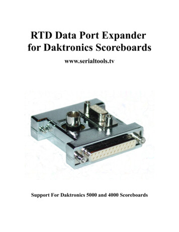
Specifications LabelPower specifications as well as product assembly information can be found on the rearof the console. When calling Daktronics customer service, please have the assemblynumber and the date manufactured available to ensure the request is serviced asquickly as possible.ResourcesFigure 1 illustrates a Daktronics drawinglabel. This manual refers to drawings bylisting the last set of digits. In the example,the drawing would be referred to asDWG-1007804. All references to drawingnumbers, appendices, figures, or othermanuals are presented in bold typeface.Any drawings referenced in a particularsection are listed at the beginning of it asshown below:Drawing NumberFigure 1: Drawing LabelReference Drawing:System Riser Diagram. DWG-1007804Daktronics identifies manuals by the DD or ED number located on the cover page.Console Revision HistoryFor a complete history of revisions to the console firmware, refer to All Sport & OmniSportRevision Histories (DD3679410), available online at www.daktronics.com/manuals.Daktronics Exchange and Repair & Return ProgramsExchange ProgramThe Daktronics Exchange Program is a service for quickly replacing key componentsin need of repair. If a component fails, Daktronics sends a replacement part to thecustomer who, in turn, returns the failed component to Daktronics. This decreasesequipment downtime. Customers who follow the program guidelines explained belowwill receive this service.Before contacting Daktronics, identify these important numbers:Assembly Number:Job/Contract Number:Date Manufactured/Installed:Daktronics Customer ID Number:To participate in the Exchange Program, follow these steps:1. Call Daktronics Customer Service.Market DescriptionCustomer Service NumberSchools (including community/junior colleges), religiousorganizations, municipal clubs, and community centers877-605-1115Fax: 605-697-4444Universities and professional sporting events, live events forauditoriums, and arenas866-343-6018Fax: 605-697-4444Introduction2
2. When the new exchange part is received, mail the old part to Daktronics.If the replacement part fixes the problem, send in the problem part being replaced.a. Package the old part in the same shipping materials in which the replacementpart arrived.b. Fill out and attach the enclosed UPS shipping document.c. Ship the part to Daktronics.3. The defective or unused parts must be returned to Daktronics within 5 weeks of initialorder shipment.If any part is not returned within five (5) weeks, a non-refundable invoice will bepresented to the customer for the costs of replenishing the exchange parts inventorywith a new part. Daktronics reserves the right to refuse parts that have beendamaged due to acts of nature or causes other than normal wear and tear.Repair & Return ProgramFor items not subject to exchange, Daktronics offers a Repair & Return Program. To senda part for repair, follow these steps:1. Call or fax Daktronics Customer Service.Refer to the appropriate number in the chart on the previous page.2. Receive a case number before shipping.This expedites repair of the part.3. Package and pad the item carefully to prevent damage during shipment.Electronic components, such as printed circuit boards, should be placed in anantistatic bag before boxing. Daktronics does not recommend using packingpeanuts when shipping.4. Enclose: name address phone number the case number a clear description of symptoms5. Ship to:Daktronics Customer Service[Case #]201 Daktronics Drive, Dock EBrookings, SD 57006Daktronics Warranty & Limitation of LiabilityThe Daktronics Warranty & Limitation of Liability is located at the end of this manual. TheWarranty is independent of Extended Service agreements and is the authority in mattersof service, repair, and display operation.Introduction3
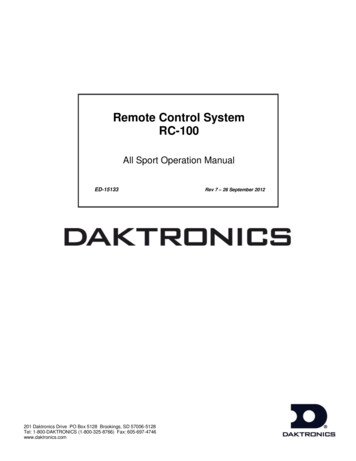
2HornControlBasic OperationClockControlConsole OperationThe console face consists of a 2-line by 16-character liquid crystal display (LCD), number/NumberMenuSport-Specific Insertmenu keypads,horn/clockcontrols with LED statusindicators,and an area for a sportKeypadNavigationspecific insert. Refer to Figure 2 to locate these components on the control console face.LCDHornControlClockControlSport-Specific InsertNumberKeypadMenuNavigationFigure 2: All Sport 5500 LayoutIn most cases, the top line of the LCD shows the main clock time, direction the clock isLCDcounting, and when the main horn is sounding, while the bottom line typically shows theHOME and GUEST team scores.The standard fixed keys and functions on the right side of the console are explained inStandard Keys (p. 6). All of the keys that pertain to a specific sport code insert areexplained in detail in their respective sport section.In addition, Quick References and Menu Flowcharts for the Standard Keys and many ofthe more common individual sports are provided in Appendix D.Throughout this manual, the names or letters of keys on the keypad are enclosed inangle brackets (such as ENTER ).Sport-Specific InsertLCDBasic Operation4
Sport InsertsSport inserts allow one console to control multiple sports. Select the proper insert from thechart below and slide it into the insert opening on the left side of the console until it stops.To remove a sport insert, pull on the tab that extends from the left side of the console.If an insert is lost or damaged, a printed copy of the insert drawing from Appendix B maybe used until a replacement can be ordered. Print this page (if viewing digital copy) andwrite the code number in the following table for all applicable sports.If the code number for a scoreboard is unknown, refer to Appendix C. If the modelnumber of a scoreboard is unknown, refer to the documentation provided with thescoreboard.SportInsert NumberBasketballLL-2433Segment r CodeNot applicableA sport insert identifies the keys required for normal operation of a specific sport. In mostcases, pressing a key immediately changes the scoreboard. Keys that require entryof additional information are marked by a dot. This additional information is usually anumber followed by the ENTER key.Keys with arrows activate an indicator (possession, bonus, etc.) on the scoreboard. Thedirection of the arrow selects the appropriate team (home or guest).Some keys are labeled 1, 2, or 3. By pressing one of these keys once, thecorresponding field on the scoreboard (such as score or period) “increments”, orincreases, by the amount printed on the key. A key with -1 “decrements”, or decreases,by one.On most inserts, certain keys have been grouped together under the heading Homeor Guest. These keys are team keys and work the same for both teams. They affect thestatistics only for that one team. Keys not under one of these headings are game keys.They are general keys for the progress of the game (such as period or quarter). Otherkeys may be grouped in a similar way to emphasize that they work together.Basic Operation5
Start UpUse the switch on the back of the console to turn it on, then follow the LCD screens:DisplayAS-5500 VX.X.XED-16411ActionThe console performs a self-test when it is powered on. Duringthe self-test, a message displays the version of the standardsoftware loaded in the console.V version number and revision numberED standard software numberPREV CODE NNNNRESUME GAME?NNNN last code selectedWhen the self-test completes, a prompt displays the codenumber for the last game played. This is useful when power tothe console is lost during a game.Press YES to resume the last game stored in memory.The console is now ready for game operation.Press NO to start a new game or change to a different sport.The console will prompt for a new code number.SELECT CODECODE NNNNNNNN current codeThe SELECT CODE prompt lets the operator accept the last codeselected (shown on the second line) or enter a new code.To accept the code shown, press ENTER .To select a new sport code:1. Get the code number from the sport insert or the section ofthe manual for that sport.2. Use the number keys to enter the new four-digit code.3. Press ENTER .RADIO SETTINGSBCAST X CHAN YYX last broadcast numberYY last channel numberIf a new code is selected, and the radio option is installed, theconsole prompts for a broadcast group and channel. WhenResume Game is used, the last selected settings are used.Press ENTER to accept the group and channel numbers, orpress CLEAR to enter new numbers.Refer to Setting Radio Channels (p. 10) for more information.Standard KeysStart START is used to start the main clock. The green LED on the START key is on while themain clock is running.Stop STOP is used to stop the main clock. The green LED on the START key is off while themain clock is stopped.Enter/YesThe ENTER/YES* key has two functions: Completes an action. As a reminder to press this key, an asterisk appears on the LCD. Serves as YES for input prompts (Y).Basic Operation6
Clear/NoThe CLEAR/NO key has two functions: Clears the LCD of numerical information. Serves as NO for input prompts (N).The CLEAR/NO key also acts as an escape during data entry. The number of keypresses to escape depends on the step in the entry process (flashing asterisk or not).Example 1: The operator presses the SET MAIN CLOCK key to adjust the game time. If no number key has been pressed yet, press the CLEAR/NO key once to escape. If any number key has been pressed, the CLEAR/NO key must be pressed twice toescape; the first press blanks the data on the LCD, and the second press escapes.Example 2: The operator presses EDIT followed by a SCORE key to change the score: The CLEAR/NO key must always be pressed twice to escape.EditPress the EDIT key followed by one of the increment or decrement keys for the desiredfield on the scoreboard to modify. Then simply enter the new value to display and press ENTER to accept.MenuPress MENU to access general and sport-specific options. Use the up and down arrowkeys to scroll through the menu list. Press MENU again at any time to return to thegame in progress. Refer to Menu (p. 14) for more information.Set Main ClockDisplayMAIN CLOCK -SETCURR MM:SS.T *MM:SS.T minutes, seconds,tenths of a secondActionAfter the main clock has been stopped, press SET MAINCLOCK to display the current time of the main clock.To change the time, enter the desired value using the numberpad, and then press ENTER .Press CLEAR twice to clear changes and return to the game.MAIN CLOCK -EDITPERIOD MM:SS*MM:SS minutes, secondsPress SET MAIN CLOCK two times to display the configuredtime for the main clock period length.To change the period length and set the main clock, enter thenew time in minutes and seconds using the number pad, andthen press ENTER .Note: Pressing ENTER to select the period time as the mainclock setting will increment the current period number ifthe clock value was previously zero.Press CLEAR twice to clear changes and return to the game.Basic Operation7
DisplayMAIN CLOCK -EDITBREAK MM:SS*MM:SS minutes, secondsActionPress SET MAIN CLOCK three times to display the configuredtime for break length.To change the break length and set the main clock, enter thenew time in minutes and seconds using the number pad, andthen press ENTER .Press CLEAR twice to clear changes and return to the game.MAIN CLOCK -EDITOTMM:SS*MM:SS minutes, secondsPress SET MAIN CLOCK four times to display the configuredtime for overtime length.To change the overtime length and set the main clock, enterthe new time in minutes and seconds using the number pad,and then press ENTER .Press CLEAR twice to clear changes and return to the game.MAIN CLOCK -EDITPREMM:SS*MM:SS minutes, secondsPress SET MAIN CLOCK five times to display the configuredtime for pre-game length.To change the pre-game length and set the main clock, enterthe new time in minutes and seconds using the number pad,and then press ENTER .Press CLEAR twice to clear changes and return to the game.MAIN CLOCK -EDITPOSTMM:SS*MM:SS minutes, secondsPress SET MAIN CLOCK six times to display the configured timefor post-game length.To change the post-game length and set the main clock, enterthe new time in minutes and seconds using the number pad,and then press ENTER .Press CLEAR twice to clear changes and return to the game.Note: To blank the game time while keeping the rest of the scores and statistics visible:Press SET MAIN CLOCK , any number key, CLEAR , and then ENTER .Count Up/DownDisplayMAIN CLOCK- DOWN1-UP 2-DOWNActionAfter the main clock has been stopped, the direction of theclock can be set.Press 1 or 2 to select UP or DOWN (default).Note: The current direction of the main clock is shown on thetop line of the LCD.Basic Operation8
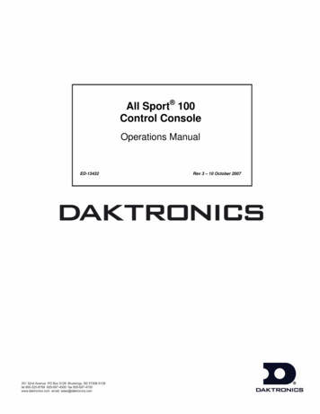
Auto HornDisplayAUTO HORN- ON1-ON, 2-OFFActionPress 1 to select ON (default), or press 2 to select OFF. Theamber LED on the HORN key is on when the Auto Horn featureis enabled. The LED is off when the Auto Horn feature is disabledand the horn is in Manual mode.Manual HornPress HORN to sound the main horn. The horn sounds as long as the key is pressed.Remote Start/Stop ControlsThe All Sport 5500 console lets additional operators control timing functions remotelyusing the Main Clock Start/Stop switch and the Shot Clock Start/Stop switch.Figure 3: Remote Start/Stop SwitchesMain Clock ControlThe Main Clock Start/Stop switch plugs into J4 on the back of the console (Figure 3). Thisunit has a rocker switch for clock start/stop and a button for horn. The horn button soundsthe horn as long as the button is pressed.Shot Clock ControlThe Shot Clock Start/Stop switch plugs into J7 on the back of the console (Figure 3).This unit has a rocker switch for Start/Stop and reset button(s). When a reset buttonis pressed, the shot clock timer is changed to the reset value and stops the timerfrom decrementing. The shot clock timer restarts when the reset button is released. Inindependent mode, the switch starts and stops the shot clock timer when pushed, butdoes not stop when the main clock is stopped. When in synchronized mode, the shotclock timer will stop and start with the main clock switches only if it is running in thebeginning.Refer to Section 4: Basketball Operation (p. 25) for sport-specific information aboutshot clock configurations.Basic Operation9
Setting Radio ChannelsReference Drawings:Channel Selection; Multiple Broadcast Group, Gen IV. DWG-203113Installation Details, Gen VI Channel Selection Guide. DWG-1109870The radio receiver units used in Daktronics scoreboards have a channel (CHAN) switchthat can be set from 1–8. The receivers also have a broadcast group (BCAST) setting. Thebroadcast group defines a group of radio receivers that “listen” to the channel selectedon the channel switch as well as “listen” for data sent out on their broadcast channel.Note: The number of available broadcast groups varies depending on the generationof radio receiver: Gen V receivers have 1–4, while Gen VI receivers have 1–8.Each radio receiver will accept data sent from the broadcast channel of its respectivebroadcast group, as well as data sent from the “Master Broadcast” channel. This isselected when the console is set
201 Daktronics Drive Brookings, SD 57006-5128 www daktronics com/support 800 325 8766 . Figure 1 illustrates a Daktronics drawing label. This manual refers to drawings by listing the last set of digits. In the example, the drawing would be referred to as DWG-1007804. All references to drawing