Transcription
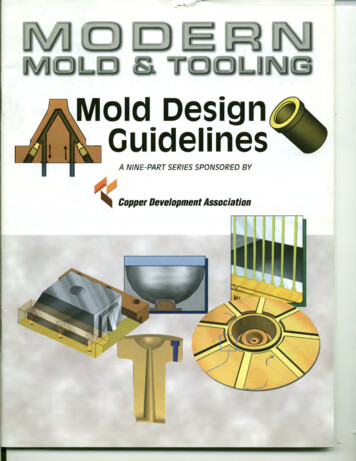
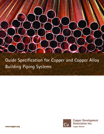
Guide Specification for Copper and Copper AlloyBuilding Piping Systemswww.copper.org
This Guide Specification has been prepared for the use of professionals involved in the design,specification, installation and repair of copper and copper alloy piping systems in buildings. It hasbeen compiled from information sources that the Copper Development Association Inc. (CDA)believes to be competent. However, CDA assumes no responsibility or liability of any kind inconnection with this document or its use by any person or organization and makes norepresentations or warranties of any kind thereby.The requirements contained in this Guide Specification are intended solely as a guide for the designprofessional and represent minimum recommendations and requirements. These should in no waybe substituted for sound engineering practice and judgment. Local codes should be consulted andused to modify this Guide Specification to meet actual project requirements.
Guide Specification for Copper and Copper AlloyBuilding Piping SystemsREVISION 2(02/04/2014)ByCopper Development Association Inc.260 Madison AvenueNew York, NY 10016212/251-7200http://www.copper.org2 Copper Guide Specification
COMMENTARYThis Guide Specification was developed to aid those involved in the writing of specifications and construction documentsinvolving the use of copper and copper alloy piping system products. This Guide Specification contains basic informationon the standards related to the manufacture of copper and copper alloy copper piping system products and materials, thesizes, tempers and configurations available in accordance with these standards, the most common technologies used injoining the tube/pipe and fittings outlined in the standards, system installation requirements, and minimumrecommendations for all of the above in a variety of building piping systems.This Guide Specification contains the following parts:Part 1 – General:Information on the standards referenced throughout the Guide Specification, provisions for qualityassurance for piping system installation and requirements for the delivery, storage and handling ofmaterials referenced in the Guide Specification. The bulk of Part 1 is made up of Section 1.1, which is alist of the most common standards related to the manufacture of copper and copper alloy piping systemproducts and materials. The standards included were written or published by the following: AmericanSociety for Testing and Materials (ASTM), American National Standards Institute (ANSI), AmericanWelding Society (AWS), American Society of Mechanical Engineers (ASME), National Fire ProtectionAssociation (NFPA), Manufacturers’ Standardization Society (MSS), Compressed Gas Association (CGA),and American Society of Sanitary Engineering (ASSE International). The contents of this section areuseful in determining whether the materials/products proposed for use in the piping system aremanufactured in accordance with a nationally recognized standard, or if a component with a nationallyrecognized standard can be generically specified in its place.Part 2 – Products:Specific information on the pipes/tubes, fittings, and joining materials allowed under this GuideSpecification. The majority of this section is comprised of information regarding the composition andusage of the different joining materials allowed for joining copper and copper alloys under this GuideSpecification.Part 3 – Execution:Installation methods and procedures allowed under this Guide Specification for the installation ofcopper and copper alloy piping systems. This includes information on alternate field-fabricatedfittings/connections, requirements for piping joint construction, piping protection, and hanger andsupport spacing. This part also contains Section 3.3 – Pipe and Fitting Applications, which matches thecommon pipe/tube standards with the compatible fittings standards and options available for joiningthe two. The options outlined in this section are based on commercially available pipe/tube and fittingssizes and also consider the availability of components based on variables such as temper and scheduleor type.Part 4 – Piping Systems Applications:Minimum recommendations on pipe/tube, fittings and joints allowed for specific piping systemapplications. This Part also includes specific installation requirements as necessary for each pipingsystem application. Recommendations are included for the following piping system applications: waterdistribution piping systems (above and below ground), soil, waste and vent piping systems (above andbelow ground), storm drainage piping systems (above and below ground), hydronic heating pipingsystems (above and below ground), air conditioning and refrigeration piping systems, fuel gasdistribution piping systems (natural and LP gas), fire sprinkler piping systems, non-flammable medicalgas piping systems and medical vacuum piping systems.3 Copper Guide Specification
PART 1 - GENERAL1.1 - REFERENCED STANDARDSA.B.ASTM International: Standard Specification for 1.2.3.4.5.6.7.ASTM B 32ASTM B 75ASTM B 88ASTM B 280ASTM B 306ASTM B 584ASTM B 8138.9.ASTM B 819ASTM B 82810.ASTM B 83711.12.ASTM A 47ASTM A 536American National Standards Institute/American Welding Society:1.2.3.4.C.D.Solder Metal.Seamless Copper Tube.Seamless Copper Water Tube.Seamless Copper Tube for Air Conditioning and Refrigeration Field Service.Copper Drainage Tube (DWV).Copper Alloy Sand Castings for General Applications.Liquid and Paste Fluxes for Soldering Applications of Copper andCopper Alloy Tube.Seamless Copper Tube for Medical Gas Systems.Standard Practice for Making Capillary Joints by Soldering of Copperand Copper Alloy Tube and Fittings.Seamless Copper Tube for Natural Gas and Liquefied Petroleum (LP)Gas Fuel Distribution Systems.Ferritic Malleable Iron Castings.Ductile Iron Castings.ANSI/AWS A5.8ANSI/AWS A5.31ANSI/AWS B2.2ANSI/AWS C3.4Specification for Filler Metals for Brazing.Specification for Fluxes for Brazing and Braze Welding.Standard for Brazing Procedure and Performance Qualification.Specification for Torch Brazing.ASME International:1.2.3.4.5.6.ASME B1.20.1ASME B16.18ASME B16.21ASME B16.22ASME B16.23ASME B16.247.8.ASME B16.26ASME B16.299.10.11.12.13.14.ASME B16.50ASME B16.51ASME B31.1ASME B31.5ASME B31.9ASME Section IXPipe Threads, General Purpose (Inch).Cast Copper Alloy Solder Joint Pressure Fittings.Nonmetallic Flat Gaskets for Pipe Flanges.Wrought Copper and Copper Alloy Solder-Joint Pressure Fittings.Cast Copper Alloy Solder-Joint Drainage Fittings - DWV.Cast Copper Alloy Pipe Flanges and Flanged Fittings, Class 150, 300,400, 600, 900, 1500, and 2500.Cast Copper Alloy fittings for Flared Copper Tubes.Wrought Copper and Wrought Copper Alloy Solder-JointDrainage Fittings - DWV.Wrought Copper and Copper Alloy Braze-Joint Pressure FittingsCast and Wrought Copper and Copper Alloy Press-Connect Pressure FittingsPower Piping.Refrigeration Piping.Building Services Piping.Boiler and Pressure Vessel Code, Section IX, Welding and BrazingQualification.National Fire Protection Association:1.2.NFPA 13 Standard for the Installation of Sprinkler Systems.NFPA 13DStandard for the Installation of Sprinkler Systems in One- and Two-FamilyDwellings and Mobile Homes.4 Copper Guide Specification
E.3.NFPA 13R4.5.NFPA 14NFPA 14A6.NFPA 257.8.NFPA 54NFPA 99Manufacturers’ Standardization P-89Pipe Hangers and Supports - Materials, Design and Manufacture.Pipe Hangers and Supports - Selection and Application.Silver Brazing Joints for Wrought and Cast Solder-Joint Fittings.Pipe Hangers and Supports - Fabrication and Installation Practices.Compressed Gas Association:1.G.Standard for the Installation of Sprinkler Systems for Residential Occupanciesup to and Including Four Stories in Height.Standard for the Installation of Standpipe and Hose Systems.Recommended Practice for the Inspection, Testing, and Maintenance ofStandpipe and Hose Systems.Standard for Inspection, Testing, and Maintenance of Water Based FireProtection Systems.National Fuel Gas Code.Standard for Health Care Facilities.Pamphlet G - 4.1Cleaning Equipment for Oxygen Service.ASSE International1.ANSI/ASSE 1061Push-fit Fittings1.2 - QUALITY ASSURANCEA.Qualify soldering processes, procedures, and solderers for copper and copper alloy pipe and tube inaccordance with ASTM B 828.B.Qualify brazing processes for copper and copper alloy pipe and tube according to ANSI/AWS C3.4.1.Qualify brazing procedures and brazer performance in accordance with either Section IXof the ASME Boiler and Pressure Vessel Code, or AWS B2.2.1.3 - DELIVERY, STORAGE, AND HANDLINGA.Pipe and tube required by the applicable standard to be cleaned and capped shall be delivered to the jobsite with factory-applied end-caps. Maintain end-caps through shipping, storage, and handling to prevent pipeend damage and prevent entrance of dirt, debris, and moisture.B.Protect stored pipe and tube from moisture and dirt. Elevate above grade. When stored inside, do notexceed the structural capacity of the floor.C.Protect fittings, flanges, and piping specialties from moisture and dirt.5 Copper Guide Specification
PART 2 - PRODUCTS2.1 - PIPE AND PIPE FITTINGSA.Pipe and pipe fittings as used in this specification also refer to tube and tube fittings.B.Pipe Threads: ASME B1.20.1 American Standard Tapered Pipe Threads for factory-threaded pipe andpipe fittings.2.2 - PIPES AND TUBESA.General: The application of the following pipe, tube, and fitting materials and joining methods requiredfor specific piping systems applications are indicated in Part 4 “Piping Systems Applications.”B.Hard Copper Tube: (Drawn Temper)1.ASTM B 75, UNS Number C12200, drawn temper, seamless copper tube, wall thickness asspecified.2.ASTM B 88, Types K, L, and M, drawn temper, seamless copper tube.3.ASTM B 280, Type ACR, drawn temper, seamless copper tube.4.ASTM B 306, Type DWV, drawn temper, seamless copper tube.5.ASTM B 819, Type K and L, drawn temper, seamless copper tube.6.ASTM B 837, Type GAS, drawn temper, seamless copper tube.C.Soft Copper Tube: (Annealed Temper)1.ASTM B 75, UNS Number C12200, annealed temper, seamless copper tube, wall thickness asspecified.2.ASTM B 88, Types K and L, annealed temper, seamless copper tube.3.ASTM B 280, Type ACR, annealed temper, seamless copper tube.4.ASTM B 837, Type GAS, annealed temper, seamless copper tube.2.3 - PIPE AND TUBE FITTINGSA.Wrought Copper, Solder-Joint Pressure Fittings:ASME B16.22B.Cast Copper Alloy, Solder-Joint Pressure Fittings:ASME B16.18C.Wrought Copper, Grooved-End Fittings:Fabricated from ASTM B 75 Seamless Copper Tube.D.Cast Copper Alloy, Grooved-End Fittings:ASTM B 584 Bronze Castings.E.Mechanical Couplings:F.Wrought Copper, Solder-Joint, DWV Drainage Fittings: ASME B16.29G.Cast Copper Alloy, Solder-Joint, DWV Drainage Fittings:H.Cast Copper Alloy Flanges: ASME B16.24, Class 150 and 300, flat-face type.I.Wrought Copper Alloy Unions:1.Threaded Ends:ASTM A 536, ductile iron, or ASTM A 47, malleable iron coupling housingfabricated to manufacturer’s specifications.ASME B16.23ASME B16.22, wrought copper alloy body, hexagonal stock, metal-tometal seating surfaces, and solder-joint, threaded, or solder-joint andthreaded ends.Threads conforming to ASME B1.20.1.6 Copper Guide Specification
J.Cast Copper Alloy Unions:1.Threaded Ends:ASME B16.18, cast copper alloy body, hexagonal stock, with ball-andsocket joint, metal-to-metal seating surfaces, and solder-joint, threaded, orsolder-joint and threaded ends.Threads conforming to ASME B1.20.1.K.Cast Copper Alloy Flare Fittings:ASME B16.26L.Wrought Copper and Copper Alloy Braze-Joint Pressure Fittings:M.Cast and Wrought Copper and Copper Alloy Press-Connect Pressure Fittings:N.Push Fit Fittings: ANSI/ASSE 1061ASME B16.50ASME B16.51THE PROCEDURES BELOW MAY BE USED TO MECHANICALLY FORM BRANCH CONNECTIONS AND COUPLINGS WITHOUT THEUSE OF FITTINGS. DELETE IF THESE PROCESSES ARE NOT ALLOWABLE FOR THE SCOPE OF THIS WORK.O.Mechanically Formed Outlets:Manufacturer’s standard written procedure for forming tee/branch outletfrom pipe and tube shall be followed. Mechanically formed outlets shall have a collar with a height not less thanthree times the thickness of the branch tube wall. The branch shall be notched to conform to the inner curve ofthe run and shall be dimpled or otherwise impeded from penetrating the run pipe/tube. The branch tube shallalso be dimpled or otherwise marked to indicate the location of the notches with respect to the run. Suchmarking shall be at a sufficient distance from the face of the joint to allow for a visual point of inspection afterthe joint is brazed. All joints constructed using this method shall be brazed. Brazing filler metals shall conformto the requirements of Article 2.4 “Joining Materials.”P.Mechanically Formed Couplings:Couplings formed by the expansion of one tube end to form a solder-jointfitting cup may be used. Couplings formed in this manner shall be fabricated using a tool made specifically forthis purpose in accordance with the tool manufacturer’s standard written procedure. The formed fitting cup shallmeet or exceed the dimensional requirements of ASME B16.22 for use with solder-joint connections. Solder fillermetals shall conform to the requirements of Article 2.4 “Joining Materials.” Fitting cup depths that are less thanthose required in ASME B16.22 for soldered joints may be used provided that the cup has a minimum depth equalto three times the wall thickness of the tube and the joint is brazed. Brazing filler metals shall conform to therequirements of Article 2.4 “Joining Materials.”2.4 - JOINING MATERIALSA.Pipe Flange Gasket Materials: Suitable for the chemical and thermal conditions of the piping systemcontents and exterior environment.1.ASME B16.21, nonmetallic, flat, asbestos-free, full-face type for Class 150 and 300 cast copperalloy flanges. 1/8-inch maximum thickness, except whe
3. ANSI/AWS B2.2 Standard for Brazing Procedure and Performance Qualification. 4. ANSI/AWS C3.4 Specification for Torch Brazing. C. ASME International: 1. ASME B1.20.1 Pipe Threads, General Purpose (Inch). 2. ASME B16.18 Cast Copper Alloy Solder Joint Pressure Fittings. 3. ASME B16.21 Nonmetallic Flat Gaskets for Pipe Flanges. 4. ASME B16.22 Wrought Copper and Copper Alloy Solder-Joint
