Transcription
Copper for BusbarsGuidance for Design and Installation
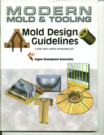
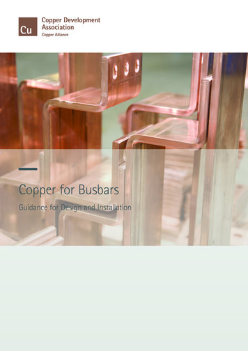
Copper for BusbarsDavid Chapman & Professor Toby NorrisCopper Development Association Publication No 22European Copper Institute Publication No Cu0201Revised May 2014First issued2nd-3rd revisions4th revision5th revision6th-10th revisions11th revision12th revisionReprintedReprinted13th revision14th 196519841996In this new edition the calculation of current-carrying capacity has beengreatly simplified by the provision of exact formulae for some common busbarconfigurations and graphical methods for others. Other sections have beenupdated and modified to reflect current practice.Copper Development Association is a non-trading organisation that promotesand supports the use of copper based on its superior technical performanceand its contribution to a higher quality of life. Its services, which include theprovision of technical advice and information, are available to those interestedin the utilisation of copper and copper alloys in all their aspects. The Associationalso provides a link between research and the user industries and is part of aninternational network of trade associations, the Copper Alliance .Founded in 1996, ECI is a joint venture between the International CopperAssociation, Ltd (ICA), headquartered in New York, representing the majority ofthe world’s leading mining companies, custom smelters and semi-fabricators,and the European copper industry. ECI is also part of the Copper Alliance, aninternational network of industry associations. Its shared mission is to work,with its members, to defend and grow markets for copper based on its superiortechnical performance and contributions to a higher quality of life.David ChapmanDavid Chapman was the Electrical Programme Manager for Copper Development Association in the UK, where his main interests included powerquality and energy efficiency. He was an author and Chief Editor of the LPQI Power Quality Application Guide.Professor Toby NorrisToby Norris is an electrical engineer who has worked in industry and at university. A central interest has been electromagnetic theory, especially inelectric power plant and including superconductors.Cover page picture acknowledgment:High precision copper busbars(Courtesy of H V Wooding Ltd)2 COPPER FOR BUSBARS
Contents1.0 Introduction.61.1 About this Guide . 61.2 Materials for Busbars. 61.2.1Material Requirements.61.2.2Material Choice.71.2.2.1 High Conductivity.71.2.2.1.1 Effect of Temperature on Conductivity.91.2.2.1.2 Effect of Cold Work on Conductivity.91.2.2.2 Mechanical Strength.91.2.2.2.1 Tensile Strength.101.2.2.2.2 Proof Strength.101.2.2.2.3 Hardness.111.2.2.2.4 Resistance to Softening.111.2.2.2.5 Creep Resistance.111.2.2.2.6 Fatigue Resistance.121.2.2.2.7 Bending and Forming.131.2.2.3 Connectivity.131.2.2.4 Maintenance.131.2.3Types of High Conductivity Copper Available.141.2.3.1 Tough Pitch Copper, CW004A and CW005A(C101 and C102).141.2.3.2 Oxygen-free High Conductivity Copper,CW008A (C103) .141.2.4Available Forms.142.0 Current-Carrying Capacity of Busbars.152.1 Design Philosophy.152.2 Calculation of Maximum Current-Carrying Capacity.152.2.1Methods of Heat Loss.152.2.1.1 Convection – Natural Air Cooling.162.2.1.2 Convection Heat Loss - Forced Air Cooling.172.2.1.3 Radiation.182.2.2Heat Generated by a Conductor.212.2.2.1 Alternating Current Effects – the Factor S.222.2.2.1.1 Skin Effect and Skin Depth.242.2.2.1.2 Proximity Factor, Sp.272.3 Conclusion.272A Shape and Proximity Factors for Typical Configurations.282A.1Skin and Proximity Factors for CommonBusbar Shapes.282A.1.1 Single Solid Rods.282A.1.1.1 Shape Factor for Single Solid Rods.282A.1.1.2 Proximity Factor for Single Solid Rods.292A.1.2 Single Tubes.342A.1.2.1 Shape Factors for Single Tubes.342A.1.2.2 Proximity Factors for Tubes.372A.1.3 Single Rectangular Sections.422A.1.3.1 Shape Factor for Rectangular Bars .422A.1.3.2 Approximate Portmanteau Formula forSingle Bars .452A.1.4 Parallel Bars.452A.1.4.1 Proximity Factor - Anti-parallel Currents.452A.1.4.2 Proximity Factor - Parallel Currents.472A.1.5 Three-phase Configurations.492A.1.5.1 Linear Plots.492A.1.5.2 Logarithmic Plots.533.0 Life Cycle Costing. 563.1 Introduction.563.1.1The Future Value of Money –Net Present Value.563.1.1.1 Monthly sitivity Analysis.603.2 Application to an Electrical Installation.603.2.1Installation Design.613.2.2Installation Costs.613.2.3Recurring Costs.613.2.3.1 Maintenance Costs.613.2.3.2 Energy.613.2.4End of Life Costs.683.3 Conclusion.684.0 Short-Circuit Effects. 694.1 Introduction.694.2 Short-Circuit Heating of Bars.694.3 Electromagnetic Stresses.704.3.1Estimating the Forces Between ParallelSets of Bars.724.3.1.1 Round Bars.724.3.1.1.1 Triangular Array.734.3.1.1.2 In-Line Array.744.3.1.2 Bars of Rectangular Section.744.4 Mounting Arrangements.764.4.1Maximum Permissible Stress.764.4.1.1 Moment of Inertia.774.4.2Deflection.784.4.3Natural Frequency.785.0 Busbar Profiles. 795.1 Introduction.795.2 Reasons for Using Profiles.795.2.1Skin Effect Reduction.795.2.2Weight and Cost Saving.795.2.3Integrated Fixings and Mountings.805.2.4Retention of Intellectual Integrity.805.3 Economics of Profiles.805.4 Practical Profiles.805.4.1Manufacturing Process.805.4.1.1 EN 13605.805.4.1.1.1 Straightness, Flatness and Twist.825.4.2Design for Manufacturing.845.4.2.1 Wall Thickness.845.4.2.2 Avoid Sharp Corners.845.4.2.3 Symmetry.845.4.2.4 Be Compact.855.4.2.5 Avoid Deep Narrow Channels.855.4.2.6 Avoid Hollow Chambers.855.4.3Functional Design.85COPPER FOR BUSBARS 3
Contents5.5 Electrical Design Considerations.855.5.1Skin Effect.855.5.2Thermal Dissipation.865.5.3Jointing and Mounting.875.5.4Short Circuit Performance Moment of Inertia.885.6 Calculation of Moment of Inertia of Complex Sections.886.0 Jointing of Copper Busbars. 906.1 Introduction.906.2 Busbar Jointing Methods.906.3 Joint Resistance.916.3.1Streamline Effect.926.3.2Contact Resistance.946.3.2.1 Condition of Contact Surfaces.946.3.2.2 Effect of Pressure on Contact Resistance.946.4 Bolting Arrangements.986.4.1Joint Efficiency.996.5 Clamped Joints.1016.6 Degradation 6.6.3Fretting.1026.6.4Creep and Stress Relaxation.1026.6.5Thermal Expansion.1026.7 Conclusion.102Annex: Coatings. 103A1.0 Introduction. 103A2.0 Reasons for Coating. 103A2.1Coating to Provide Electrical Insulation. 103A2.2Coating to Inhibit Corrosion. 103A2.2.1 Metal Coatings. 103A2.2.2 Non-Metallic Coatings. 103A2.3Coating to Increase Current Rating. 103A2.4Coating for Cosmetic Purposes. 104A2.5Coating to Improve Joint Performance. 104A3.0 Methods of Coating. 104A3.1Factory Application Methods. 104A3.1.1 Extrusion.
greatly simplified by the provision of exact formulae for some common busbar configurations and graphical methods for others. Other sections have been updated and
