Transcription
THE ELECTRICAL CONDUCTIVITY OF COMMERCIALCOPPERByF.A. Wolff andJ.H. DellingerCONTENTSPageI.Introduction[04*.Notes on table of standard values2. Table I.Standard valuesofthis investigation3. ScopeThe experimental worki.II.12.III.0405060808The Thomson bridge methodThe apparatusIIResults obtained1Resistivity of commercial copper2.Copper of especially high conductivityData on hard-drawn aluminum3.331415IV. Discussion of resultsl7J7!73.Annealed copper wires(a) Summary of above data(6) Summary of data from American Brass CompanyHard -drawn copper wiresThe highest conductivity found4.Aluminum195.Temperature12.coefficient of171818copper19V. Conclusions12.3.4.5.6.7.VI.JJ21Best value for the resistivity of annealed copperDensity of copperTemperature coefficient of annealed and of hard -drawn copper.Percent conductivityData for use in wire tablesThe expression of resistivity in ohms per meter-gramDesirability of an international standard of copper conductivity.Summary2122222223232425103
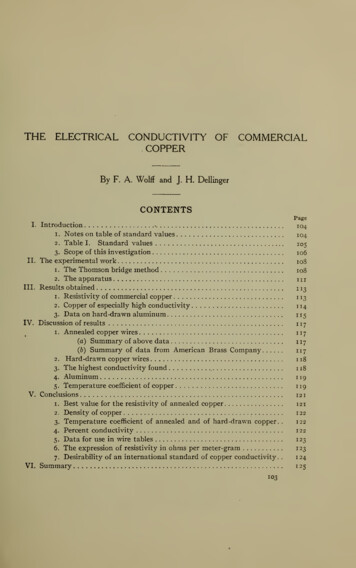
Bulletin of the104I.The valuesBureauofStandards[Vol. 7,INTRODUCTIONin use for the conductivity, resistivity,ture coefficient of copper vary considerably.and tempera-The standardues for annealed copper as usedby variouscountries are given in Tableon the adjoining page:1.No. iI,val-institutions in differentNOTES ON TABLE OF STANDARD VALUESThe values given in the table for the various temperatures arecomputed from the values at the particular standard temperaIn each columnture, which are indicated by heavy-faced type.the temperature coefficient of that columnused in computingthe resistivity in ohms per meter-gram at the various temperatures.The data for the English values (col. 1) were obtained from thereport of the Engineering Standards Committee, August, 1904.The values for " Normal Kupfer" (col. 2) were computed fromthe data given in E. T. Z. 17, 402; 1896, and "Normalien, etc.,d. Verbandes Deutscher Elektrotechniker, " 1907, page 68.Thevalue for conductivity given was reduced to meter-gram resistivity by the use of the density given as standard, 8.91.Thevalues in column 3 are calculated on the assumption of a densityof 8.89.The German " Normal Kupfer" is in use also in Austria.The Matthiessen value as computed by Lindeck (col. 4) isbased on the data given in C. Hering's " Conversion Tables"(John Wiley and Sons, N. Y., 1904), page 104, and was reducedto the meter-gram basis on the assumption of the density, 8.89,and Matthiessen's temperature formula.The values which were adopted by the American Institute ofElectrical Engineers in 1893 are given in col. 5.They werederived from the results Matthiessen published in 1862.(Theo and 20 meter-gram values are equivalent to 1.59425 andIn 1908 Mat1. 72 1 28 micro-ohms per cm cube, respectively).thiessen's temperature formula was dropped by the A. I. E. E.and the linear temperature coefficient of 0.0042 at o C wasadopted (col. 6) this vitiated the old wire table of the Instituteand, as the o value of the resistivity was retained, the resistivityat all other temperatures was altered.The 20 value of theresistivity was retained by the Bureau of Standards (since themeasurements of Matthiessen at 20 C were probably at least as;is
1WolffDellingerJCopperElectrical Conductivity of MCOc CN3* "3 .g - *31-4voO03 0)OOOt- CMOOO** IOvO1-1raw "3 vOOOOOOs s CNMPuao 105CO .U« -CO "0 si 1—3 -HG u2JVVO«»IH3cbrawc1—OIOOOm*Cvj0?in* inOVCOC 00co2au 7Oescdcd -HOAo w 00OVWMM CB00CO voOcstNt u- —VO* OOesCOV CO*- m —»»- M10COIO10 IN«* vOVOOOOv 1— VOOVCO00CO DQ T3CMOov« C u HatCNr .Oi-HwHw*rHCOo*«omi-Hi-Hw1-u DI-H«—«-MMH" Uup,flt-HGID1 w U JPQImW 25HO 15 & %-M1—o10l"1rt a00 as « 3 ."310c-S *"irCO COcb CO H3a(82" t- n3s DPntow"* S.352*flg L wt OvOvQoo UIO00CMOVOt »Irt1010 H1-4SHming8.89ny»M "2 3-810 4 V-c[0 ,J?ea23.Eht y—lCMOVCO00HOCOCOOVT-l *t-Hf-HOm m"*rPhwuH -;*7;I—BCO v%wQH wt Kup-uouwD4t omCM«*OO !fCMOVCO && OCOua oovmovCOHObo »:o-2oO 05 3 luU 2« -g% »0. 00.2200COW§ 5(0Tl-00»-J --&M03—,*jt H0012—.10c Tf00Tf«n*— «-Tfv T-«mCMT»-OOO )TfOOCMovCO « o00CO«i 'd Sbo g*91f sD Sh"3. 84)CO"J3M« -(toua L rWS—'O- h'OOSov a "a w 52.1VOCO* HOCO« 100010T—VO0000CMTl"Tj- COVOT—vr »-iv gaiOOO CMT»" ** OVCOOOOVO00CO a tO 3V*jJSCOO J5 - Om1-1CMmCM CJ3H
106Bulletin of theBureauofStandardsreliable as those at lower temperatures;andivoi. 7,since the 20No. 1valueeven on the old basis) and the temperature coefficient of 0.0042 at o C was adopted (col. 7)Since a more accurate value for the temperature coefficient hasbeen obtained at the Bureau of Standards, it has been applied togive the values in col. 8, which represent the present practice ofthe Bureau.was the onein practical use3.The foregoing;SCOPE OF THIS INVESTIGATIONtablemakes evident the needmorereliablefor data tobe usedThe matter ofstandard values.obtaining such data having been submitted to the Bureau ofStandards by the American Institute of Electrical Engineers, aninvestigation has been made of the copper furnished for electricalThe cooperation of a number of the important refinersuses.and manufacturers of copper wire was secured. These companiesfurnished samples for measurement and information regardingIncidental to the investigatheir material and their practices.tion of copper it was thought desirable to secure some data onaluminum, and accordingly the cooperation of the chief producer of aluminum was also secured. The companies whose material was represented in the investigation were the following:inestablishing{Calumet and Hecla Smelting Works, Hubbell, Mich.Quincy Mining Co., Hancock, Mich.Buffalo Smelting Works, Buffalo, N. Y.American Smelting and Refining Co., Maurer, N. J.The Baltimore Copper Smelting and Rolling Co., Baltimore, Md.Electrolytic The U. S. Metals Refining Co., Chrome, N. J.Refiners.JRaritan Copper Works, Perth Amboy, N. J.Nichols Copper Co., Laurel Hill, N. J.A.Grammont, Pont-de-Cheruy, France.American Brass Co., Waterbury, Conn.John A. Roebling's Sons Co., Trenton, N. J.Wire Manu- Standard Underground Cable Co., Perth Amboy, N. J.facturers.Heddernheimer Kupferwerk und Siiddeutsche Kabelwerke, Frankfurtam Main, Germany.1Kabelfabrik-und Drahtindustrie-Actien-Gesellschaft, Vienna, Austria.Aluminum]Wire Manu- Aluminum Company of America, Pittsburg, Pa.facturer.JEleven of these companies kindly furnished samples and information at the request of the Bureau of Standards, and the Bureaudesires hereby to express its thanks and appreciation for their
Electrical Conductivity ofDelimiter]Copper107Samples of the products of the other four companiesobtainedin other ways.wereParticular thanks is due Mr. W. H.Bassett, of the American Brass Company, who has taken greatinterest in the work, and who has contributed a valuable set ofassistance.data on conductivity; and to Mr. Wm. Hoopes, of the AluminumCompany of America, who furnished valuable data on aluminumand to Mr. E. A. C. Smith, of the Baltimore Copper Smeltingand Rolling Company, who supplied valuable information and aquantity of specially refined cathode copper. The authors desirealso to express their appreciation of the assistance of Mr. E. E.Weibel, who made some of the measurements.A considerable number of the most important refiners and manufacturers of copper wire in this country are included in the abovelist; Germany, France, and Austria are each represented by onecompany. Since most of the world's copper is refined in thiscountry, and the results of the measurements on the foreignsamples showed no particular difference from the American samples, all the results will be given without distinguishing the foreign from the American product. The various companies wereasked to furnish representative samples of their regular commercialproduct, both hard-drawn and annealed, and from two to twentysamples were received from each. It is not believed that themeasurements made upon the few samples from each companyindicate accurately the average of the product of that companybut it is considered that the mean of all the measurements indicatesvery well the average of the present copper of commerce. TheResults are also given for measurementsresults are given below.on a few aluminum wires, together with the data on aluminumfurnished by the Aluminum Company of America.An effort was also made to determine what was the highest conductivity obtainable without extraordinary experimental precautions and expense, and the measurements made upon a fewysamples of copper of especially high conductivityare, therefore,was considered desirable also to make a completeinvestigation of the effect upon the conductivity of drawing toprogressively smaller sizes, and to study the question of annealing,but these two matters have had to be dropped because of thepressure of other work it is hoped that they can be taken up at aalso given.It;later time.
108Bulletin of theII.BureauofStandards[Vol. 7. x . 1THE EXPERIMENTAL WORKThe samples upon which measurements were made were wiresNos. 6 to 18, B. and S. gage, about 120 cm in length. Most of thesamples were No. 12. The resistivity in ohms per meter-gramand percent conductivity were computed from measurements ofthe length, mass, and resistance. The resistivity in ohms permeter-gram is the product of the resistance per meter and themass per meter. The percent conductivity is computed by dividing 0.153022 by the resistance per meter-gram at 20 C.(Thisfigure is the value assumed by the Bureau of Standards as representing the "Matthiessen Standard" at 20 C.It corresponds toC, on an assumed1. 72 1 28 micro-ohms per centimeter cube at 20density of 8.89.)The Thomson bridge method was used formeasuring the resistances, and an accuracy of 0.0 1 percent waseasily attained.The resistance of the copper sample was compared with the resistance of a copper standard in the same bathas the test sample, thus eliminating the necessity of very accu-rate temperature measurement.Theresistances of the copperstandards were carefully checked from time to time against man-ganin standards; in these measurements, of course, temperatureas well as resistance had to be measured accurately.The accuracy of the resistivity and conductivity values obtained is believedto be within 0.03 percent, a limit determined chiefly by theuncertainty of the total length measurement (many of the wireswere not entirely free from small bends) and the lack of uniformity of cross-section of the wires.1.THE THOMSON BRIDGE METHODThe Thomson bridge method was first described by Sir Wm.Thomson, 4 in 1862. Hence it is called the "Thomson bridge" or"KelvinAdiagram of the connections isgiven in Fig. 1. A and B are the low resistances to be compared.5 and 7, 10 and 1, are the "branch points" or "potential points"between which are the resistances considered, a, na, a' and n'a'The theory of theare ratio arms of relatively high resistance.method may be understood from Fig. 2. This figure representsdoublebridge.",4Phil.Mag. 24,149; 1862.
Wolff"IElectrical Conductivity ofDellinger\Copper109a simple Wheatstone bridge. The simple bridge can not be usedfor low resistances, because the connecting resistance between AandBintroduces an errorifthe galvanometerFig.isconnected to any1(The resistances 7 8 and 9 10 are theof the points 7, 8, 9, or 10.resistances of the adjacent "current terminals" of A and B.Theresistancebetween8and 9isthe " link " connectingJAand B.)2Fig. 2However,atif itsome point12were possible to bring the galvanometer lead insuch that10 1212 7since, for zero deflection of the58397—B 10A 12118*BA(I)galvanometer,127naa(2)
noweBureauBulletin of theofStandardsivoi. 7,n.ihave, for a bridge balance, n(3)The equivalent of this is accomplished in the Thomson bridgeby shunting 10 7 with a relatively high resistance, connecting thegalvanometer to a point,12, Fig. 1,and adjustingn'a' or a' sothatn'a'Ba'ThebestbymethodAof accomplishing this5adjustment(firstpub-remove the link, 8 9, thus reducingthe bridge to a simple Wheatstone bridge, and vary a' or n'a' fora galvanometer balance. Then n n'. The link is then replaced,and the main ratio, na a, adjusted until a galvanometer balanceThe "link-out" balance is, of course, disturbed byis attained.lishedJ.H. Reeves)isto:this adjustment, unless{n'a':a')isvaried simultaneously withhave the "auxiliary ratio," n'a': a',similar to the main ratio, and to vary them simultaneously forthe "link-in" balance; thus the "link-out" adjustment is not(na:a).It is preferable toAdouble set of ratio coils frequently used is theIf,O. Wolff type, and it was used in the work of this paper.however, the main and auxiliary ratios can not be varied simultaneously, the "link-in" balance may be made by varying thedisturbed.main ratio, then the link is taken out and the balance restoredby varying the auxiliary ratio, and then the link is replaced andthe main ratio again varied, and so on by successive approximations until both balances areThemade.variation of a' or n'a' for the "link-out" balancemay beaccomplished by means of a variable resistance in series with a' orn'a' at 7 or 10. A very satisfactory form for this variable resistance is a small glass tube of mercury, the resistance between theends of which can be varied by changing the depth to which anamalgamated copper wire is immersed in it. If the range of themercury resistance is insufficient, a manganin wire, with sliding,clamp contact, may be put in series with it. Another method forobtaining the "link-out" balance is to have a slide-wire betweena' and n'a' along which moves the galvanometer contact.,,6Proc. Phys. Soc, London, 14, p. 166; 1896.
DeiungerlElectrical Conductivity ofThe connectinginCopperbetween the branch-point, i, andthe end of na, 2, and between 5 and 4, are usually not negligible.One method of procedure is to shift the battery leads from theirnormal points of connection, 6 and 11, to 4 and 2, with the linkout, and measure the change of balance of the bridge by varyingone of the
Wolff1 DellingerJ ElectricalConductivityofCopper 105 1-4 v Pua Uo JV c Q D T3 C rt-MC u «— 4 «-M MH" U 1— 1 wU J L PQ3 a H D S H & u o « -(to L cd C IS CO MCO 3*"3 .g - * 303 raw 0) "3. « -CO "0 si3 IHG 1—u2 -H 3cb raw