Transcription
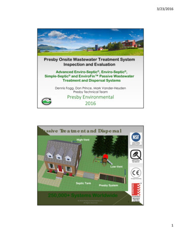
Presby WastewaterTreatment SystemsIndianaDesign and Installation ManualforAdvanced Enviro-Septic Wastewater Treatment System Minimizes the Expense Protects the Environment Preserves the SitePresby Environmental, Inc.An Infiltrator Water Technologies CompanyThe Next Generation of Wastewater Treatment Technology143 Airport Rd., Whitefield, NH 03598Tel: 800-473-5298 Fax: tal.com Copyright August 2019, Presby Environmental, Inc. All Rights Reserved.
The information in this manual is subject to change without notice. We recommend that you check your state’s pageon our website on a regular basis for updated information. Your suggestions and comments are welcome. Pleasecontact us at: 800-473-5298.The Next Generation of Wastewater Treatment TechnologyPresby Environmental, Inc.143 Airport RoadWhitefield, NH 03598Phone: 1-800-473-5298 Fax: (603) 837-9864Website: www.PresbyEnvironmental.comThe products and methods depicted in this manual are protected by one or more patents. For more information:Pat. www.presbyeco.com/patents.Advanced Enviro-Septic is a registered trademark of Presby Environmental Inc.Enviro-Septic is a registered trademark of Presby Environmental, Inc.Simple-Septic is a registered trademark of Presby Environmental Inc.IMPORTANT NOTICE: This Manual is intended ONLY for use in designing and installing PresbyEnvironmenntal’s Advanced Enviro-Septic Wastewater Treatment System. The use of this Manual with anyother product is prohibited. The processes and design criteria contained herein are based solely on ourexperience with and testing of Advanced Enviro-Septic . Substitution of any other large diameter gravellesspipe will result in compromised treatment of wastewater and other adverse effects. Presby Environmental, Inc. August 2019All Rights Reserved Presby Environmental, Inc., Indiana Design & Installation Manual August 2019 Edition-i-
TABLE OF CONTENTSNumberPage Number1.0Background . 12.0Ten Stages of Wastewater Treatment . 23.0AES System Components . 34.0Introduction. 35.0Design Criteria. 46.0Indiana State Specific Information . 57.0Basic Serial Distribution . 88.0Combination Serial Distribution . 99.0Butterfly Configuration . 1010.0Curved Beds. 1111.090 Beds . 1112.0Multiple Bed Distribution . 1113.0Non-Conventional System Configurations . 1214.0Subsurface Drainage, Surface Diversions and Segment Drains . 1215.0Table A – Pipe Required . 1316.0Table B – System Sand Bed Area (SSBA) Required . 1317.0Table C: System Pipe Row Length and Pipe Layout Width (PLW) . 1418.0Design Procedure (Single Bed). 1419.0Pumping & Dosing . 1820.0Venting Requirements . 1921.0Site Selection . 2122.0Installation Requirements, Component Handling and Site Preparation . 2223.0System Bacteria Rejuvenation and Expansion . 2524.0Operation & Maintenance . 2525.0Glossary . 2626.0Indiana System Installation Form . 30 Presby Environmental, Inc., Indiana Design & Installation Manual August 2019 Edition-ii-
1.0BackgroundLiquid that exits from a septic tank (“effluent”) contains suspended solids that can cause traditional systems to failprematurely. Solids can overload bacteria, cut off air required for aerobic bacterial activity, and/or seal the underlyingsoil, interfering with its ability to absorb liquid. By utilizing simple yet effective natural processes, the AdvancedEnviro-Septic Wastewater Treatment System treats septic tank effluent in a manner that prevents suspended solidsfrom sealing the underlying soil, increases system aeration, and provides a greater bacterial treatment area (“biomat”)than traditional systems.1.1Why Our System ExcelsThe Advanced Enviro-Septic Wastewater Treatment System retains solids in its pipe and provides multiple bacterialsurfaces to treat effluent prior to its contact with the soil. The continual cycling of effluent (the rising and falling ofliquid inside the pipe) enhances bacterial growth. This all combines to create a unique eco-system that no otherpassive wastewater treatment system is designed to offer. The result is a system that excels by being more efficient,last longer, and have a minimal environmental impact.1.2System Advantagesa) costs less than traditional systemsb) eliminates the need for washed stonec) often requires a smaller aread) installs more easily and quickly than traditional systemse) adapts easily to residential and commercial sites of virtually any sizef) adapts well to difficult sitesg) develops a protected receiving surface preventing sealing of the underlying soilh) blends system into sloping terraini) increases system performance and longevityj) tests environmentally safer than traditional systemsk) recharges groundwater more safely than traditional systemsl) made from recycled plastic1.3Patented TechnologyAt the heart of Advanced Enviro-Septic (AES) is a patented corrugated, perforated plastic pipe with interior skimmertabs and cooling ridges. AES pipe is surrounded by three filtering, treatment and dispersal layers (see further productdescriptions below). AES pipes are assembled and installed in a bed of specified System Sand (IN DOT 23 sand)which can either be below the ground or above. AES systems are completely passive in their treatment ofwastewater, requiring no electricity, motors, alarms, computers, etc.1.4Advanced Enviro-Septic (AES)The Advanced Enviro-Septic pipe is assembled into an onsite wastewater treatment system that has beensuccessfully tested and certified to NSF 40, Class I (a certification typically given to mechanical aeration devices),BNQ of Quebec, Class I, II, III and Cebedeau, Belgium standards. Advanced Enviro-Septic is comprised ofcorrugated, perforated plastic pipe, Bio-Accelerator fabric along its bottom which is surrounded by a layer ofrandomized plastic fibers and a sewn geo-textile fabric. Advanced Enviro-Septic creates an eco-system designed tosimultaneously purify and disperse effluent after primary treatment by a septic tank. Advanced Enviro-Septic is the“next generation” of our Enviro-Septic technology. The AES product incorporates Bio-Accelerator, a proprietaryenhancement that screens additional solids from effluent, accelerates treatment processes, assures even distributionand provides additional surface area. Each foot of Advanced Enviro-Septic provides over 40 sq. ft. of total surfacearea for bacterial activity. Caution: see para. 6.7, pg. 6 concerning product substitutions. Presby Environmental, Inc., Indiana Design & Installation Manual August 2019 Edition-1-
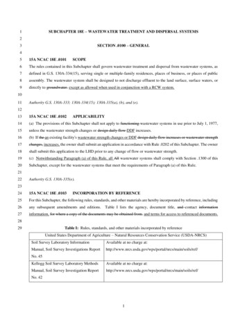
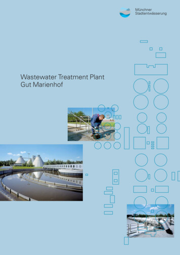
2.0Ten Stages of Wastewater TreatmentThe Advanced Enviro-Septic Wastewater Treatment System's10 STAGES OF TREATMENTAdvance Enviro-Septic (AES)SYSTEM SANDSEWN SEAM(ALWAYS UP)AIR SPACE101SCUM2EFFLUENT2SLUDGE SYSTEM SANDCROSS SECTION8 9734GEO-TEXTILEFABRIC6COARSEFIBERSSKIMMER TABS5RIDGESBIO-ACCELERATOR FABRICStage 1:Warm effluent enters the pipe and is cooled to ground temperature.Stage 2:Suspended solids separate from the cooled liquid effluent.Stage 3:Skimmers further capture grease and suspended solids from the existing effluent.Stage 4:Pipe ridges allow the effluent to flow uninterrupted around the circumference of the pipe and aid incooling.Stage 5:Bio-Accelerator fabric screens additional solids from the effluent, enhances and accelerates treatment,facilitates quick start-up after periods of non-use, provides additional surface area for bacterial growth,promotes even distribution, and further protects outer layers and the receiving surfaces so they remainpermeable.Stage 6:A mat of coarse, randomly-oriented fibers separates more suspended solids from the effluent.Stage 7:Effluent passes into the geo-textile fabrics and grows a protected bacterial surface.Stage 8:Sand wicks liquid from the geo-textile fabrics and enables air to transfer to the bacterial surface.Stage 9:The fabrics and fibers provide a large bacterial surface to break down solids.Stage 10:An ample air supply and fluctuating liquid levels increase bacterial efficiency. Presby Environmental, Inc., Indiana Design & Installation Manual August 2019 Edition-2-
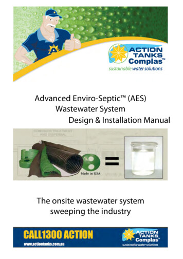
3.0AES System Components3.1Advanced Enviro-Septic Pipea) Plastic pipe made with a significant percentage of recycled materialb) 10 ft. sections (can be cut to any length)c) Ridged and perforated, with skimmer tabs on interiord) Supplied with Bio-Accelerator along bottom of the pipe (the sewn seam indicates“this side up”).e) Surrounded by a mat of randomly oriented plastic fibersf) Wrapped in a non-woven geo-textile fabric stitched in placeg) Exterior diameter of 12 in.h) Each 10 ft. section has a liquid holding capacity of approx. 58 gallonsi) A 10 ft. length of pipe is flexible enough to bend up to 90 3.2Offset AdapterAn offset adapter is a plastic fitting 12 in. in diameter with a 4 in. hole designed to accept a 4 in.inlet pipe, raised connection or vent pipe. The hole is to be in the 12 o’clock position, 7 in. abovebottom of the AES pipe. When assembling pipes into rows, note that the geo-textile fabrics areplaced over the edges of the Offset Adapter and Couplings.3.3CouplingA coupling is a plastic fitting used to create a connection between two pieces of pipe. Note thatthe couplings are wide enough to cover 1 or 2 pipe corrugations on each of the two pipe endsbeing joined. The couplings feature a snap-lock feature that requires no tools. Whenassembling pipes into rows, note that the geo-textile fabric does not go under couplings. Pullfabric back, install coupling, and then pull fabric over coupling. Also note, during installation incold weather, couplings are easier to work with if stored in a heated location before use; such asa truck cab.3.4Raised ConnectionA raised connection is a PVC Sewer & Drain pipe configuration which is used to connect pipe rows. Raisedconnections extend 2 in. to 4 in. into pipe and are installed on an angle (as shown below). All PVC joints should beglued.4.0Introduction4.1Presby Environmental StandardsAll AES systems must be designed and installed in compliance with the procedures and specifications described inthis Manual and in the product’s Indiana approval.4.2Indiana RulesThis manual is to be used in conjunction with Rule 410 IAC 6-8.3 for residential systems effective 5-9-14 and withRule 410 IAC 6-10.1 for commercial systems effective 5-17-14.4.3Conflicts between Indiana Rules & ManualIn the event of contradictions between this Manual and Indiana State Department of Health (ISDH) regulations, theISDH and Presby Environmental, Inc. (800-437-5298) must be contacted for technical assistance.4.4Certification RequirementsAny designers and installers who have not previously attended a Presby Environmental, Inc. “Certification Course”are required to obtain Presby Certification. Certification is obtained by attending a Certification Course presented byPresby Environmental, Inc. or its sanctioned representative. Certification can also be obtained by viewing tutorialvideos on our website (high speed connection required) and then successfully passing a short assessment test, Presby Environmental, Inc., Indiana Design & Installation Manual August 2019 Edition-3-
which is also available over the internet. All professionals involved in the inspection, review or certification of AESSystems must also become Presby Certified.4.5Exceptions to Presby RequirementsTo resolve any conflicts with or exceptions to any requirements in this Manual, the ISDH and Presby Environmental,Inc. must be contacted.4.6Technical SupportPresby Environmental, Inc. provides technical support to all individuals using our products. For questions about ourproducts or the information contained in this Manual, or to register for a Certification Course, please contact us at 1800-473-5298.5.0Design CriteriaThis section presents the various design configurations of the AES system. The system configuration to be used isdetermined by characteristics of the receiving soils, vertical distance to the SHWT or restrictive feature, othercharacteristics specific to the particular site and the design daily flow.5.1Advanced Enviro-Septic SizingAES systems use the bed sizing tables, pipe and installation requirements noted in this manual.5.2Converging Flows RestrictionSystems must not be located where surface or ground waters will converge, causing surface water flow to becomeconcentrated or restricted within the soil absorption field.5.3Distribution Box (D-box)A D-box is used to divide flow to more than one portion of the bed. Distribution boxes are required for all CombinationDistribution and Pump Systems, but NOT for Basic Serial Systems. There is no minimum separation distancerequirement from a D-box to the AES pipe.5.4Distribution Box ManifoldA manifolded distribution box joins several outlets to help divideflow more accurately. Dividing flow to multiple beds is a commonuse of manifolded D-boxes. All outlets delivering effluent to thefield must have a flow equalizer. Do not place an equalizer onvent outlets.5.5Flow Equalizers RequiredAll distribution boxes used to divide effluent flow require flow equalizers in outlets feeding AES pipe. Equalizers aredesigned to help compensate for an out of level distribution box, which is likely to occur over time, and maintain abalanced flow to each distribution box outlet leading to the field. Flow equalizers are limited to a maximum of 15 GPMper equalizer and are never placed on D-box outlets used for venting.5.6End-to-End Preferred Over Side-to-SideIf site conditions permit, end-to-end multiple bed configurations are preferable to side-to-side configurations.5.7Row Elevations for Sloping SitesElevations must be provided on the construction drawing for each AES row in the bed system.5.8Row OrientationRows must be laid level to within /- ½ in. and must be placed along the contour of the site. The minimum center-tocenter spacing is 1.5 ft. The center-to-center spacing may be larger, but not less than the minimum requirement. Thedesigner must clearly state the row elevations on the system’s construction drawing(s).5.9Row RequirementAll beds must have at least 2 rows with a minimum row spacing of 1.5 ft. center-to-center. For level beds the rows arecentered in the middle of the basal area and for sloping beds the rows are grouped at the high side of the basal area.For additional information regarding row placement, see para. 6.2, pg. 5.5.10 Maximum and Minimum Row LengthsTo maintain efficient effluent cycling within the AES pipe, the maximum row length is 100 ft. (not including SystemSand) and the minimum row length is 30 ft. For repair or replacement systems, the "best judgment" clause of 410 IAC6-8.3-53(i) must be followed. Fields are to be constructed as long and narrow as the site permits. Presby Environmental, Inc., Indiana Design & Installation Manual August 2019 Edition-4-
5.11Pump System Requirementsa) The use of pressure distribution within an AES system is not permitted.b) Pump systems to gain elevation are allowed.c) Systems incorporating pumps to gain elevation must use differential venting and velocity reduction tocontrol liquid flow.Reference: See Pump System Requirements, para. 19.0, pg. 18.5.12Septic Tank and Distribution Box Elevationsa) The outlet of a distribution box must be set at least2-in. above the highest inlet of the AES row.b) If a distribution box is not used and the septic tankis connected directly to a Basic Serial system (seepara. 7.0 on pg. 8): the outlet of the septic tankmust be set at least 2-in. above the highest inlet ofthe AES row, but never sloped less than 1% (approximately 1/8 in. per foot.)5.13 System Side Slope TapersIf a bed extends above grade, the IN DOT 23 sand and the cover soils on the system must have side slope tapersuntil it meets the original grade. Side slope tapering is to be no steeper than 3:1; steeper side slopes require ISDHapproval. The side slope taper begins 3 ft. from the AES pipe, measured parallel to the system slope - if any – (seeillustrations in para. 6.12, pg. 7 ).5.14 Ten Foot Increments Work BestIt is easier if row lengths are designed in 10 ft. increments since AES pipe comes in 10 ft. sections. However, ifnecessary, the pipe is easily cut to any length to meet site constraints. Using 5 ft. increments minimizes waste ofpipe material.5.15 Velocity ReductionReduce the velocity of liquid entering AES pipe to eliminate turbulence. Adistribution box which includes a Rule-compliant baffle, 90 bend with weep hole,or inlet tee may be adequate for velocity reduction in most systems. Whenpumping to gain elevation, pump to a large distribution box or equivalent (like asmall septic tank that feeds the D-box) with proper baffles or tee at the end of thedelivery line.5.16 Venting RequirementsVenting is required for all AES Systems. See Venting Requirements, para. 20.0, pg. 19.6.0Indiana State Specific Information6.1Infiltrative Surface (Bed Bottom)The infiltrative surface is defined as the bottom of the System Sand (IN DOT 23 sand) bed. Vertical separationdistances are measured from the infiltrative surface.6.2Sloping Sites and Sloping SystemsBed ElevationSubsurface(Infiltrative Surface 4” Below Original Grade)Elevated(Infiltrative Surface 4” Below Original Grade)Bed ConfigurationLevelSloping ½% Site Slope ½% Site Slope ½% Site Slope ½% Site SlopeMaximum SiteSlope15%6%Notes:1. For sloping systems, the rows are grouped at the high side of the System Sand bed (see illustrations in para. 7.0, pg. 8 andpara. 8.0, pg. 9).2. The percentage of system slope in all drawings (in this manual) refers to the slope of the AES system and not the existingterrain unless otherwise noted. Systems should be constructed to follow the original site grade when possible.3. The slope of the site and/or the system may contain more than one slope provided the maximum allowed slope is notexceeded (see para. 13.1, pg. 12).4. Maximum Site Slope specification is dictated by the Rule. Presby Environmental, Inc., Indiana Design & Installation Manual August 2019 Edition-5-
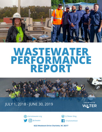
6.3Design Daily FlowDesign daily flow is calculated in accordance with Indiana rules. For daily design flows of less than two bedrooms,contact Presby Environmental for design criteria and written authorization.6.4Subsurface (In-Ground) Systema) The infiltrative surface must be a minimum of 4 in. below the original grade.b) Subsurface systems must have at least 6 in. of System Sand (IN DOT 23 sand) below all AES pipes.c) Subsurface systems are allowed on slopes up to 15%d) Subsurface systems are designed along the contour while adhering to minimum separation distances torestrictive features.e) When the System Sand (IN DOT 23 sand) or the cover material extends above original grade, the IN DOT23 sand and the soil material covering the system must have side slopes tapering at a maximum of 3:1.6.5Elevated Bed Systemsa) To qualify as an elevated bed, the infiltrative surface must be less than 4 in. below the original grade.b) Elevated systems must have at least 12 in. of System Sand (IN DOT 23 sand) below all AES pipes (seepara. 6.6, below)c) Cover material extensions (materials extending beyond the edges of the AES pipe perimeter) are requiredbefore beginning the slope tapers (see para. 6.6 below).d) Elevated systems are allowed on slopes up to 6%.e) While beds elevated above original grade are required to follow the contours of the original grade, thespacing and slope of the pipes shall remain consistent from end to end.6.6Section Views of Subsurface and Elevated Systems6.7AES Pipe SubstitutionsSubstitutions to the AES Pipe shown on the approved septic system design is not allowed without the writtenapproval of the health department that approved the design and the system’s designer. This includes substitutinganother manufacturer’s pipe or even other models of Presby pipe. For example: if AES pipe was specified by theapproved plan, no other competing product can be substituted without written approval and an amended design planshowing the substitution. AES may be used as a substitute for Enviro-Septic (ES) or Simple-Septic (SS) products thathave been specified by the approved plan with an amendment.6.8System Sand Requirements for All BedsIt is critical to the proper functioning of the system that the proper amount and type of System Sand be installed.System Sand must be clean, granular sand, free of organic matter and must adhere to Indiana DOT 23 sandrequirements. Material passing the #200 sieve must be verified by washing the sample. In this manual, the termsSystem Sand and Indiana DOT 23 sand are used interchangeably. The Presby Spec-Check is a device created tohelp determine the suitability of material for use as System Sand without the need for an expensive lab test. Go towww.PresbyEnvironmental.com for more details.6.9System Sand Bed Height DimensionsThe height of an AES system measures 21-inches minimum for In-Ground Systems and 27-inches minimum forElevated Systems (not including cover material – see illustrations in para. 6.6 above):a) 6-inches minimum of System Sand below the AES pipe for In-Ground Systems;b) 12-inches minimum of System Sand below the AES pipe for Elevated Systems;c) 12-inches diameter of the AES pipe; andd) 3-inches minimum of System Sand above the AES pipe. Presby Environmental, Inc., Indiana Design & Installation Manual August 2019 Edition-6-
6.10 System Sand ExtensionSystems that slope more than 10% require a 3 ft. System Sand extension on the down slope side of the System Sandbed (see illustration in para. 6.12 below). The System Sand Extension area (any part of the System Sand bed that ismore than 1 ft. away from the AES pipes) is required to be a minimum of 6 in. deep. The System Sand extensionshould not be confused with the “cover material extension,” which refers to the material used to cover the field.6.11 Sand FillIndiana DOT 23 sand is to be used as “sand fill” whenever sand fill is required.6.12Cover Material Extensions and Side Slope Tapersa) A 3 ft. cover material extension (measured from the AES pipe) is required on each side of any bed thatextends above the original grade, which has a system slope of 10% or less, before the side slope taperingcan begin.b) If the system slope is greater than 10%, the soil cover material extension must be increased to 5 ft., butonly on the down slope side of the field (the remaining three sides only require a 3 ft. cover materialextension).c) Side slope tapers are to be a minimum of 3 horizontal feet for each 1 foot of vertical drop. Refer to SitePreparation Prior to Excavation, para. 22.3, pg. 22 for erosion control and surface water diversionprocedures. Do not confuse the “cover material extension” with a System Sand extension. The covermaterial extension refers to the material used to cover a field.d) Illustrations of beds that extend above the original grade:6.13 TopsoilSuitable earth cover, similar to the naturally occurring soil at the site and capable of sustaining plant growth, isrequired as the uppermost layer over the entire system (including cover material extensions, side slope extensionsand System Sand extensions). The topsoil layer should be a minimum of 9 inches deep and should be immediatelyseeded or mulched in order to prevent erosion.6.14 Observation PortAll beds require at least one 4 in. diameter perforated Observation Port wrapped with geo-textile fabric and installedat the bottom of the infiltrative surface (bed bottom). For level beds, the port is to be located at the outermost edge ofthe tall portion of the System Sand or System Sand extension (if present). For sloping beds, locate the port at thelowest elevation of the System Sand extension. The port must extend to final grade for easy access and have athreaded cap (see illustrations in para. 6.12 above).6.15Filters, Alarms & Bafflesa) Effluent Filters are not required when using an AES system.b) If a filter is used, they must be maintained on at least an annual basis. Follow manufacturer’s instructionsregarding required inspections, cleaning and maintenance of the effluent filter. Effluent Filters must allowthe free passage of air to ensure the proper functioning of the system. A blocked filter in any on-siteseptic system could interfere with venting, causing the system to convert to an anaerobic state.c) All pump systems must have a high-water alarm float or sensor installed inside the pump chamber.d) All septic tanks must be equipped with baffles to prevent excess solids from entering the system.e) Charcoal filters in vent stacks (for odor control) are not recommended by PEI. They can block air flow andpotentially shorten system life. Contact PEI for recommendations to correct odor problems.6.16 Field Renovation (Set-Aside Area)In the event of system malfunction, contact PEI for technical assistance prior to attempting Rejuvenation proceduresor system replacement. Refer to System Bacteria Rejuvenation and Expansion, para. 23.0, pg. 25. In the unlikelyevent that an AES system needs to be replaced a) The system can be repaired and left in the same location if an alternate site is not available and if allowedby state and local authorities. Presby Environmental, Inc., Indiana Design & Installation Manual August 2019 Edition-7-
b)c)d)Prior to initiating the repair system construction, the failed system components and any unsuitable SystemSand must be removed, except that the original infiltrative surface shall not be disturbed other than byhand raking.Disposal of hazardous materials to be in accordance with state and local requirements.Contact the appropriate local or state department for necessary permits.6.17 Pressure DistributionThe use of pressure distribution lines in AES systems is prohibited. Pumps may be utilized when necessary only togain elevation and to feed a distribution box which then distributes effluent by gravity to the field.6.18 Separation Distances Measured to System SandHorizontal and vertical setbacks to restrictive features and the seasonal high-water table (SHWT) are measured fromthe outermost edge of the System Sand (this includes any System Sand extensions – if present).6.19 Barrier Materials over SystemNo geo-textile barrier materials are to be placed between the System Sand and soil cover material; such materialsmay cut off necessary oxygen supply to the system.6.20 Restrictive LayerAny horizon that has an IN-SLR less than 0.25 GPD/ft² or greater than 1.20 GPD/ft² are considered restrictive layers.6.21Vertical Separation DistancesRequired minimum vertical separation distance to the infiltrative surface:Bed ElevationDistance to Restrictive FeatureDistance to SHWT24 in. for daily flows 3 bedrooms (450 GPD)Subsurface (Infiltrative24 in. (may be lowered30 in. for daily flows of 3 bedrooms (450 GPD) surface 4 in. belowto that level with the use(note: individual bed loading used to determineoriginal grade)of subsurface drains)separation)Elevated (Infiltrative20 in. (may be loweredsurface 4 in. below20 in. regardless of daily flowto that level with the useoriginal grade)of subsurface drains)6.22 Dispersal Area RequirementsDispersal area requirements for residential systems per 410 IAC 6-8.3 and commercial systems per 410 IAC 6-10.1.6.23 Basic Serial Systems and Flow EqualizersFlow Equalizers are onl
Advanced Enviro-Septic is comprised of corrugated, perforated plastic pipe, Bio-Accelerator fabric along its bottom which is surrounded by a layer of randomized plastic fibers and a sewn geo-textile fabric. Advanced Enviro-Septic creates an eco-system designed to simultaneously purify and disperse effluent after primary treatment by a septic .