Transcription
Preliminary Design ReportWolcott Wastewater Treatment PlantRegulatory Support ServicesUnified Government of WyandotteCounty and Kansas City, KansasDECEMBER 2017
Table of Contents1Introduction . 1-11.11.1.1Previous Reports and Studies . 1-11.1.2Existing Wastewater Treatment Plant and Service Area . 1-41.23Project Objective and Scope . 1-71.2.1General Requirements . 1-71.2.2Limited Geotechnical Evaluation . 1-81.2.3Site and Floodplain Permitting . 1-81.32Background. 1-1Applicable Codes and Standards . 1-91.3.1Architectural . 1-91.3.2Structural . 1-91.3.3Mechanical . 1-101.3.4Electrical . 1-101.3.5Other . 1-12Influent Flow and Loadings . 2-12.1Existing Flows and Loadings. 2-12.2Design Flows and Loadings . 2-1Effluent Performance Criteria . 3-13.1Current Effluent Limits . 3-13.2Future Effluent Quality . 3-14Hydraulic Profile . 4-15Unit Process Minimum Design Criteria . 5-15.1Influent Pump Station. 5-35.2Excess Flow Holding Basin . 5-35.3Headworks Building . 5-45.3.1Influent Screening . 5-45.3.2Influent Grit Removal . 5-45.4Biological Treatment . 5-55.4.1Biological Nutrient Removal (BNR) . 5-85.5UV Disinfection Building . 5-95.6Solids Processing Building . 5-9
5.7Aerobic Digesters/Storage . 5-105.8Administration and Laboratory Building . 5-106Preliminary Cost Opinion . 6-17Implementation Schedule. 7-1Appendix A – Capital Costs and Annual O&M .iList of TablesTable 2-1 Influent Flow and Loadings (2010 – 2015) . 2-1Table 2-2 Projected Average Daily Flows for Existing and Future Conditions . 2-2Table 2-3 Pump Station 50 Influent Sampling Results. 2-2Table 2-4 Influent BOD and TSS Summary (2014 – 2015) . 2-3Table 2-5 Design Flow and Loadings . 2-3Table 3-1 Current NPDES Permit Limits and Monitoring Requirements . 3-1Table 3-2 Estimated Long-Term Average Effluent Concentrations at the Wolcott WWTP . 3-2Table 5-1 Nutrient Removal Level – Treatment Alternatives. 5-5Table 6-1 Capital Cost (Phase 1 and Phase 2) . 6-1Table 6-2 20-Year Net Present Worth (Phase 1) . 6-1Table 6-3 20-Year Net Present Worth (Phase 1 and Phase 2) . 6-1Table 7-1 Phase 1 Implementation Schedule . 7-1List of FiguresFigure 1-1 Wolcott WWTP Project Area . 1-3Figure 1-2 Existing Package Wolcott WWTP . 1-4Figure 1-3 Wastewater Treatment Plant Service Areas . 1-6Figure 2-1 Preliminary Site Layout . 2-4Figure 2-2 Wastewater Treatment Plant Service Areas with Pump Station 50 Reroute . 2-5Figure 4-1 Wolcott WWTP Conceptual Hydraulic Profile . 4-2Figure 5-1 Liquid and Solids Process Flow Schematic . 5-2Figure 5-2 Nutrient Removal Alternatives Process Flow Schematics . 5-7
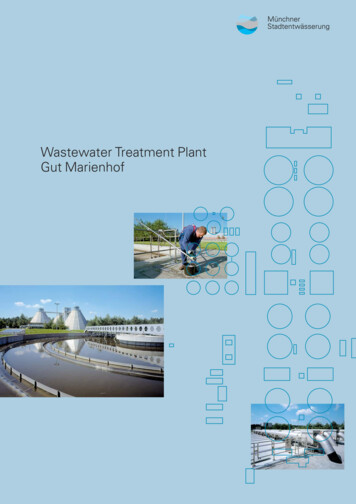
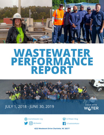
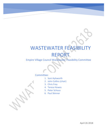
UG KCK Wolcott WWTP Preliminary Design ReportIntroduction1 Introduction1.1 BackgroundThe Wolcott Wastewater Treatment Plant (WWTP) is owned and operated by the UnifiedGovernment of Wyandotte County and Kansas City, Kansas (UG). The Wolcott WWTP islocated within the Connor Creek Basin in the northwestern most reach of UG’s service area(see Figure 1-1). The Plant is west of I-435 and north of Wolcott Drive. The legal description isNE¼, Section 12, Township 10 South, Range 23 East.1.1.1 Previous Reports and StudiesThe existing Wolcott WWTP and its respective service area has been the focus of multiplereports and studies performed for the UG. These studies were completed to aide UG indetermining the existing capacity and projected growth within the Wolcott service area. Thosereports and studies include the following: Wolcott Wastewater Treatment Plant Design Memorandum Phase I by Delich Roth &Goodwillie, P.A. Engineers – September 2007Wolcott Wastewater Treatment Plant Capacity Evaluation Report by HDR Engineering –January 2014Basins West of Muncie Creek Wastewater Master Plan by HDR Engineering – January2015Integrated Overflow Control Plan (IOCP) Draft SSO Characterization Report – August2015The 2007 WWTP Design Memorandum, prepared by DR&G, identified the planning information,flow and loading assumptions and a description of the original package WWTP. The informationdeveloped as part of the design memorandum was to be utilized in the detailed design for theinstallation of the package facility.The 2014 WWTP Capacity Evaluation Study, prepared by HDR, evaluated the existing planthydraulics and process loadings; identified the unit process in which excess capacity orhydraulic deficiencies existed; recommended improvements to remove hydraulic deficiencies;and presented conceptual cost estimates for implementing the recommended improvements.The 2015 Wastewater Master Plan, by HDR, evaluated the projected impacts of future growthover a twenty-year planning period on the existing UG collection system and treatment plantslocated within the UG service area basins west of Muncie Creek. The Master Plan included anevaluation of improvement alternatives and resulted in a 20-year Capital Improvements Plan(CIP) for the Project Area. The Wolcott WWTP Expansion Project and the PS 50 RerouteProject were two projects identified in the CIP. The PS 50 Reroute Project will necessitate theexpansion of the Wolcott WWTP. The Wolcott Expansion Project is the focus of this PreliminaryDesign Report.The Separate Sewer System (SSS) Characterization Report was completed in August 2015 aspart of the overall Integrated Overflow Control Plan (IOCP). The system characterization1-1
UG KCK Wolcott WWTP Preliminary Design ReportIntroductiondocumented the existing SSS components within the UG service area and the performanceduring dry and wet weather. The Report included an analysis of existing data and fieldinvestigation reports, and monitoring and modeling of the SSS to better understand how thesystem responds to various wet weather events and the characteristics of any overflows. TheReport established the baseline conditions that will be used to assess the effectiveness of theimplemented IOCP. The IOCP is scheduled to be submitted to the United States EnvironmentalProtection Agency (USEPA) in September 2016.1-2
Wolcott WWTPnnorQ3#*PS- 70HONEYCREEKek#*ouRiriISLANDCREEKC reMis sPS- 16ISLANDCREEKTRIBUTARYCoPS- 66#*verPOMEROYCREEKPS- 50#*PS- 67#*PS- 41PS- 63#*PS- 76#*CONNORCREEKPIPERCREEK#*MARSHALLCREEKPS- 15Mu#*n cieCre erSpringsLITTLE TURKEYTRIBUTARYNORTHLITTLETURKEYCREEK NORTHPS- 64kPS- 65MILLCREEKEdwardsvilleGRINTERCREEKLITTLE TURKEYTRIBUTARYSOUTHBETTSCREEKLITTLE TURKEYCREEKSOUTHPS- 44#*KPS- 33sRan s a3#*QTIMMONSCREEKi v erWWTP 14PS- 06#*Q3Plant 20 WWTPMORRISCREEKTOOLEYCREEKPS- 48#*Figure 1-1 Wolcott Wastewater Treatment Plant Project AreaCity BoundaryForce MainGravity MainQ3Treatment PlantSewer Basins¹00.51Sources: Esri, DeLorme, NAVTEQ, USGS, Intermap, iPC, NRCAN, Esri Japan, METI, EsriChinaMiles(Hong Kong), Esri (Thailand), TomTom, 2013
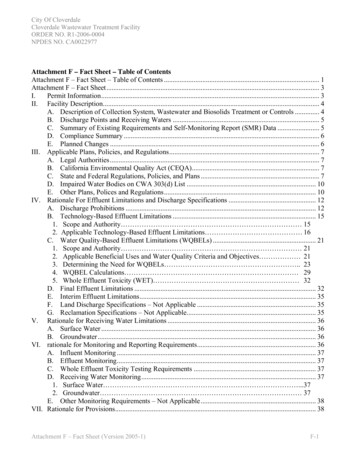
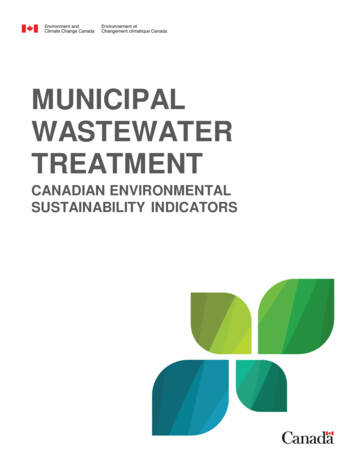
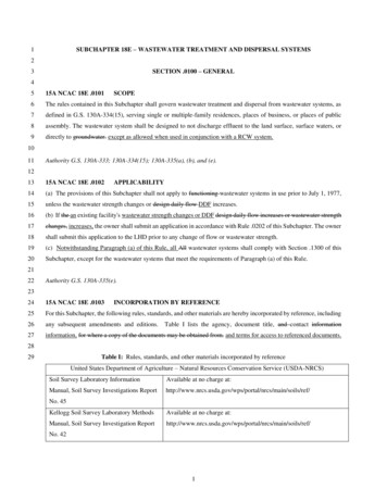
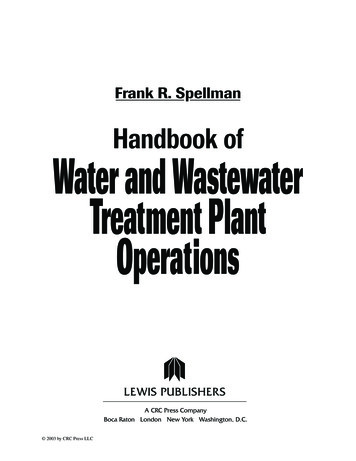
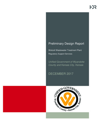
UG KCK Wolcott WWTP Preliminary Design ReportIntroduction1.1.2 Existing Wastewater Treatment Plant and Service AreaThe existing WWTP is a package treatment plant purchased and relocated from the City ofGardner, Kansas in 2007 (see Figure 1-2). The plant has a rated capacity of 0.288 MGDaverage daily flow and includes a rectangular biological treatment tank with an anaerobicchamber, anoxic chamber, aeration chamber, and an aerobic digester compartment. The plantalso includes a final clarifier, ultraviolet disinfection units and flow metering manhole. Sludge isremoved from an aerobic digester by vacuum truck for hauling and disposal. The plant effluentis discharges to the Missouri River via Connor Creek.Figure 1-2 Existing Package Wolcott WWTPFlow is conveyed to the existing Wolcott WWTP from approximately 130,000 linear feet (LF) ofsanitary sewer and seven pump stations within the Island Creek and Honey Creek basins andthe northern reaches of the Connor Creek Basin. The existing Wolcott WWTP service area isdisplayed in Figure 1-3.The two largest pump stations that convey flow to Wolcott WWTP are Pump Stations 16 and 70.Pump Station 16 conveys flow from Island Creek and Island Creek Tributary to Connor Creekthrough 13,000 feet of 8‐inch force main. Flows are then conveyed by gravity to Pump Station70. Pump Station 70 pumps flow directly to the Wolcott WWTP through 3,000 feet of 8‐inchforce main. Pump Station 70 contains two submersible pumps with a total firm capacity of 0.864MGD, effectively serving as the influent pump station for the plant.The Kansas Department of Health and Environment (KDHE) issued an NPDES permit andauthorization, effective April 1, 2013, for the Wolcott WWTP to discharge into the Missouri Rivervia Connor Creek. The NPDES permit expires on March 31, 2018. The plant permit identifies arated 0.288 MGD average daily flow but does not contain a maximum hydraulic throughput.1-4
UG KCK Wolcott WWTP Preliminary Design ReportIntroductionIn March 2015, KDHE issued a letter informing the UG of a pending change to the KansasSurface Water Quality Numeric Criteria for ammonia. The revised Kansas ammonia criteria,based on the latest national recommendations, will significantly lower maximum daily andaverage monthly limits during the next NPDES permit renewal. The letter indicated the existingPlant may require improvements and operational modifications to reliably achieve compliancewith the anticipated revised permit limitations.The Wolcott WWTP Capacity Evaluation Study, completed in January 2014, determined that theplant has capacity to treat its average daily design flow of 0.288 MGD, and a maximum 3:1throughput of 0.86 MGD. Based upon existing flow data, the plant is currently at or near itsaverage day design flow, limiting growth within the service area.As determined by the IOCP and the Master Plan efforts, substantial growth is projected to occurby 2035 in the northwestern reaches of the UG service area including the Island Creek, HoneyCreek, and Connor Creek Basins. Flows from these reaches will ultimately be treated at theWolcott WWTP. Flow from the projected growth will exceed both the dry and wet weathertreatment capacity of the Wolcott WWTP and Pump Station 70.Existing flows from the southern portion of the Connor Creek Basin, as well as flow that ispumped to Connor Creek from the Marshall Creek Basin (via Pump Station 41) and Piper CreekBasin (via Pump Station 63), are currently pumped south to Plant 20 for treatment via PumpStation 50. The alternative recommended in the IOCP and Wastewater Master Plan involvesrerouting flow from Pump Station 50 to Wolcott WWTP by gravity, allowing Pump Station 50 tobe decommissioned. The expanded Wolcott WWTP will be designed with the capacity to treatthe flows rerouted north from Pump Station 50. The Pump Station 50 reroute will reduce thepeak and average flows to Pump Station 6 and Plant 20, decreasing the magnitude of thecorresponding capacity improvements required in these facilities and the gravity systemupstream.Construction of the expanded Wolcott WWTP along with the rerouting of flows from PumpStation 50, both reduces overflows within the UG Service Area and opens up area for newdevelopment. Therefore, this Project was considered in the 2015 Master Plan as the highestpriority project in the 20‐year CIP and the plan further developed in this Report.1-5
Wolcott WWTPPS- 16ISLANDCREEKTRIBUTARYQ3#*PS- 70HONEYCREEKISLANDCREEK#*PS- 66#*POMEROYCREEKPS- 50#*PS- 67#*PS- 41PS- 63#*PS- 76#*CONNORCREEKPIPERCREEK#*MARSHALLCREEKPS- 15#*PS- 65#*#*LITTLETURKEYCREEK NORTHPS- pringsLITTLE EEKLITTLE TURKEYTRIBUTARYSOUTHBETTSCREEKLITTLE TURKEYCREEKSOUTHPS- 44PS- 33#*WWTP 14PS- 063#Q*TIMMONSCREEK#*Q3Plant 20 WWTPMORRISCREEKTOOLEYCREEKPS- 48#*Figure 1-3 Wastewater Treatment Plant Service AreasCity BoundaryQ3Treatment PlantForce MainGravity MainPlant 20 Service AreaPlant 14 Service Area¹00.51AreaIntermap, iPC, NRCAN, Esri Japan, METI, EsriSources: Esri,WolcottDeLorme, ServiceNAVTEQ, USGS,ChinaMiles(Hong Kong), Esri (Thailand), TomTom, 2013
UG KCK Wolcott WWTP Preliminary Design ReportIntroduction1.2 Project Objective and ScopeThis Preliminary Design Report is developed as part of the Regulatory Support Services Project.The purpose of the Regulatory Support Project was to enable UG to obtain regulatory approvalfor the expansion of the Wolcott WWTP by submission of an Antidegradation Review Report toKDHE.The purpose of the Project is to expand the Wolcott WWTP in to order to address futurepopulation and peak flow events and to improve the effluent quality for compliance with thephased implementation of the TMDL and the anticipated NPDES permit requirements. Thefollowing Preliminary Design Report presents the conceptual design scope, parameters,performance requirements and approach to support in the detailed design phase services. Thisreport considers three levels of nutrient removal alternatives as defined in the DraftAntidegradation Review Report: Biological Nutrient Removal (BNR):o Total nitrogen (TN) 10 mg/Lo Total phosphorus (TP) 1 mg/LEnhanced Nutrient Removal (ENR):o TN 5 mg/Lo TP 0.5 mg/LLimits of Technology (LOT):o TN 3 mg/Lo TP 0.3 mg/LThe treatment alternatives are discussed in future detail in Section 5.4.1.2.1 General RequirementsThe size of the Wolcott WWTP expansion will be a 4 MGD plant to accommodate the flowsrerouted from Pump Station 50 and the anticipated growth during the 20-year planning period.The 2015 Master Plan recommended constructing these improvements in two phases. A 2 MGDplant will initially be constructed and designed for expansion to 4 MGD when necessitated bygrowth. The plant will have the capacity to treat the current average day flows, from both theWolcott WWTP and Pump Station 50 service areas, and the projected growth likely to occurwithin the next several years. The plant will be expanded to 4 MGD when flows from futuregrowth within the service area approach the 2 MGD capacity. It is assumed that certain facilitieswill be constructed at full size to accommodate the future expansion to 4 MGD.Future expansions will be required to provide treatment for the projected ultimate growth in theWolcott WWTP service area. In an effort to establish an approximation of the treatment capacitynecessary for ultimate conditions modeling performed during the Master Plan. The projectedaverage daily flow (ADF) for the Wolcott WWTP was 17.6 MGD assuming the PS 50 wasrerouted and assuming build-out of all developments within the service area.The initial unit processes that comprise the proposed Wolcott WWTP include: Influent pump station;1-7
UG KCK Wolcott WWTP Preliminary Design ReportIntroduction Excess flow holding basin (EFHB);Headworks building;Biological treatment (BNR, ENR, or LOT);Secondary clarifiers;UV disinfection;Aerobic digesters;Solids processing building; andMaintenance and laboratory buildingThe individual unit processes are discussed in further detail in Section 5.1.2.2 Limited Geotechnical EvaluationA limited geotechnical evaluation was performed on April 24, 2017 by Alpha-Omega Geotech atthe proposed site. The limited evaluation included two (2) borings. The evaluation also took intoconsideration previous geotechnical work performed by AOG including five (5) borings.Although limited in nature, the evaluation did result in several recommendations regarding sitedevelopment and subgrade preparation details. The report indicates that additional borings andlaboratory testing may be required. The following evaluation recommendations were included: All topsoil and other deleterious material should be striped from the area of the newstructures.Imported fill material should consist of clean earthen fill free of topsoil, organics,construction debris and other deleterious material.The general fill within the structures should be engineered controlled fill placed in liftsnot exceeding 6-inches in thickness and compacted to a minimum density of 95-percentof the Standard Proctor (ASTM D698) maximum dry density at moisture content within 3-percent of the optimum moisture content.The fill material should be left to pre-load and consolidate the underlying subgrade for atleast 9 months prior to installation of structures.It may be necessary to over-excavate and construct an engineered controlled fill ofselect material consisting of properly placed and compacted crusher-run limestonebeneath the structures and at an anticipated thickness of 18 to 30 inches ( ).Based on the subsurface conditions that have been identified, Site Class E conditions(IBC 2006) may be assumed for seismic conditions.The report does note that fluctuations of the groundwater level can occur due to seasonalvariations in the amount of rainfall and other climatic factors that were not evident at the time theborings were made. The possibility of groundwater level fluctuations should be considered whendeveloping the design and construction plans for the Project.1.2.3 Site and Floodplain PermittingCoordination with the following permitting agencies will be necessary: FEMA/Unified Government FloodplainFloodplain Development PermitManager,BuyoutPropertyRestrictions,1-8
UG KCK Wolcott WWTP Preliminary Design ReportIntroduction Unified Government – Preliminary Development PlanUSACE – 401/404 applicationKansas Department of Agriculture-Division of Water Resources (KDA-DWR)Kansas Department of Wildlife, Parks, and Tourism (KDWPT)Kansas State Historic Preservation Office (KS SHPO)United States Fish and Wildlife Service (USFWS)The proposed site location is located within the floodplain fringe. A site location within thefloodplain fringe will likely require a floodplain development permit 1 but may not require a NoRise analysis or CLOMR.On October 5, 2017, on behalf of the UGKCK, HDR received approval for two jurisdictionaldeterminations for the proposed site. A standard jurisdictional determination (AJD NWK-201701430 #1) for Conner Creek and abutting wetlands were determined as regulated under Section404 CWA. A CWA permit will be needed for a new discharge outfall located within this area. Adryland jurisdictional determination (AJD NWK-2017-01430 #2) was approved for the existingsite within the property line identified in Figure 2-1. The potential aquatic resources within theproperty line were determined to be wetland depressions created in uplands incidental toconstruction activity within the meaning of 51 FR 41217, and are, therefore, non-regulatedpreamble wetlands. These jurisdictional determinations are valid for a 5-year period from thedate of the October 5th letter unless, according to the USACE, new information warrants revisionof the determination before the expiration date.1.3 Applicable Codes and StandardsA complete list of the code and standards, which will govern the design and construction of theWolcott WWTP, are presented below for each applicable discipline.1.3.1 Architectural1.International Building Code 2009 as adopted by Unified Government Chapter 8.2.International Fire Code – 2009 Edition.3.Americans with Disabilities Act (ADA) – 2010 Edition4.Occupational Safety and Health Administration (OSHA)5.Applicable ASTM Standards6.NFPA 820, Standard for Fire Protection in Wastewater Treatment and CollectionFacilities.7.NFPA 101 Life Safety Code – 2009 Edition8.Other applicable NFPA Standards1.3.2 Structural1.International Building Code 2009 as adopted by Unified Government Chapter 8.2.ACI 350-06 Code Requirements for Environmental Engineering Concrete Structuresand Commentary1UG Building Permit pg. 31-9
UG KCK Wolcott WWTP Preliminary Design ReportIntroduction3.4.5.6.7.8.9.10.ACI 350.1-10, Specification for Tightness Testing of Environmental EngineeringConcrete Structures.ACI 350.4R-04 Design Considerations for Environmental Engineering ConcreteStructuresACI 318-05 Building Code Requirements for Structural Concrete and Commentary.ACI 530-05/ASCE 5-05/TMS 402-05 Building Code Requirements for MasonryStructures.AISC Manual of Steel Construction, 13th Edition.AA ADM 1-05 Aluminum Design Manual.ASCE 7-05 Minimum Design Loads for Buildings and Other StructuresKansas Department of Transportation, - Standard Specifications for State Road andBridge Construction, 2015.1.3.31.2.3.4.5.6.7.8.Mechanical2009 International Building Code (IBC)Uniform Plumbing Code – 2009 EditionUniform Mechanical Code – 2009 EditionInternational Fire Code – 2009 EditionInternational Fuel Gas Code – 2009 EditionNational Fire Protections Association NFPA 820Various Air Moving and Conditioning Association (AMCA) StandardsVarious American Society of Heating, Refrigerating, and Air Conditioning Engineers(ASHRAE) Standards9. American National Standards Institute (ANSI)10. Sheet Metal and Air Conditioning Contractors of North America (SMACNA)11. Air Conditioning and Refrigeration Institute (ARI)12. Various American Society of Testing and Materials (ASTM) Standards13. Various National Fire Protection Association (NFPA) Standards1.3.4 Electrical1. American National Standards Institute (ANSI):a. C78.377, Specification for the Chromaticity of Solid State Lighting Products.2.ETL Testing Laboratories (ETL).3.Environmental Protection Agency (EPA):a. 40 CFR Part 60, Subpart IIII, Protection of Environment, Standards ofPerformance for New Stationary Sources, Standards for Performance forStationary Compression Ignition Internal Combustion Engines.4.Federal Communications Commission (FCC):a. Code of Federal Regulations (CFR), 47 CFR 18, Industrial, Scientific and MedicalEquipment.b. Code of Federal Regulations (CFR), 47 CFR 15, Radio Frequency Devices.5.FM Global (FM).6.Illuminating Engineering Society of North America (IESNA)7.Institute of Electrical and Electronics Engineers, Inc. (IEEE):1-10
UG KCK Wolcott WWTP Preliminary Design ReportIntroduction8.9.10.11.12.13.a. 519, Recommended Practices and Requirements for Harmonic Control inElectrical Power Systems.b. 802.3, Information Technology - Local and Metropolitan Area Networks - Part 3:Carrier Sense Multiple Access with Collision Detection (CSMA/CD) AccessMethod and Physical Layer Specifications.i. 802.3u: IEEE Standards for Local and Metropolitan Area Networks:Supplement to Carrier Sense Multiple Access with Collision Detection(CSMA/CD) Access Method and Physical Layer Specifications MediaAccess Control (MAC) Parameters, Physical Layer, Medium AttachmentUnits, and Repeater for 100 Mb/s Operation, Type 100BASE-T.ii. 802.3x: IEEE Standards for Local and Metropolitan Area Networks:Specification for 802.3 Full Duplex Operation.c. C2, National Electrical Safety Code (NESC).d. C62.41, Recommended Practice on Surge Voltages in Low-Voltage AC PowerCircuits.The International Society of Automation (ISA):a. S5.1, Instrumentation Symbols and Identification.b. S5.3, Graphic Symbols for Distributed Control/Shared Display Instrumentation,Logic and Computer Systems.c. S18.1, Annunciator Sequences and Specifications.d. S20, Standard Specification Forms for Process Measurement and ControlInstruments, Primary Elements and Control Valves.National Electrical Manufacturers Association (NEMA):a. 250, Enclosures for Electrical Equipment (1000 Volts Maximum).b. ICS 2, Industrial Control and Systems: Controllers, Contactors, and OverloadRelays Rated 600 Volts.c. ICS 6, Industrial Control and Systems: Enclosures.d. MG 1, Motors and Generators.National Fire Protection Association (NFPA):a. 70, National Electrical Code (NEC).b. 101, Life Safety Code.c. 780, Standard for the Installation of Lightning Protection Systems.d. 820, Fire Protection in Wastewater Treatment and Collection Facilities.e. 508A, Standard for Safety Industrial Control Panels.National Institute of Standards and Technology (NIST).Society of Cable Telecommunications Engineers (SCTE):a. 77, Specification for Underground Enclosure Integrity.Underwriters Laboratories, Inc. (UL).a. 467, Grounding and Bonding Equipment.b. 497B, Standard for Safety Protectors for Data Communications and Fire-AlarmCircuits.c. 508, Standard for Safety Industrial Control Equipment.d. 913, Standard for Safety, Intrinsically Safe Apparatus and Associated Apparatusfor Use in Class I, II, and III, Division 1, Hazardous (Classified) Locations.1-11
UG KCK Wolcott WWTP Preliminary Design ReportIntroduction14.15.16.e. 924, Standard for Emergency Lighting and Power Equipment.f. 778, Uninterruptible Power Systems.g. Where UL test procedures have been established for the product type, use UL orETL approved electrical equipment and provide with the UL or ETL label.h. 96A, Standard for Installation Requirements for Lightning Protection Systems.United States Department of Energy (USDOE):a. NEPA, the National Energy Policy Act.United States Department of Interior Bureau of Reclamation (USDIBR):a. Water Measurement Manual.Lighting Protection Institute (LPI)1.3.5 Other1.Great Lakes – Upper Mississippi River Board (GLUMRB) Ten States StandardsRecommended Standards for Wastewater Facilities – 2014 Edition1-12
UG KCK Wolcott WWTP Preliminary Design ReportInfluent Flow and Loadings2 Influent Flow and Loadings2.1 Existing Flows and LoadingsThe existing Wolcott influent flows and loadings were reviewed based on data received from theUG for 2010 to 2015. Several parameters were analyzed including flow, biological oxygendemand (BOD), total suspended solids (TSS), ammonia (NH3), total Kjeldahl nitrogen (TKN),and total phosphorus (TP).The 2014 Capacity Evaluation Report utilized a statistical analysis of influent flow and loadingsin determining average day (50%), maximum month (92.7%), and maximum day values(99.7%). The results of a statistical analysis are shown in Table 2-1.Table 2-1 Influent Flow and Loadings (2010 – 2015)ParameterFlow (MGD)BOD (mg/L)BOD (lb/d)TSS (mg/L)TSS (lb/d)NH3 (mg/L)NH3 (lb/d)TKN (mg/L)TKN (lb
Wolcott Wastewater Treatment Plant Design Memorandum Phase I by Delich Roth & Goodwillie, P.A. Engineers - September 2007 Wolcott Wastewater Treatment Plant Capacity Evaluation Report by HDR Engineering - January 2014 Basins West of Muncie Creek Wastewater Master Plan by HDR Engineering January - 2015