Transcription
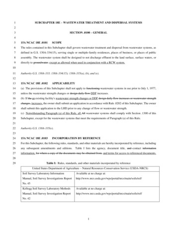
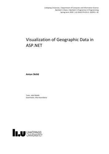
3/23/2016Presby Onsite Wastewater Treatment SystemInspection and EvaluationAdvanced Enviro-Septic , Enviro-Septic ,Simple-Septic and EnviroFin Passive WastewaterTreatment and Dispersal SystemsDennis Fogg, Don Prince, Mark Vander-HeydenPresby Technical TeamPresby Environmental20161Passive Treatment and DispersalHigh-VentLow-VentSeptic TankPresby System250,000 Systems Worldwide 2016 Presby Environmental, Inc.,All Rights Reserved21
3/23/2016Growing Worldwide3 2016 Presby Environmental, Inc.,All Rights ReservedPresby Technology – The BasicsSummary Introduced in 1995 (Enviro‐Septic)Third Party Tested and CertifiedPassive Treatment ProcessesReliable, Maintenance‐Free OperationOver 250,000 Systems in Use TodayScalable TechnologyComponents are Non‐BiodegradableH10/H20 Load Bearing Capacity2016 EnviroFinTM Wastewater Treatment System4AESESSSEFOver 100,000,000 gallons of wastewater aretreated by Presby Technology everydayusing no energy and needing no specialmaintenance or replacement parts!2
3/23/2016Presby Technology - Components5Engineered to StripOut and DigestWastewaterContaminantsEfficient Oxygen Deliveryto Active Biological Surfaces6System Sand:the “Lungs” ofthe System3
3/23/2016System Sand7Why are Too Many Fines a Problem?System Sand8 Spec‐CheckField Kit for AnalyzingFine Aggregate andSystem Sand4
3/23/2016Aerobic Bacteria are Key to SustainableTreatment in a Smaller Footprint9Presby Systems Treat Effluentto better-than SecondaryTreatment Standards with 6” ofSystem Sand Below the Pipes.Aerobic bacteria need thesame things as you 1. OxygenMaintains aerobic bacteria which digest suspended solids much more efficientlythan anaerobic bacteria. Aerobic bacteria consume the anaerobic biomat,making it permeable and creating balance within the system.2. Food and Water (with wet and dry cycles)The food and water the bacteria need exist naturally in wastewater, while wet& dry cycles stimulate the eco‐system3. Surface AreaProvides the area for bacteria to grow, strip, and digest suspended solids andother contaminantsHighly Treated Effluent Protects System SandClean System Sand surroundingAdvanced Enviro-Septic after 5years in useSide View of the First Row of aSerial System in Indiana10Treated Effluent Leaving an AESTest Site in New Zealand and Protects the Native Soil Interface5
3/23/2016Serial vs. Parallel D-box ConfigurationVenting1112 All systems require two vents (high and low) Gravity system’s roof stack is high vent , low vent at field Pumped systems require Bypass Venting or High Vent Low vent opening 3’ min. above final grade Vent diameter is 4”, (multiple or 6” dia. for large systems) Schedule 40 or equivalent PVC pipe for all vent stacks Recommend all vent joints be glued or equivalent Charcoal filters are never recommended Effluent filters block passive air flow to the roof vent andshould not be used6
3/23/2016Differential (High & Low) Venting1310'MINSUPPORTLOW VENT1’10 FT MIN.HIGH VENTFINAL GRADED-BOXDifferential or By-Pass ventingrequired for all pump systems 2016 Presby Environmental, Inc.,All Rights ReservedBy-Pass Venting for Pump Systems141. Not to be used with gravity systems.2. Invert of pipe exiting d‐box must be2” minimum above d‐box3. Use 4” Schedule 40 PVC or equal forbypass venting4. Glue all PVC joints or equivalent 2016 Presby Environmental, Inc.,All Rights Reserved7
3/23/2016Remote Venting15DISGUISEVENT IN TREEDISGUISE LOWVENT IN SHRUBSFINAL GRADELOW VENT1'MIN2" MIN OVERPLACE WASHEDSTONE AROUNDELBOW2" MIN OVERTOP OFDISTRIBUTIONBOXHIGH VENT10' MINSCREEN VENTOPENINGSDISTRIBUTION BOXAES PIPEPLACE WASHED STONEAROUND ELBOWDRILL SEVERAL 1/4"Ø HOLES AT LOW POINT OF ELBOWTO DRAIN CONDENSATION. LOW POINT MUST BE ABOVESEASONAL HIGH WATER TABLE. Detail for vent pipe runs sloping away from the bed Schedule 40 PVC for high vent stack Glue all fittings or equivalent 2016 Presby Environmental, Inc.,All Rights ReservedEnsuring Airflow through the SystemMin. 2” Dropfrom D-Box orSeptic Tank ifNo D-box isUsed16RaisedConnectionHIGHER THAN MAXIMUMLIQUID LEVEL IN PIPED-BOXLEVEL4" PVC2" MIN.MAXIMUM LIQUID LEVELThere must be a minimum 2” drop in elevation from theseptic tank or d‐box outlet invert to the AES pipe inlet invert. 2016 Presby Environmental, Inc.,All Rights Reserved8
3/23/2016Ensuring Airflow through the System17Sagging Lines Create Water TrapsWater Traps Block all air flowto the Building Roof Vent 2016 Presby Environmental, Inc.,All Rights ReservedSeptic System Inspection18Reason for Inspection: Septic System Performance Impacting Household Evidence of Effluent Breakout on Property Septic Tank Maintenance Revealed Problem Real Estate Transaction!!! Liability Favors an Unfavorable Septic SystemInspection Determination 2016 Presby Environmental, Inc.,All Rights Reserved9
3/23/2016Inspection Procedure19 Gathering Information Before Site Visit Desk Audit of Available Documents Presby System Inspection Lab Work (if required) Report Recommendations / Remediation (if required) 2016 Presby Environmental, Inc.,All Rights ReservedGathering Information20 Use NH DES Website Approval Status Designer / InstallerContact Info. E‐Files may have DesignPlan & Other Documents10
3/23/2016Gathering Information21 Acquire System Design PlanGathering Information22 Specific Details About System Commercial, Residential,Loading, Age, Maintenance, etc. Presby System Checklist Water Meter Readings (if possible) Contact Information, Address,Directions, Google Maps11
3/23/2016Desk Audit, System Verification23 Use Presby Design & Installation Manual to VerifySystem Design Meets Criteria Verify Amount of Pipe (Table A) Verify Spacing & Slope (Table B) Configuration, Venting, etc. Septic Tank Sized per NH RulesOnsite Inspection24 Take Pictures of Site before Doing Any Work A Picture is Worth A Thousand Words:Use Photographs to Document Your Work12
3/23/2016What’s Inside the Home or Business?25Take a minute to notice what is hooked intoplumbing drains headed to the septic tank Water Softener Backwash SaltwaterIs There One ?What’s Inside? (continued)26 or Are There Three !!!A SignificantImpact to theSystem thatWasn’t Plannedfor in the SepticSystem Design13
3/23/2016What’s Inside? (continued)27 Typical Garbage Disposal Organic LoadingThis Model Advertised as“SEPTIC SAFE .”Unit Dispenses a Dose ofEnzymes Automatically EachTime it is operated What’s Inside? (continued)28Is it “Septic Safe”? Consider this:Potential Increase in Pollutant Loading14
3/23/2016What’s Inside? (continued)Plumbing Issues Impacting SepticSystem 29Tank Flap StuckWide OpenIs This the Culprit?What’s Inside? (continued)30 That Led to This ?15
3/23/2016Onsite Inspection31 Use Design Plan to Locate Septic Tank, PumpChamber, D‐box and Presby FieldSeptic Tanks and VentingRoof Stack Pipe(s)321 of Six VentsSeptic TankGases HistoricallyHave BeenExpelled Via TheHouse PlumbingVent Stack16
3/23/2016Septic Tanks and Venting (continued)33Most Septic Tanks Constructed with ProvisionFor Air and Gas Movement.Septic Tanks and Venting (continued)34Old Mahogany Board BaffleReplaceable board allows for air movement17
3/23/2016Septic Tanks and Venting (cont)35Standard Concrete Board BaffleTypical Air TroughopeningEvidence ofProper liquid LevelSeptic Tanks and Venting (continued)36Standard Concrete Board BaffleBlocked Air TroughopeningEvidence ofProper liquid Level18
3/23/2016Septic Tanks and Venting (continued)37Airway to the House Vent Stack WasBlocked for 12 YearsCover Will Set RightDown on Baffle;Blocking Airway.Very Commonto See Concrete“Slag” NotChipped AwayAt Time of TankInstallationSeptic Tanks and Venting (cont)38Much Better Homeowner Did aPretty Good Job;Still a Little left toKnock Off.19
3/23/2016Septic Tanks and Venting (cont)39Inlet Area of Septic TankEvidence of HighLiquid LevelRestricting Air Flow(Scum layer wouldhave been higher)Evidence ofProper liquid LevelSeptic Tanks and Venting (cont)40Areas of Restricted Air FlowFilters RestrictAir FlowTank Cover willSet Flush WithBoard BaffleAir Trough Notchipped out20
3/23/2016Septic Tanks and Venting (cont)41Area of Restricted Air FlowTop of Tee FlushWith Bottom ofCoverOversized TeeSeptic Tanks and Presby Maze42Functioning Maze (Just Pumped)Evidence of NormalLiquid LevelSolids CollectingOn PanelsSolids CollectingOn Panels21
3/23/2016Septic Tanks / Pump Chambers43Groundwater Infiltration – System FloodingSteady Stream ofClear Water1 Pint / MinGenerates 180 gpd !That’s AnotherBedroom Design Flow !!Septic Tanks / Pump Chambers44Solids Introduced Into Pump ChamberExcess SolidsPresent In PumpChamberPump Should Only BePumping PrimaryTreated Effluent ToAny System22
3/23/2016Distribution Boxes (D-box)Many Types and Sizes (smallPlastic)45Flow Equalizersnot Needed WhenNot Splitting FlowsHigh Vent OutletPump Line InletSingle Outlet to SerialSystemDistribution Boxes (D-box) (continued)46Many Types and Sizes(Large Manifolded D‐Boxes)Note: 3 OutletsManifolded backto Feed 1 LargeD-boxSplitting Large Flowsand Feeding Multiple“Sections” UtilizingLarge ManifoldedD-Boxes23
3/23/2016Distribution Boxes (D-box) (continued)47Splitting flows(Can be problematic)Out of adjustmentThis d-box was deadlevel; the pipe on theright pitched steeperto the Presby Pipe;Raising the invert ¾” !Distribution Boxes (D-box) (continued)48Majority of Trickle Flow Exitedvia The Lower pipeEqualizers still Tendedto Mitigate theProblem24
3/23/2016Distribution Boxes (D-box) (continued)Flow “Unequalizers”You just cannot makethis stuff up !49Note positionOne Equalizer InstalledSideways; the OthersJust Tossed in the D-box.We Found Them12 Years Later!Distribution Boxes (D-box) (continued)50Flow Equalizerinstalled onVent Outlet;Restricts Airflow25
3/23/2016Distribution Boxes (D-box) (continued)51D‐BoxOut ofLevelFloodedVent Pipe;RestrictedAirflowDistribution Boxes (D-box) (continued)52Disintegrating Concrete D‐Box26
3/23/2016Presby Field53 Where to dig?Digging Holes Presby Field54 Where to dig?27
3/23/2016Is it Presby Pipe?55GEO‐FLOW PipeNotice “DiagonalStriping”Advanced DrainageSystems, Inc. (ADS)is Responsible forGEO‐FLOW InstallationsPlasticMeshPresby Enviro Septic PipeIs it Presby Pipe?56GEO-FLOW PipeDiagonal “Striping”Evident28
3/23/2016Let’s Do Some Digging !57Too Much Landscaping WithoutConsideration of Design ParametersSystems Must beVented with Morethan 18 Inches ofCover Over Pipes32” Cover (no ’s Do Some Digging ! (continued)58Too Much Backfill Without Consideration ofDesign Parameters27” Cover (no vent)Note:OftenOtherwiseA GoodInstallation29
3/23/2016Let’s Do Some Digging ! (continued)59SlightDiscolorationbeyond PresbyPipesClean, Dry, NaturalColor, “System SandWell Below (2’ )Enviro PipesLet’s Do Some Digging ! (continued)60Deep TileSpade HoleTo InspectSand Aroundand Adjacentto PresbyPipes30
3/23/2016Let’s Do Some Digging ! (continued)61Deep Hole Down To Presby Pipe,Auger Further to Inspect Conditions Below PipePresby PipeAuger HoleNatural Colored“System Sand”In Depth Inspection / Rejuvenation62“Reading”the End ofthe SystemRedoxFeatureEvidence ofProlongedFlooding31
3/23/2016In Depth Inspection / Rejuvenation63Sometimes There is No Way to Know ConditionsWithout Digging Deeper More “System SandOver the Pipes ThanAnywhere Else !On site Loamy SandUnder PipesTopsoil Cover(old Leach Field)Crushed Enviro Pipe(System in Failure)Sand Fill(old Leach Field)Normal Conditions (read the cap)64Air SpaceHistoricalEvidenceFluctuating LiquidLevels32
3/23/2016Normal Conditions (read the pipe)65Skimmer Tabs(doing their Job)Air SpaceHistoricalEvidenceFluctuatingLiquid LevelsThird-Party Sieve Analysis6633
3/23/2016Evaluation & Written Report Use Checklist, Field Notes and PicturesEvaluation & Written Report6768 Offset Adapters Show Flooded Conditions for ExtendedPeriod Shallow LedgeTank, not Pumpedin 10 Years Pumper ReportsEffluent FilterClogged, LiquidLevel at Top Tank,Solids Going toField34
3/23/2016Evaluation & Written Report69 Spacing Good, Raised Connections Good, Not Enough System Sand & Cover in CertainAreasWritten Inspection Report70 Not enough System Sand in Certain Areas Black Sand atInterior ofBed IndicatesAnaerobicConditionsStill Exist35
3/23/2016Written Inspection Report71 System SandWritten Inspection Report Recommendations Recommend Rejuvenation Increasing Amount of System Sand & Coverin Areas Where it Was Lacking Removal of Effluent Filter Creating Surface Water Diversion Upslopefrom the System7236
3/23/201673Optional Inspection Port74 2016 Presby Environmental, Inc.,All Rights Reserved37
3/23/2016Online Classes, Resources, & Support75Free Technical Support 76Technical Recommendations and Phone SupportSite Visits With Training and EducationCAD DrawingsRegulatory SupportInstallation and Operation Guidance and ManualsOnsite During ConstructionPost Sale Support for the Life of the SystemPEI has a team of dedicated expertsto help you with your project!38
Advanced Enviro-Septic , Enviro-Septic , Simple-Septic and EnviroFin Passive Wastewater Treatment and Dispersal Systems Dennis Fogg, Don Prince, Mark Vander-Heyden Presby Technical Team Presby Environmental 2016 Presby Onsite Wastewater Treatment System Inspection and Evaluation 1 High-Vent Low-Vent 250,000 Systems Worldwide