Transcription
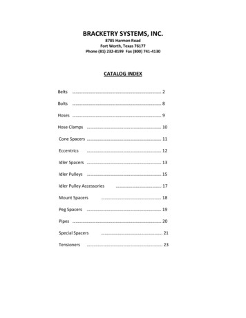
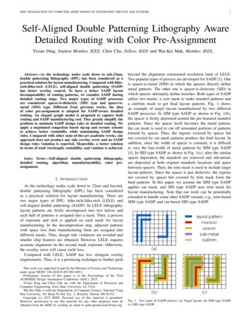
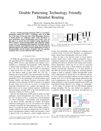
Double Patterning Technology FriendlyDetailed RoutingMinsik Cho, Yongchan Ban, and David Z. PanDept. of ECE, The University of Texas at Austin, Austin, TX 78712{thyeros, ycban, dpan}@cerc.utexas.eduAbstract— Double patterning technology (DPT) is a most likelylithography solution for 32/22nm technology nodes as of 2008due to the delay of Extreme Ultra Violet lithography. However,it should hurdle two challenges before being introduced tomass production, layout decomposition and overlay error. Inthis paper, we present the first detailed routing algorithm forDPT to improve layout decomposability and robustness againstoverlay error, by minimizing indecomposable wirelength and thenumber of stitches. Experimental results show that the proposedapproach improves the quality of layout significantly in terms ofdecomposability and the number of stitches with 3.6x speedup,compared with a current industrial DPT design flow.I. I NTRODUCTIONTo bridge the gap between current immersion lithographyand again-delayed EUV lithography, double patterning technology (DPT) receives large attention from industry and isregarded as a technically and practically viable alternativeto achieve high resolution for 32/22nm nodes [1], [7], [8],[11], [13], [14], [17]. The key idea of DPT is to decomposea single layout into two masks in order to increase pitchsize and improve depth of focus (DOF) [9], [15]. Fig. 1illustrates the concept of DPT. The increased pitch size bringsseveral advantages which enables higher resolution and betterprintability [7]: (a) the performance of Sub-Resolution AssistFeatures (SRAF) and Optical Proximity Correction (OPC)algorithms will be enhanced; (b) DPT is generic to be appliedfor poly, metal, active, and even via layers; (c) current manufacturing infrastructures (e.g., stepper) and materials (e.g.,photo-resist) can be reused without expensive modification.These advantages all make DPT as the most prominent manufacturing solution for 32/22nm nodes.However, the deployment of DPT needs to tackle two majorchallenges, layout decomposition and overlay error [1], [6],[9], [15]. As shown in Fig. 1, a layout has to be decomposed(or colored differently). Unfortunately, such decompositionis not always feasible, especially for complex 2D patternscommon in metal layers [1], [12], [13] owing to new spacingconstraints from DPT. For indecomposable cases, a simple solution is to modify the layout, which will be highly expensive.Another solution is to split one polygon into two in order toresolve decomposition conflicts, which will introduce a stitchas shown in Fig. 2 (a). However, a stitch is highly sensitive toThis work is supported in part by NSF, SRC, IBM Faculty Award, Sun, Fujitsu,Qualcomm and equipment donations from Intel.978-1-4244-2820-5/08/ 25.00 2008 IEEEMask 2ABCDELayout DecompositionMask 1Fig. 1. In DPT, one single layer can be decomposed into two masks toeffectively increase pitch size [1].overlay error, potentially causing pinching or bridging issuesas shown in Fig. 2 (b) [6], [12]. Therefore, it is important tomake a layout more decomposable with fewer stitches.There are only a few previous works on layout decomposition mainly from a mask synthesis perspective using acommercial simulator [8], design guidelines [17], and patternmatching [14]. However, all these works mainly focus on postdesign optimization, which may be too late for successfuldecomposition. Also, none of them minimize the number ofstitches systematically. Therefore, it is in great demand totake DPT into account during design time, especially detailedrouting in order to generate a highly decomposable layoutwith a small number of stitches due to the following reasons:(a) most of hard-to-decompose patterns are from complex 2Drouting wires; (b) it is the last major design optimization stepwith a comprehensive view on DPT; (c) there is considerabledesign flexibility to find reasonable tradeoff between DPT andconventional design objectives (e.g., timing, via, wirelength).In this paper, we propose the first DPT-friendly detailedrouting algorithm. The key idea behind our algorithm isto perform detailed routing and layout decomposition (orStitchStitch(a) A polygon can be splitted(b) Stitch may result in sig-to resolve a decomposition orcoloring conflict at a cost ofstitch.nificant printability degradation due to overlay errorand line-end effect.Fig. 2. The concept of a stitch is elaborated by an example in (a), and itssusceptibility to overlay error is demonstrated in (b).506
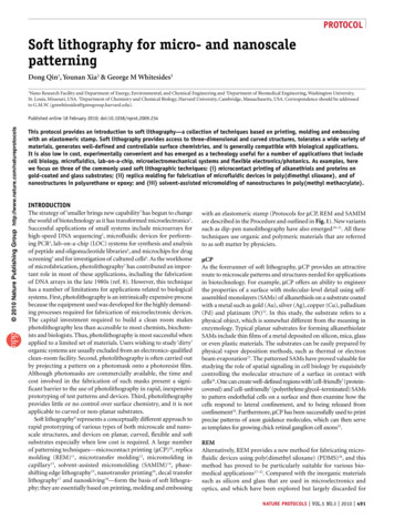
coloring) simultaneously in a correct-by-construction mannerto accomplish high layout decomposability and reduce thenumber of overlay-error-prune stitches. Therefore, our DPTfriendly detailed routing directly outputs a decomposed layoutwithout an extra time-consuming decomposition step.The rest of the paper is organized as follows. Section IIprovides preliminaries on DPT and its challenges. Section IIImotivates DPT consideration during design time. Then, wepropose our DPT-friendly detailed routing algorithm in Section IV. Experimental results are discussed in Section V,followed by conclusion in Section VI.mindpABC DADBmindp(a) mindp is required for any(b) B is only GREY-colorabletwo polygons in the samecolor.due to A, but D is BIcolorable.ABDABCDII. P RELIMINARIESA. Double Patterning Technology (DPT)The difficulty of a process technology can be describedby k1 in Rayleigh Formulae [4], k1 HP NλA where λ iswavelength of the light (currently 193nm for ArF lithography),N A is numerical aperture, and HP is minimum printablehalf-pitch. In order to print a feature in the 32nm nodewith the current single exposure infrastructure, we shouldincrease k1 above at least 0.25, which can be accomplishedby various ways including the 3rd generation immersion fluid(Refraction Index (RI) 1.8), larger lens, or Extreme UltraViolet (EUV) light source (λ 13.5nm). However, in light ofthe physical and practical limitations in the above ways, theonly feasible solution is to increase pitch size without changingminimum feature size by double patterning technology (DPT).By decomposing a layout into two masks as shown in Fig. 1,we can effectively double HP , theoretically enabling 65nmtechnology/infrastructure to print 32nm designs.As expected, however, DPT process is highly complex, asone layer needs to be patterned by two exposures and twoetching with two masks. There are several DPT lithographyprocesses; litho1-etch1-litho2-etch2 (LELE) [6], spacer typeDPT [2], and litho oriented DPT [16]. Although there aredifferences in different DPT processes, all are highly complexand involve multiple common challenges in both design andmanufacturing sides such as layout decomposition and stitchminimization, which will be discussed in Section II-B.B. Challenges in DPTThe two most important issues to deal with DPT are layoutdecomposition and overlay-error-prune stitches [12]. Layout Decomposition in DPT is to decompose (color)the original design polygons into two groups or colors(BLACK or GRAY) to decide which polygon will beplaced on which mask under the minimum double patterning spacing constraint. Stitch Minimization is another critical issue in DPT dueto the overlay error which is caused by the mismatchbetween the first patterning and the second patterning.Unfortunately, a stitch is known to be highly sensitive tothe overlay error, causing bridging or pinching. Fig. 2 (b)shows an example of a notching error due to a stitch.Due to such criticality and importance, layout decompositionand stitch minimization have been considered during mask(c) Bis only BLACKcolorable due to A, but D isBI-colorable.Fig. 3.(d) B is BI-colorable, and thecolor of C depends on that ofB.This example shows the key concepts in DPT.synthesis/manufacturing [8], [14], [17], but cannot be effectively addressed due to their high design dependency.C. DefinitionsWe explain the key definitions in DPT with Fig. 3: mindp ,BLACK-colorable, GREY-colorable, and BI-colorable. Duringlayout decomposition, as mentioned earlier, polygons will bedivided into two masks or two colors (GREY or BLACK).And, two polygons on the same mask (thus in the samecolor) should maintain minimum double patterning spacingor mindp . For example, since A and C are in BLACK, mindpis required between two as shown in Fig. 3 (a). Such mindpsometimes enforces a specific color for some polygon, if thereis an already colored polygon nearby. Consider Fig. 3 (b).Since A is already in BLACK, B should be colored as GREYnot to violate the mindp constraint, thus B is only GREYcolorable. Similarly in Fig. 3 (c), B is only BLACK-colorable.In both Fig. 3 (b) and (c), D can be colored in either way asit has enough spacing from B, so called BI-colorable.An interesting case is in Fig. 3 (d) where A and B areabutted. For this case, B is BI-colorable, because coloring B asGREY does not violate the mindp constraint (as, A and B canbe treated as one bigger polygon) and coloring B as BLACKis still fine at a cost of a stitch. The color of C depends onhow B will be colored. If B is in GREY eventually, then Cwill be BLACK-colorable (otherwise GREY-colorable).III. M OTIVATIONSIn this section, we illustrate the complexity of layoutdecomposition in Section III-A. Then, we further motivatewhy detailed routing can make significant impact on layoutdecomposition as well as the number of stitches in Section IIIB.A. Complexity of Layout DecompositionAt the first glance, layout decomposition for DPT seemsidentical to the phase-assignment problem [3], as both can507
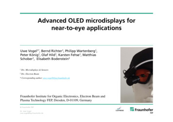
ACDEAEBDBACDBCAEBDECBCDEA(a) An example for layout decom-(b) A conflict graph for(c) The node E with(d) The node D with(e) The node A withposition for DPT is shown withfive conflicts among polygons.2-coloring can be builtfrom (a) with a doubleended queue.degree 2 is detachedand pushed into the topof the queue.degree 2 is detachedand pushed into the topof the queue.the largest degree is detached and put into thebottom of the f) The node C on the(g) The node B on the(h) The node E on the(i) The node A on the(j) However, the node A can betop of the queue is colored as BLACK andpopped out.top of the queue iscolored as GRAY andpopped out.top of the queue is colored as BLACK andpopped out.top of the queue cannotbe colored due to theconflicts with B and C.colored with BLACK and GRAYwith a stitch, resulting in successful decomposition for ) The node B with(l) The node C on the(m) The node E on the(n) The node B on the(o) The node B cannot be coloredthe largest degree is detached and put into thebottom of the queue.top of the queue is colored as BLACK andpopped out.top of the queue is colored as BLACK andpopped out.top of the queue cannotbe colored due to conflicts.due to A in GRAY and C inBLACK, resulting in decomposition failure.Fig. 4. This example describes a layout decomposition approach based on 2-coloring of a conflict graph in (a)–(j), but further shows that the same layoutcannot be decomposed by the same 2-coloring approach as shown in (k)–(o), depending on how to spill nodes. Therefore, layout decomposition for DPT isnot equivalent to but much more complex than 2-coloring, while phase-assignment is equivalent to 2-coloring [10].be formulated as a 2-coloring problem. However, there aretwo key differences. Phase-assignment is for the space between polygons, but layout decomposition for DPT is for thepolygons. More importantly, resolving a conflict in phaseassignment needs to involve layout modification (e.g., increasing spacing) [3], but not necessarily in DPT, as a polygon canbe severed into multiple polygons without altering a layout.Consider a layout in Fig. 4 (a) where five disconnectedpolygons are shown along with five conflicts in double-headedarrows. We can formulate layout decomposition of Fig. 4 (a)as a 2-coloring problem by building a corresponding conflictgraph and performing 2-coloring (BLACK or GRAY) basedon Chatin’s algorithm [5]. In Fig. 4 (b), a conflict graph forthe layout in (a) is constructed and a double-ended queue forcoloring is prepared. As in Chatin’s algorithm, a node withdegree 2 is repeatedly detached from the graph and pushedinto the top of the queue. In Fig. 4 (c), the node E is detached,which successively reduces the degree of the node D to 1,resulting in Fig. 4 (d). Since there is no node with degree 1in Fig. 4 (d), we decide to spill the node A, thus insert to thebottom of the queue as in Fig. 4 (e). Then, as both B and Chave degree 1, we can push B, then C into the queue.Once all the nodes are stored in the queue, we can popout one node from the top of the queue at a time forcoloring. As in Fig. 4 (f), we pop out C and color it asBLACK. Next, we can pop out B and color it as GRAYnot to conflict with C as in Fig. 4 (g). After several stepsincluding Fig. 4 (h), we encounter the situation in Fig. 4 (i)where A cannot be colored due to the conflicts with B andC. In a 2-coloring problem, such situation implies this graphis uncolorable, which requires layout modification in phaseassignment [10], but not necessarily in DPT. As in Fig. 4(j), layout decomposition can be completed by splitting thepolygon A into two parts at a cost of stitch on A.Let us also consider the result of not selecting A in Fig. 4(e). Although we decide to spill the node B instead of A asshown in Fig. 4 (k), it is still impossible to make the graph 2colorable as in Fig. 4 (n). However, this will make the layoutindecomposable as shown in Fig. 4 (o).As a result, differently from the phase-assignment prob-508
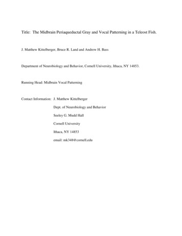
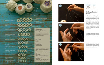
BG BG BG BG BG BG BG BG BG BG BG BG BG BGsubpath Xsubpath Ysubpath ZBG BG BG BGBG BG BG BGBG BG BGTABLE IG RID S TATE FOR DPT C OLORINGgrid eGRAY-colorableUncolorablegrid colorNearest colorBLACKGRAYNo colorBG BG BG BG BG BG BG BG BG BG BG BG BG BG(a) This example shows how to color a set of grids in a routingerror. Therefore, it is critical to consider DPT in a correct-byconstruction manner during detailed routing.path using Algorithm 1.BG BG BGBG BG BGBG BG BGBGBGBGBG BG BG(b) Thisexamplehas a potentialconflict within apath.Conflict BG BG BGIV. DPT-F RIENDLY D ETAILED ROUTINGBG BG BG(c) A simple color-(d) Some grids be-ing results in a conflict around the jog.come uncolored toresolve the conflict.In this section, we propose our DPT-friendly detailed routing algorithm. As a first step, we propose a routing pathcoloring algorithm to minimize the number of stitches inSection IV-A, which provides two key observations for DPTfriendly detailed routing in Section IV-B.BG BG BG BG BG BG BG BG BG BG BG BG BG BG BG BG BG BGBGMinimum spacingBGBGBGA. Routing Path ColoringBGMinimum spacingBGBG BG BG BG BG BG BG BG BG BG BG BG BG BG BG BG BG BG(e) Once the routing path is color, neighboring grids need to beshadowed by Algorithm 2.Fig. 5. A routing path can be efficiently colored while minimizing thenumber of stitches, and its neighboring grids are shadowed for remainingunrouted/uncolored nets.lem [3], the fact that a conflict graph is not 2-colorable doesnot guarantee the infeasibility of layout decomposition for thecorresponding layout, because some conflicts can be resolvedby stitches. The complexity of a layout decomposition for DPTwith the minimum number of stitches is unknown yet, but webelieve it is NP-hard, as there are many places for stitches.B. DPT Consideration during DesignLayout decomposition is the most critical step for DPT,as discussed in Section II, especially in metal layers due to2D patterns (while the poly layer has 1D patterns mostly).However, layout decomposition itself can be very complexand cannot be solved by a 2-coloring algorithm as discussedin Section III-A, which clearly requires design time consideration, more specifically during detailed routing. Currentindustrial effort is to first finish detailed routing, then performlayout decomposition (coloring all the polygons either inBLACK or GRAY) for DPT. If there is any uncolorablepolygon, ripup/rerouting should be performed repeatedly tofix the conflict, resulting in long design-turn-around-time [6].A detailed routing oblivious to DPT may generate highlycomplex patterns which may increase the uncolorable wirelength. Additionally, finding a decomposable layout is notsufficient for successful DPT processes; the number of stitchesshould be minimized to make a layout robust against overlayFor DPT-friendly detailed routing, it is critical to colora routed path with fewer stitches and shorter uncoloredwirelength. Hence, we introduce a two-bit variable for eachdetailed routing grid to maintain colorability which will beone of the four states in Table I. As a grid with BG can bein either BLACK or GRAY, we have to find the best color forthe grid in order to minimize the number of stitches.Algorithm 1 Coloring PathRequire: a path p1: split p into a set of colorable subpaths by the BG state2: for each path t S do3:for each ordered grid d t do4:if d.state BG then5:Color d as GRAY6:else if d.state BG then7:Color d as BLACK8:end if9:end for10:for each ordered grid d t do11:if d.state BG then12:Color d with the nearest color13:end if14:end for15: end for16: for each ordered grid d p do17:for each grid x whose distance from d mindp do18:if d.state x.state and both colored and anyuncolored grid or stitch exists between d and x then19:Uncolor x20:end if21:end for22: end for23: Color Shadow(p)509
Algorithm 2 Color ShadowRequire: A path p1: for each ordered grid d p do2:for each grid x whose distance from d mindp do3:if x / p then4:if d is in BLACK then5:if x.state BG then6:x.state BG7:else if x.state BG then8:x.state BG9:end if10:else if d is in GRAY then11:if x.state BG then12:x.state BG13:else if x.state BG then14:x.state BG15:end if16:end if17:end if18:end for19: end forOur coloring algorithm for a routing path is proposed inAlgorithm 1. To reduce the problem size, we slice a path intomultiple subpaths in line 1, if there is any grid in the BG state.Next, we color grids in either the BG or BG state, as they havea single option in lines 2–9. For remaining grids which are inthe BG state, we color each one with the nearest color alongthe corresponding subpath in lines 10–15. Since there can bewithin-path conflicts, we also perform post-processing in line16–22. Once a path is colored, we shadow around the pathin line 23, which is described in Algorithm 2, to update thestates of nearby grids. We visit grids which are within mindpdistance from the path in order to update their colorability.Assume that a routing path with 14 uncolored grids atvarious states as shown in Fig. 5 (a). We begin by splittingthe path into three subpaths, X, Y, and Z, as in line 1 ofAlgorithm 1. For each subpath, we first color grids in the BGor BG state. Then, we color remaining grids in the BG state,by identifying the nearest color within the same subpath, asshown by the arrows in Fig. 5 (a). When a subpath consistsof only grids in the BG state like subpath Z, we color themrandomly. Finally, we assemble subpaths and grids in the BGstate into one colored path.For some case, there can be conflicts within a path. ConsiderFig. 5 (c) where there is a jog. If we color the path in Fig. 5Algorithm 3 DPT-Friendly Detailed RoutingRequire: A set of blockages B, a set of nets N1: layout decomposition and color shadowing of B2: for each net n N do3:s source grid of n4:t target grid of n5:A priority queue Q {s}6:while Q is not empty do7:x dequeue from Q8:if x t then9:break10:end if11:for each adjacent grid d of x do12:cost x.cost 1 A cost //unit wirelength is 113:if x.state BG and d.state BG then14:cost α//to discourage a stitch15:else if x.state BG and d.state BG then16:cost α//to discourage a stitch17:else if d.state BG then18:cost β //to reduce uncolorable wirelength19:end if20:if x and d not on the same layer then21:cost γ//to discourage too many vias22:end if23:if d.cost cost then24:d.cost cost25:d.prev x26:enqueue d to Q27:end if28:end for29:end while30:p Backtrace from x to s of n31:Coloring Path(p)32: end for(b) as done in Fig. 5 (a), we will have Fig. 5 (c) where there isa conflict. Therefore, as the routing path is given and fixed, weneed to detect the conflict and further resolve it by uncoloringsome grids in GRAY as shown in Fig. 5 (d), which is donein lines 16–22 of Algorithm 1. Fig. 5 (e) shows the states ofnearby grids after color shadowing. Note that a grid which isclose to both BLACK and GREY becomes in the BG state.We can make two observations with the example in Fig. 5:(a) having a grid in the BG state on a path will result inlayout decomposition failure; (b) having two grids in the BGand BG states adjacent along a path will result in a stitch.B. Detailed Routing AlgorithmTABLE IIL OOKUP TABLE FOR DPT ROUTINGcase current grid state next grid statepenalty1BGBGα (stitch)2BGBGα (stitch)3any stateBGβ (uncolorable)According to the observations in Section IV-A, we will penalize three cases in Table II during detailed routing as shownin Algorithm 3. In line 1, we perform layout decompositionfor existing routing blockages (e.g., pins, power/ground, clock,and so on) using Chatin’s algorithm [5] as done in Section IIIA. When we need to spill a node, we pick one correspondingto the largest polygon. Next, we perform color shadowing510
TABLE IIIP ERFORMANCE OF THE PROPOSED DPT- FRIENDLY DETAILED ROUTING ALGORITHM .design netstest1test2abarearouter wirelen(mm)viaruntime (sec)(um2 )M1 M2 sum M1-M2 router decomposition6K 15K DR LD 1.97 8.7 10.6 18991.71099.6DPFR 1.98 8.7 10.7 216 364.608K 12K DR LD 0.54 10.2 10.857120.21517.1DPFR 0.54 10.2 10.859392.90double patterningRatiosum stitcha failure(um)b via runtime stitch1191.3 1097.7513.27 21.8364.650.151.14111697.3 9210.6014.3392392.9101.0411The number of stitches.The uncolored wirelength due to irresolvable conflicts.around the colored blockages to guide detailed routing. Then,we perform a typical detailed routing algorithm based on A*search as found in line 12. However, to find a DPT-friendlypath, we modify cost from lines 13 to 22. From lines 13–16,we add α penalty to the routing cost to discourage stitchesfrom the case 1 and 2. And, in line 18, we also increase therouting cost by β to minimize the number of uncolored grids.In line 21, we can see one more penalty term γ which isto minimize the number of vias, as decomposability or stitchcount can be improved at a cost of via. Once the minimumcost path is found, we can apply Algorithm 1 as in line 31.V. E XPERIMENTAL R ESULTSWe implement our DPT-friendly routing in C and test ona 3.0 GHz Linux machine with 16G RAM. We scale down twoindustrial ASIC designs from 65nm to 32nm for evaluation.For though comparison, we prepare two detailed routing algorithms for DPT, DR LD (Detail Routing LayoutDecomposition) and DPFR (Double Patterning FriendlyRouting). For layout decomposition in DR LD, we use thesame function in Algorithm 3 (See Section IV-B). We firstrun a grid-based detailed router followed by layout decomposition in DR LD which is according to the current industrialeffort [6], but layout decomposition and detailed routing aresimultaneously performed by Algorithm 3 in DPFR.We compare DPFR and DR LD on four test designs withα 9, β 10, and γ 6 as shown in Table III,which demonstrates the effectiveness of DPFR, a simultaneouslayout decomposition and detailed routing for DPT. Withnegligible overhead in wirelength, we can improve the qualityof layouts in terms of double patterning; the number of stitchesfor every design is reduced by at least 21x and up to 92x, andthe uncolorable wirelength is at most 0.15µm while DR LDhas at best 7.75µm. Note that the uncolorable wirelength fromDPFR is due to DPT-oblivious pin locations. Via overhead is9% on average. Even though DPFR is slower than the routingportion of DR LD, DPFR is at least 3x faster considering theoverall flow. It is mainly because DR LD has to work on alarger conflict graph for the final layout decomposition.VI. C ONCLUSIONDouble patterning technology (DPT) is the current forerunner lithography solution for 32/22nm technology nodes, dueto delayed deployment of EUV for mass production. In thispaper, we present the first DPT friendly detailed routing algorithm which performs routing and layout decomposition in oneshot, in a correct-by-construction manner. Experimental resultsshow that our approach outperforms the current industrialsequential approach (routing, and then layout decomposition)by wide margin, for both quality of results and runtime. Weplan to research on DPT compatible standard cell designtechniques and DPT aware placement algorithms.R EFERENCES[1] G. E. Bailey, A. Tritchkov, J.-W. Park, L. Hong, V. Wiaux, E. Hendrickx,S. Verhaegen, P. Xie, and J. Versluijs. Double pattern EDA solutionsfor 32nm HP and beyond. In Proc. SPIE 6521, 2007.[2] C. Bencher, Y. Chen, H. Dai, W. Montgomery, and L. Hul. 22nm halfpitch patterning by cvd spacer self alignment double patterning (sadp).In Proc. of SPIE, volume 6924, 2008.[3] P. Berman, A. B. Kahng, D. Vidhani, H. Wang, and A. Zelikovsky.Optimal Phase Conflict Removal for Layout of Dark Field AlternatingPhase Shifting Masks. In Proc. Int. Symp. on Physical Design, Apr1999.[4] M. Born and E. Wolf. Principles of Optics, 6th Edision. PergamonPress, 1980.[5] G. J. Chatin. Register Allocation & Spilling via Graph Coloring. InProc. Symp. on Compiler Construction, 1982.[6] M. Drapeau, V. Wiaux, E. Hendrickx, S. Verhaegen, and T. Machida.Double Patterning Design Split Implementation and Validation for the32nm Node. In Proc. SPIE 6521, 2007.[7] J. Huckabay, W. Staud, R. Naber, A. van Oosten, P. Nikolski, S. Hsu,R. J. Socha, M. V. Dusa, and D. Flagello. Process results usingautomatic pitch decomposition and double patterning technology (DPT)at k1ef f 0.20. In Proc. SPIE 6349, 2006.[8] Y. Inazuki, N. Toyama, T. Nagai, T. Sutou, Y. Morikawa, H. Mohri,N. Hayashi, M. Drapeau, K. Lucas, and C. Cork. Decompositiondifficulty analysis for double patterning and the impact on photomaskmanufacturability. In Proc. of SPIE, volume 6925, 2008.[9] A. B. Kahng. Key Directions and a Roadmap for Electrical Design forManufacturability. In Proc. European Solid-State Circuits Conf, 2007.[10] A. B. Kahng, S. Vaya, and A. Zelikovsk. New Graph Bipartizations forDouble-Exposure, Bright Field Alternating Phase-Shift Mask Layout. InProc. Asia and South Pacific Design Automation Conf., Jan 2001.[11] Y. Ku. Lithography challenges and solution for 32nm node and beyond.In Proc. Asia and South Pacific Design Automation Conf., Jan 2008.[12] K. Lucas, C. Cork, A. Miloslavsky, G. Luk-Pat, L. Barnes, J. Hapli,J. Lewellen, G. Rollins, V. Wiaux, and S. Verhaegen. Interactions ofdouble patterning technology with wafer processing, opc and designflows. In Proc. of SPIE, volume 6924, 2008.[13] J. Park, S. Hsu, D. V. D. Broeke, J. F. Chen, M. Dusa, R. Socha, J. Finders, B. Vleeming, A. van Oosten, P. Nikolsky, V. Wiaux, E. Hendrickx,J. Bekaert, and G. Vandenberghe. Application Challenges with DoublePatterning Technology (DPT) beyond 45nm. In Proc. SPIE 6349, 2006.[14] J. Rubinstein and A. Neureuther. Post-decomposition assessment ofdouble patterning layout. In Proc. of SPIE, volume 6924, 2008.[15] A. Sezginer and B. Yenikaya. Double Patterning Technology: ProcessWindow Analysis in a Many-Dimensional Space. In Proc. SPIE 6521,2007.[16] A. Vanleenhove and D. Steenwinckel. A litho-only approach to doublepatterning. In Proc. of SPIE, volume 6521, 2007.[17] V. Wiaux, S. Verhaegen, S. Cheng, F. Iwamoto, P. Jaenen, M. Maenhoudt, T. Matsuda, S. Postnikov, and G. Vandenberghe. Split and designguidelines for double patterning. In Proc. of SPIE, volume 6924, 2008.511
number of overlay-error-prune stitches. Therefore, our DPT-friendly detailed routing directly outputs a decomposed layout without an extra time-consuming decomposition step. The rest of the paper is organized as follows. Section II provides preliminaries on DPT and its challenges. Section III motivates DPT consideration during design time. Then, we