Transcription
SAE Aero DesignAli Alqalaf, Jasem Alshammari, Dong Yang Cao,Darren Frankenberger, Steven Goettl, and John SantoroDepartment of Mechanical EngineeringApr 29, 2016
Overview IntroductionNeed Statement / Project GoalsObjectivesConstraintsQuality Function DeploymentConcept GenerationProject Proposal and Fabrication Wing Design Fuselage Design Tail Design Electronics Difficulties Flight Calculations Final Design SpecificationsModifications Cowling Vertical Stabilizers - support bar ontopFinal DesignTesting VideoBill of MaterialsConclusions2
Introduction Dr. John Tester, advisor for the NAU SAE club Build an airplane that adheres to SAE competition requirements Testing flight performance in preparation for SAE competition3
Need Statement Northern Arizona University currently does not have an operationalairplane to compete in the SAE Aero design competitionProject Goals Design and build an aircraft that adheres to the SAE Aerocompetition requirements Gain valuable knowledge in the mechanical engineering design andmanufacturing processes, specifically in airplane design4
ObjectivesObjectiveMeasurementUnits of MeasurementWeightlbfCarry a payload frompoint A to BDistanceftSmall turning radiusDistanceftCarry max payload5
Constraints Freestanding aircraft must not exceed a combined length, width and height of 175 in Aircraft must be powered by a commercially available lithium-polymer battery pack Must use a new 2015 version 1000 W power limiter provided by Neumotors.com Interior payload bay must be smooth and dimensions must be 10’’x4’’x4’’ (length, width,height) with a tolerance of 0.125” Payload must be secured to an airframe, with payload plates Airplane must land and take off within 200 ft Must complete all tasks within 180 s6
Quality Function DeploymentWeightsSizeSafetyMaterialMotorGear BoxBatteryRadioSystemInteriorDimensionAIRCRAFT DIMENSION REQUIREMENT591001009MATERIAL AND EQUIPMENT RESTRICTIONS FORREGULAR CLASS539991331AIRCRAFT SYSTEM REQUIREMENTS539391990PAYLOAD REQUIREMENTS533931309Raw 7%16%16%3%11%9%14%Rank51228674Regular Class Design RequirementsScaled7
Component CriteriaAirfoil Coefficient of Lift (max)Design Lift CoefficientCoefficient of DragLift-to-Drag RatioLift Curve Slope (max)Pitching Moment CoefficientStall QualityVertical and HorizontalStabilizers Landing Gear Configuration WeightStrengthCoefficient of DragControlStability CoefficientPitching ControlYaw ControlWeightWing Placement Configuration Fuselage Design WeightStrengthCoefficient of DragLengthWeightLoadingCoefficient of Lift (max)Coefficient of Drag (min)Lift-to-Drag RatioPayload Configuration PayloadWeightCostEase of Construction8
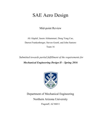
Final Design - CAD Drawing9
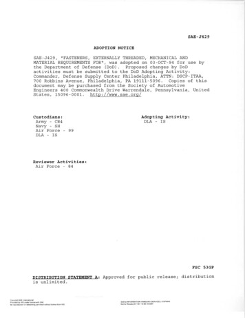
Wing Design 30 ribs 14 ailerons6 balsa dowels3D printed centerstructureRectangular sparAluminum spar10
Wing Design - Details11
Wing Design - Details12
Wing Fabrications13
Completed Wing14
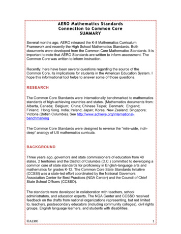
Fuselage Design15
Fuselage Fabrications16
Completed Fuselage17
Tail Design 20 ribs 12 Vertical 8 HorizontalAluminum spar18
Tail Fabrications19
Completed Tail20
Electronics Motor - AXI 5325/16 GOLD LINE Propeller - APC 18x12WE ESC/BEC-CASTLE CREATIONS Phoenix Edge 7521
Electronics Battery-Turnigy 5000mAh 6S 22.2V 20C LiPo, 12AWG EC3 Receiver-AR610 6-Channel DSMX Aircraft Receiver (SPMAR610) Servos-Extra High Torque Servo (SPMS601H)22
Circuit Diagram23
Electronics24
Flight Calculations25
Flight Calculations26
Flight Calculations27
Final Design Specifications Final Dimensions-99” Width x 55” Length x 19” Height173” Total Linear DimensionHeavy Duty Tricycle Landing Gear4” WheelsStabilator Vertical and Horizontal Control Surfaces22.2V DC Motor18x12 Propeller28
Modifications29
Final Prototype30
Flight Test31
Testing Result32
What went wrong? Connection to control surface on left side of wing failed Without the control surface the pilot could not correct themovement of the plane Resulting in loss of control of the aircraft In the next iteration, the team will improve the control surfaceconnections and establish extensive preflight inspections33
Bill of Materials34
Conclusions Dr. John Tester tasked us to construct an airplane for the SAEcompetition Constructed an RC aircraft that fulfills specified constraints andobjectives Majority of the aircraft was constructed out of birch wood and rapidprototyped components Testing revealed design flaws in the control surface connections thatwill be rectified in future iterations Gained valuable knowledge in the mechanical engineering designprocess35
Acknowledgements Dr. Srinivas Kosaraju Dr. John Tester NAU Mechanical Engineering Department Mr. Craig Howdeshell, Coconino High School Mr. Seth Lawrence36
References[1] What-When-How, “Tail design”, Conventional Tail, T-tail, Dual Tail, Triple Tail and Twin Tail. Available: whatwhen-how.com.[2] National Aeronautics and Space Administration, ”structures and materials”, aircraft background, P3-4.[3] P. J. Pritchard, Introduction to Fluid Mechanics 8th Edition. Fox and McDonald. Wiley, 2011.[4] M. H. Sadraey, Aircraft design: a systems engineering approach. Hoboken, New Jersey: Wiley, 2012.[5] “Airfoil Tools,” Airfoil Tools. [Online]. Available at: http://airfoiltools.com/. [Accessed: 2015].[6] Flight calculations. Ecalc Calc for Airplanes. [Online]. Available at: http://www.ecalc.ch/37
Questions ?38
Constraints Freestanding aircraft must not exceed a combined length, width and height of 175 in Aircraft must be powered by a commercially available lithium-polymer battery pack Must use a new 2015 version 1000 W power limiter provided by Neumotors.com Interior payload bay must be smooth and dimensions must be 10''x4''x4'' (length, width,