Transcription
Basic Analog CircuitsResistance and Ohm's LawCurrent:Potential Difference:Resistance:;;Ohm's Law:Ohm's Law RepresentationTo measure current through a component, connect an ammeter in series with it; to measure potentialdifference across a component, connect a voltmeter in parallel with it.An ammeter in series measures current through component; a voltmeter in parallel measures voltageacross component
Power:;Note: Power dissipation limits the voltage that can be applied to the input of a digitizer. The squarelaw indicates that doubling the input voltage requires the digitizer to dissipate four times more power.Voltage DividerVoltage Divider Circuit;Current DividerCurrent Divider Circuit;;Kirchhoff's Rules Loop Rule: Σ(voltage drops around a closed loop) Σ(voltage sources)Node Rule: Σ(current into a node) Σ(current out of a node)CapacitanceThe electric field between the plates of a capacitor resists changes in applied voltage. Capacitorsdecrease their resistance with frequency.Capacitance:;
Capacitance CircuitSeries:Capacitors in SeriesParallel:Capacitors in Parallel
InductanceInductance is the voltage drop across a component at a given rate of change of current through it.Mutual inductance is the voltage drop across a component at a given rate of change of current through aneighboring component. Inductors increase resistance with frequency.Inductance:Mutual Inductance:of the inductors,( is a coupling coefficient dependent on the orientation)Inductor CircuitSeries:Inductors in SeriesParallel:Inductors in ParallelAlternating CurrentPeriodically varying voltage and current are referred to as alternating (as opposed to direct): AC orDC. Alternating voltage may be described with a complex form:whereis the amplitude (magnitude of the maximum or minimum voltage) and is the angular
velocity, related to the frequency byImpedance and AdmittanceImpedance is a measure of a circuit's hindrance to current from an applied alternating voltage. It iscomprised of resistance and reactance. Reactance is the hindrance from capacitance and inductance.All are frequency dependent and are measured in units or resistance, . Admittance is the inverse ofthe impedance.Capacitive Reactance:Inductive ectronic filters remove or select specific frequency ranges or components from signals. The simplestones employ pairs of the passive components—resistors, capacitors, and inductors—we've alreadydiscussed. Recall that the impedances of capacitors and inductors (but not of resistors, which are notreactive elements) are frequency dependent:,. Notice that capacitive reactance islarge at low-frequency and small at high frequency, while inductive capacitance is the reverse. Thus, ahigh-frequency signal passing through a capacitor will be attenuated less than a low-frequency signal(high-pass filter). The reverse is true for an inductor. While resistors are not reactive, in combinationwith a reactive element, they determine the time-constant of the circuit, and therefore its frequencyresponse range.High-Pass RC FilterLow-Pass RL FilterNotice that in both of these circuits, the resistor is parallel to the power source, with one end tied toground. Reversing the positions of components, reverses the behavior (remember, that impedancebehaves like resistance, adding directly in series but inversely in parallel).
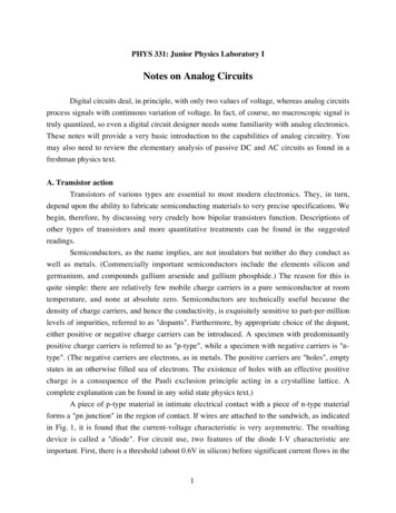
Low-Pass RC FilterHigh-Pass RL FilterA band-pass filter, in which an intermediate frequency range is able to pass, can be created bycombining a low-pass filter with a high-pass filter, or, equivalently, with an RLC circuit.DiodesDiodes are semiconductor devices which pass current in one direction.Typical diode current vs. voltage diagram. Conduction of the forward current commences at between0.2 and 0.7 volts, depending on the kind of diode.Extremely versatile passive components, diodes can regulate voltages; tune, frequency-multiply, and
mix radio-frequency circuits; emit light; switch; and perform logic in digital circuits.Simple diode-resistor rectifier.Analog Amplifier CircuitsAmplifiers increase the voltage or amplitude of signals.Input voltage increased by factor , the gain, to yield output voltageDifferential amplifiers amplify the difference between two voltages.Differential AmplifierOperational amplifiers (op-amps) employ differential amplifiers with very high input impedance andlarge gain. The high input impedance implies very little input current, so signals are not distorted, andthe large gain implies a capability of amplifying small signals.Basic Operational Amplifier
In the limit of very small signals, the two input voltage levels are approximately equal,High input resistance implies.Referring to the basic operational amplifier depicted above, we note that resistorsandform avoltage divider. If we designate the point at whichandjoin as , then we know that the voltagedrop between andis. But, here, by our assumptions,, andis at ground, so. Substituting, and solving for, we find.The minus sign indicates that the signal is inverted. The ratiois the gain factor, which can, inprinciple, range from infinitesimally small to infinitely large. Ratios greater than 1 indicateamplification; ratios less than 1 indicate attenuation.Non-inverting op-amps always amplify.Non-Inverting Operational AmplifierIn this configuration, the voltage divider is between. Therefore,and ground, so.Op-amps are also used for, among other things, buffering or isolating, comparing, summing,integrating, and differentiating signals.Signal buffering or isolating is accomplished with a voltage follower circuit. This name comes fromthe fact that in this circuit, the output voltage is the same as the input voltage. There is no amplificationor attenuation; the gain is 1. As we know, the op-amp has very large input impedance, so very littlecurrent—and, hence, very little power—is drawn from the input circuit. The input signal, therefore, islittle affected, and the output signal is the same as the input. The result is an isolation buffer: thesignal is transmitted with almost no power drawn from the circuit.
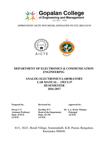
Voltage FollowerThe extremely large (unloaded, or open-loop) inherent gain of an op-amp (as much as a factor of10,000) can be exploited to indicate in a simple binary fashion when certain conditions are met at theinputs. One such application is the comparator circuit, in which the output indicates that a voltage froma source (such as a sensor of some kind) is higher or lower than a preset reference value.Simple Op-Amp ComparatorIn the diagram, the reference voltage is at the non-inverting input, while the signal comes in at theinverting input. When the magnitude of the signal exceeds that of the reference voltage, the outputgoes to it's maximum value (in practice, that of the power lines into the op-amp, here), and staysthere as long as the signal value exceeds the reference value. In this example, because the signal comesin the inverting input, the output is inverted. This is not a robust comparator—its transition is slow, sonot up to handling high frequency signal changes, and it is subject to noise fluctuations—but the idea isillustrated.A summing amplifier—or voltage adder—outputs a scaled sum of input voltages.
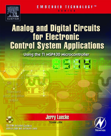
Op-Amp Summing AmplifierAgain, because,, and because. Therefore,, and. The scaled sum extends likewise with eachadditional input.Recall that the capacitance,, and the current,. Therefore, Iwill use this fact to demonstrate how an op-amp can integrate and differentiate signals.Op-Amp IntegratorBecause, and,. Thus,.Output from Square-Wave Input to an Op-Amp Integrator. We
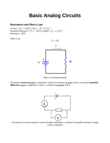
Op-Amp DifferentiatorBy reasoning similar to the integrator,. Therefore,Examples of Differentiator Behavior.
mix radio-frequency circuits; emit light; switch; and perform logic in digital circuits. Simple diode-resistor rectifier. Analog Amplifier Circuits Amplifiers increase the voltage or amplitude of signals. Input voltage increased by factor , the gain, to yield output voltage Differential amplifiers amplify the difference between two voltages.