Transcription
Published on Web 09/05/2007Single Ion-Channel Recordings Using Glass NanoporeMembranesRyan J. White,† Eric N. Ervin,† Tinglu Yang,‡ Xin Chen,‡ Susan Daniel,‡Paul S. Cremer,*,‡ and Henry S. White*,†Contribution from the Department of Chemistry, UniVersity of Utah, 315 S 1400 E, Salt LakeCity, Utah 84112, and Department of Chemistry, Texas A&M UniVersity, P.O. Box 30012,College Station, Texas 77842-3012Received May 4, 2007; E-mail: cremer@mail.chem.tamu.edu; white@chem.utah.eduAbstract: Protein ion-channel recordings using a glass nanopore (GNP) membrane as the support structurefor lipid bilayer membranes are presented. The GNP membrane is composed of a single conical-shapednanopore embedded in a 50 µm-thick glass membrane chemically modified with a 3-cyanopropyldimethylchlorosilane monolayer to produce a surface of intermediate hydrophobicity. This surface modificationresults in lipid monolayer formation on the glass surface and a lipid bilayer suspended across the smallorifice (100-400 nm-radius) of the GNP membrane, while allowing aqueous solutions to fully wet the glassnanopore. The GNP membrane/bilayer structures, which exhibit ohmic seal resistances of 70 GΩ andelectrical breakdown voltages of 0.8 V, are exceptionally stable to mechanical disturbances and havelifetimes of at least 2 weeks. These favorable characteristics result from the very small area of bilayer(10-10-10-8 cm2) that is suspended across the GNP membrane orifice. Fluorescence microscopy andvibrational sum frequency spectroscopy demonstrate that a lipid monolayer forms on the 3-cyanopropyldimethylchlorosilane modified glass surface with the lipid tails oriented toward the glass. The GNPmembrane/bilayer structure is well suited for single ion-channel recordings. Reproducible insertion of theprotein ion channel, wild-type R-hemolysin (WTRHL), and stochastic detection of a small molecule, heptakis(6-O-sulfo)-β-cyclodextrin, are demonstrated. In addition, the insertion and removal of WTRHL channelsare reproducibly controlled by applying small pressures (-100 to 350 mmHg) across the lipid bilayer. Theelectrical and mechanical stability of the bilayer, the ease of which bilayer formation is achieved, and theability to control ion-channel insertion, coupled with the small bilayer capacitance of the GNP membranebased system, provide a new and nearly optimal system for single ion-channel recordings.IntroductionFor over three decades, the insertion of transmembrane proteinchannels into supported lipid bilayers for ion-channel measurements has been an integral tool for investigating the biophysicalproperties of protein channels1-4 as well as for quantifying theinteractions of protein channels with receptor molecules.5-10Recently, application of protein ion channels supported in lipidbilayers has been proposed for designing biosensors11 and the†‡University of Utah.Texas A&M University.(1) Mayer, M.; Kriebel, J. K.; Tosteson, M. T.; Whitesides, G. M. Biophys. J.2003, 85, 2684-2695.(2) Cannon, B.; Hermansson, M.; Györke, S.; Somerharju, P.; Virtanen, J. A.;Cheng, K. H. Biophys. J. 2003, 85, 933-942.(3) Jung, Y.; Cheley, S.; Braha, O.; Bayley, H. Biochemistry 2005, 44, 89198929.(4) Miles, G.; Cheley, S.; Braha, O.; Bayley, H. Biochemistry 2001, 40, 85148522.(5) Gu, L.; Braha, O.; Conlan, S.; Cheley, S.; Bayley, H. Nature 1999, 398,686-690.(6) Gu, L.; Bayley, H. Biophys. J. 2000, 79, 1967-1975.(7) Bayley, H.; Braha, O.; Gu, L. AdV. Mater. 2000, 12, 139-142.(8) Rostovtseva, T. K.; Nestorovich, E. M.; Bezrukov, S. M. Biophys. J. 2002,82, 160-169.(9) Hirano, A.; Wakabayashi, M.; Matsuno, Y.; Sugawara, M. Biosens.Bioelectron. 2003, 18, 973-983.(10) Shin, S.; Bayley, H. J. Am. Chem. Soc. 2005, 127, 10462-10463.(11) Bayley, H.; Cremer, P. S. Nature 2001, 413, 226-230.117669J. AM. CHEM. SOC. 2007, 129, 11766-11775sequencing of DNA.12-15 Single ion-channel recordings aretraditionally performed using planar lipid bilayers supportedacross 30 to 100 µm-diameter orifices in Teflon, Delrin,polysulfone, or other suitable hydrophobic polymer-basedmembranes.16 This well-established technique possesses severaldisadvantages that are associated with the large orifice dimensions, severely limiting the development of high-throughput androbust ion-channel recording systems. In particular, the lipidbilayer supported on a large diameter orifice is sensitive topressure fluctuations, mechanical vibrations, and electricaldisturbances and is thus highly susceptible to failure (rupture)within hours or even minutes after formation. In addition,Wonderlin and co-workers also note that the lipid bilayercapacitance is a major contributor to overall system noise inion-channel recordings.17 A reduction of bilayer capacitance(12) Kasianowicz, J. J.; Brandin, E.; Branton, D.; Deamer, D. W. Proc. Natl.Acad. Sci. U.S.A. 1996, 93, 13770-13773.(13) Howorka, S.; Cheley, S.; Bayley, H. Nat. Biotechnol. 2001, 19, 636-639.(14) Akeson, M.; Branton, D.; Kasianowicz, J. J.; Brandin, E.; Deamer, D. W.Biophys. J. 1999, 77, 3227-3233.(15) Nakane, J.; Wiggin, M.; Marziali, A. Biophys. J. 2004, 87, 615-621.(16) Montal, M.; Mueller, P. Proc. Nat. Αcad. Sci. U.S.A. 1972, 69, 35613566.(17) Wonderlin, W. F.; Finkel, A.; French, R. J. Biophys. J. 1990, 58, 289297.10.1021/ja073174q CCC: 37.00 2007 American Chemical Society
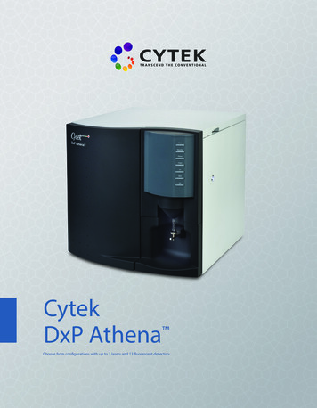
Single Ion-Channel Recordingsusing smaller diameter orifices potentially allows for increasedcurrent and temporal resolution in ion-channel recordings.17Mayer et al. reported ion-channel recordings using supportedlipid bilayers on orifices as small as 2 µm in diameter acrossan amorphous Teflon membrane.1 To the best of our knowledge,this is the smallest single orifice that has been reported to datefor ion-channel recordings.Significant improvements in lipid bilayer stability for ionchannel measurements have been achieved by sandwiching thebilayer between viscous polymeric and gel-phase materials.18,19Most recently, Gu and co-workers20 introduced a portable anddurable bilayer chip platform for single ion-channel measurements in which a lipid bilayer spanning a 100 µm-diameteraperture is sandwiched between two agarose gel layers. Theseinvestigators reported a high success rate in transporting a bilayer containing a single transmembrane protein, a bilayerbreakdown voltage of 325 mV, and a durability of 65 h withcontinuous bilayer and stochastic detection using a protein sensing unit. Bayley and co-workers reported a very similar systemthat, in addition, allows for continuous storage of a bilayercontaining a single transmembrane protein for up to 3 weeks at4 C and the capability of withstanding rigorous mechanicaldisruptions.21 It should be noted, however, that the temporalsampling responses of these ion-channel systems are limitedbecause of the need for the analyte to diffuse across the gellayers. For instance, Gu and co-workers obtained a steady-stateresponse in 40 min using 1000 µm-thick agarose layers. Otherattempts at improving bilayer stability have employed the useof tethered lipid bilayers22 and polymerizable lipid bilayers.23Herein, we report a glass nanopore (GNP) membrane supportfor ion-channel recordings that allows for the formation ofexceptionally stable bilayers with orifice areas that are a millionfold smaller than those recently reported by Gu, Bayley, andco-workers.20,21 The GNP membrane, schematically shown inFigure 1A, is a single conical nanopore embedded in a thin glassmembrane ( 50 µm), with an orifice radius as small as 10 nm.The GNP is fabricated using simple benchtop methods recentlydescribed by this laboratory.24 Because of favorable interactionsof the polar head groups of the lipid molecules and thehydrophilic glass surface, a lipid bilayer can be readily depositedat the outer surface of the unmodified GNP membrane to yielda supported bilayer across the pore orifice, as previously reportedby our laboratories.25 Fertig et al. also reported the applicationof unmodified planar glass chips for ion-channel recordings, inwhich a small aperture in the glass chip (1-50 µm) was formedby ion-track etching.26-28 The supported bilayer configuration,(18) Beddow, J. A.; Peterson, I. R.; Heptinstall, J.; Walton, D. J. Anal. Chem.2004, 76, 2261-2265.(19) Jeon, T.; Malmstadt, N.; Schmidt, J. J. J. Am. Chem. Soc. 2005, 128, 4243.(20) Shim, J. W.; Gu, L. Q. Anal. Chem. 2007, 79, 2207-2213.(21) Kang, X.; Cheley, S.; Rice-Ficht, A. C.; Bayley, H. J. Am. Chem. Soc.2007, 129, 4701-4705.(22) Cornell, B. A.; Braach-Maksvytis, V. L. B.; King, L. G.; Osman, P. D. J.;Raguse, B.; Wieczorek, L.; Pace, R. J. Nature 1997, 387, 580-583.(23) Shenoy, D. K.; Barger, W. R.; Singh, A.; Panchal, R. G.; Misakian, M.;Stanford, V. M.; Kasianowicz, J. J. Nano Lett. 2005, 5, 1181-1185.(24) Zhang, B.; Galusha, J.; Shiozawa, P. G.; Wang, G.; Bergren, A. J.; Jones,R. M.; White, R. J.; Ervin, E. N.; Cauley, C.; White, H. S. Anal. Chem.2007, 79, 4778-4787.(25) White, R. J.; Zhang, B.; Daniel, S.; Tang, J. M.; Ervin, E. N.; Cremer, P.S.; White, H. S. Langmuir 2006, 22, 10777-10783.(26) Fertig, N.; Blick, R. H.; Behrends, J. C., Biophys. J. 2002, 82, 30563062.(27) Fertig, N.; Klau, M.; George, M.; Blick, R. H.; Behrends J. C. App. Phys.Lett. 2002, 81, 4865-4867.ARTICLESFigure 1. (A) Schematic drawing of the GNP membrane (not drawn toscale); (B) schematic illustration of the spanning bilayer structure at theorifice of the GNP membrane. Modification of the glass nanopore surfacewith 3-cyanopropyldimethylchlorosilane causes the hydrophobic tail groupof the lipid to orient toward the surface. The bilayer forms only over thepore opening and corrals the transmembrane protein at the GNP orifice.however, is not ideally suited for ion-channel recordings becauseof the leakage of current through the thin water layer ( 1 nmthick) that exists between the polar head groups of the lipidsand the glass surface.25 Herein, we report methods that allowfor formation of a suspended lipid bilayer, depicted in Figure1B, in which lipid monolayers deposited on both the interiorand exterior surfaces of the GNP merge to form exceptionallystable bilayers across the GNP orifice. To successfully fabricatethis structure for a working ion-channel recording device, wehypothesized that the interior and exterior surfaces could bechemically modified to produce a glass surface that is sufficiently hydrophobic to allow deposition of a monolayer oflipid molecules with the hydrophobic tails oriented toward theglass surface, while at the same time maintaining sufficienthydrophilic surface character allowing an aqueous solution tofill the nanopore. We have discovered that deposition of3-cyanopropyldimethylchlorosilane on the GNP surface, whichcreates a silane monolayer with a terminal -CN functionality,allows for both the formation of the suspended bilayer structureshown in Figure 1B and the wetting of the nanopore by aqueoussolutions. In addition, the -CN functionality prevents proteinadsorption on glass, as initially reported by Wayment andHarris.29The GNP membrane/bilayer structure shown in Figure 1Band described later exhibits typical seal resistances of 70 GΩand can be formed over pore orifices ranging from tens ofnanometers to several micrometers on glass and quartz. Proteinion-channel recordings have been performed with GNP orificeradii as small as 100 nm (vide infra). The application of a 100nm-radius orifice results in a 106-fold reduction in the bilayerarea in comparison to conventional ion-channel measurementsand exhibits greatly improved mechanical and electrical stability.The GNP membrane platform has successfully been used insingle ion-channel recordings employing the transmembraneprotein, wild-type R-hemolysin (WTRHL) from Staphylococcusaureas, and the subsequent stochastic sensing of the smallmolecule, heptakis(6-O-sulfo)-β-cyclodextrin (s7βCD). The GNPmembrane/bilayer structure exhibits a voltage stability of 800(28) Fertig, N.; Meyer, C.; Blick, R. H.; Trautmann, C.; Behrends, J. C.; Phys.ReV. E 2004, 64 040901-1-04091-4.(29) Wayment, J. R.; Harris, J. M. Anal. Chem. 2006, 78, 7841-7849.J. AM. CHEM. SOC.9VOL. 129, NO. 38, 2007 11767
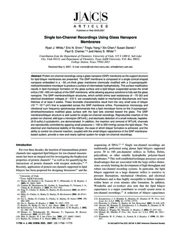
White et al.ARTICLESmV, greatly surpassing the value of 325 mV recently reportedby Gu and co-workers20 and a reported value of 460 mV forTeflon pores with diameters less than 40 µm.1 Althoughextensive stability studies have not yet been performed, the GNPmembrane/bilayer lifetime is at least 2 weeks at room temperature, and continuous stochastic detection with a WTRHL sensorunit has been achieved for at least 24 h without furtheroptimization. The GNP membrane/bilayer structure is stable tomechanical disruptions and can be transferred between differentanalyte solutions with a functioning WTRHL sensing unitremaining in place. In addition to these highly favorableproperties, we have discovered the ability to control the insertionand removal of single ion channels from the bilayer by applyingsmall pressure gradients across lipid bilayers suspended overthe GNP orifice. This intriguing discovery allows ion channelsto be sequentially, and repeatedly, inserted and removed fromthe same bilayer, an ability that may prove to be a criticalprocess component for directed insertion of proteins at differentpositions on an array of ion-channel biosensors.11Experimental SectionChemicals. KCl, K2HPO4, and KH2PO4 (Mallinckrodt) were usedas received. All aqueous solutions were prepared using water ( 18MΩ‚cm) from a Barnstead E-pure water purification system. A bufferedelectrolyte of 1.0 M KCl and 10 mM potassium phosphate buffer (PBSsolution) at a pH of 7.4 was made by dissolving appropriate amountsof each salt in ultrapure water. All references herein to PBS buffersolution refer to this solution composition. The phospholipids, 1,2dimyristoyl-sn-glycero-3-phosphocholine (DMPC), 1-palmitoyl-2-oleoyl-sn-glycero-3-phosphocholine (POPC), and 1,2-diphytanoyl-snglycero-3-phosphocholine (DPhPC) were purchased from Avanti PolarLipids (Alabaster, AL). N-(Texas Red hanolamine (Texas Red DHPE) was purchasedfrom Molecular Probes (Eugene, OR). Acetonitrile (HPLC grade, J. T.Baker) was stored over 3-Å molecular sieves. 3-Cyanopropyldimethylchlorosilane (Cl(Me)2Si(CH2)3CN) (Gelest Inc.) was used as received.Wild-type R-hemolysin, WTRHL (lyophilized powder, monomer,Sigma-Aldrich), was dissolved into 1.0 M KCl 10 mM PBS buffersolution (pH 7.4) and stored at -80 C when not in use. Heptakis(6O-sulfo)-β-cyclodextrin (s7βCD) (Fluka) was used as received.Glass Nanopore (GNP) Membranes. A benchtop method forfabricating GNP membranes was first reported in ref 25 and recentlydescribed in detail in ref 24. Briefly, the sharpened end of anelectrochemically etched 25 µm-diameter Pt wire (with half-cone angle,θ, of 10 ( 1 ) is sealed to a depth of between 25 and 75 µm into oneend of a soda-lime glass capillary that is heated to softening using aH2/air flame24 (Dagan Corporation SB16 capillaries, 1.65-mm o.d., 0.75mm i.d.; softening point 700 C; manufacturer provided composition:67.7% SiO2, 2.8% BaO, 15.6% Na2O, 5.6% CaO, 4% MgO, 1.5% B,and 0.6% K2O%).24 After cooling, the glass capillary is polished toexpose a Pt nanodisk electrode shrouded in glass. The polishing stepis performed while monitoring the electrical conductivity between thePt wire and the wetted polishing surface to determine and control thesize of the exposed disk.24 The Pt disk is then briefly electrochemicallyetched, after which the entire Pt wire is gently pulled from the glass toyield a conical-shaped nanopore. Full details of the fabrication processare presented in ref 24. A photograph of the GNP membrane platformis shown in Figure 2A. The radius of the small opening of the GNP(ri) is computed from the dc electrical ohmic resistance (R) of the GNPmeasured in a 1.0 M KCl solution at room temperature, using theexpression ri ) 19/R.25 The relative uncertainty in ri is estimated be 10%.25Glass Silanization. GNP membranes are pretreated before silanization by soaking the entire glass capillary (inside and outside) in a 0.111768 J. AM. CHEM. SOC.9VOL. 129, NO. 38, 2007Figure 2. (A) Photograph of a GNP membrane at the end of a glasscapillary (3 cm length; i.d. ) 0.75; o.d. ) 1.65 mm). A Ag/AgCl electrodeis inserted into the capillary for ion-channel measurements. (B) Schematicof the experimental setup (see text for details).M HNO3 solution for 10 min. The glass capillary is rinsed with copiousamounts of ultrapure H2O followed by CH3CN. The GNP membranesare then filled and fully immersed in a 2% v/v solution of 3-cyanopropyldimethlychlorosilane in CH3CN for 12 h to ensure surfacemodification of both the internal and external surfaces. The capillaryis rinsed sequentially with CH3CN, EtOH, and H2O followed by airdrying. Modified GNP membranes can be stored dry indefinitely forlater use in ion-channel recordings.Electrical Measurements. All electrical measurements were performed with a Dagan Chem-Clamp Low Noise potentiostat interfacedto a PC via in-house written LabVIEW (National Instruments) programs.Current-voltage (i-V) and current-time (i-t) recordings wereperformed by applying a voltage between two Ag/AgCl electrodespositioned inside and outside of the GNP capillary. The Ag/AgClelectrodes were prepared by oxidation of clean Ag wires (0.5 mmdiameter) in a saturated FeCl3 solution for 60 s. A schematicillustration of the experimental setup is presented in Figure 2B. Thevoltages reported herein are referenced to the Ag/AgCl electrodepositioned inside of the capillary.Bilayer Formation. Bilayer formation was accomplished using apainting method as described by Alvarez.39 Herein, “priming” refersto the process of bringing a plastic pipet tip containing the lipid solutionto the GNP membrane surface and the deposition of the solution ontothis surface. “Painting” refers to lightly moving a clean pipet tip (nolipid solution) across the primed GNP membrane surface to form alipid bilayer over the nanopore orifice.Following silanization, the outer surface near the pore is primed with 10 µL of a 10 mg/mL solution of a lipid dissolved in decane. Lipidsused in the ion-channel recording experiments were either POPC orDPhPC. Excess solvent is evaporated using a stream of N2, and thecapillary is filled with the PBS buffer solution (pH 7.4) or the samesolution containing a transmembrane protein. With the end of the GNP
Single Ion-Channel Recordingsmembrane fully immersed in the PBS buffer solution (pH 7.4), theouter surface is re-primed with 10 µL of the lipid/decane solution. Aclean plastic pipet tip is then lightly dragged across the exterior GNPmembrane surface to paint a lipid bilayer over the nanopore. The ioniccurrent through the GNP is continuously monitored during the paintingprocedure to determine successful bilayer formation. The suddenincrease in pore resistance from 106 to 1011 Ω is typical of successfulbilayer formation across the orifice, as subsequently demonstrated bythe measurement of ion-channel conductance values that agree withliterature values.Properly formed bilayers on the GNP membrane that are used inion-channel recordings have a breakdown voltage of 0.78 V (videinfra). Thus, the existence of a bilayer, prior to protein insertion, waschecked by application of a ( 1 V bias across the bilayer, consistentwith techniques used in conventional planar bilayer measurements.Following electrical breakdown, the bilayer was repainted and employedin ion-channel recordings. In the event that there was no voltage-inducedbreakdown, the nanopore was presumed clogged with the lipid solution.The nanopore orifice could be unclogged by repeatedly dragging a cleanpipet tip across the surface while applying (1 V until the conductancereturned to the open nanopore value. A bilayer can then often be formedon the previously clogged GNP orifice by painting with a clean pipettip.Transmembrane Pressure Control. As detailed below, a positivepressure across the membrane is required to insert transmembraneproteins into a bilayer suspended across the GNP orifice. The pressureacross the bilayer membrane was controlled by inserting the open endof the GNP into a pipet holder (DAGAN) that was connected to a 10mL gastight syringe (Hamilton), as shown in Figure 2B. The pressurewas monitored continuously using a sphygmomanometer (pressuresensing range of -100 to 300 mmHg) as shown in Figure 2B. Alltransmembrane pressures reported herein are referenced to the exterior(ambient) solution pressure. A small positive pressure inside thecapillary could also be obtained by simply sealing the end of thecapillary with a small plug of silicon rubber, allowing the Ag/AgClwire to protrude through the silicon rubber. This sealing compressesthe air and aqueous solution inside the capillary, creating a positivetransmembrane pressure.Lipid Bilayer and Monolayer Preparation for Lipid FilmStructural Analysis. Small unilamellar vesicles (SUV) were fused toglass substrates by vesicle fusion.30-32 Vesicles comprising POPC lipidsdoped with 0.1 mol % Texas Red DHPE lipids were used for thefluorescence microscopy experiments. DMPC vesicles were used forvibrational sum frequency spectroscopy (VSFS) experiments. Theappropriate composition of lipids were dissolved and mixed inchloroform and then dehydrated under vacuum for 3 h. The driedmixture was rehydrated in the PBS buffer solution (pH 7.4) andsubjected to ten freeze/thaw cycles by alternating between liquidnitrogen and a 30 C water bath. The solution was then extruded severaltimes through a polycarbonate filter to produce vesicles of uniformsize. The solution was extruded first through a filter with 100 nmdiameter pores, followed by five passes through a filter with 50 nmdiameter pores. The resultant SUVs were found to have an averagediameter of 80-90 nm as determined by light scattering using a 90PlusParticle Size Analyzer (Brookhaven Instruments Corporation).The glass coverslips used as supports for the bilayers were cleanedin 7X solution (MP Biomedicals, Aurora, OH) following establishedprocedure.33 The coverslips were then annealed in an oven at 500 Cfor 5 h to yield flat surfaces with a typical root-mean-square (rms)(30) Brian, A. A.; McConnell, H. M. Proc. Natl. Acad. Sci. 1984, 81, 61596163.(31) Groves, J. T.; Ulman, N.; Cremer, P. S.; Boxer, S. G. Langmuir 1998, 14,3347-3350.(32) Cremer, P. S.; Groves, J. T.; Kung, L. A.; Boxer, S. G. Langmuir 1999,15, 3893-3896.(33) Yang, T. L.; Jung, S. Y.; Mao, H. B.; Cremer, P. S. Anal. Chem. 2001, 73,165-169.ARTICLESroughness value of 0.13 nm over a 1 µm2 area as determined by atomicforce microscopy (AFM). Glass slides were then modified with3-cyanopropyldimethylchlorosilane in the same manner as describedabove for GNP modification. A 100 µL drop of vesicle solution wasplaced on silanized glass coverslips as well as on unmodified (bare)glass coverslips which were employed as a control. The solution wasconfined to a circular area in the center of the glass by a thinhydrophobic PDMS mold. The mold was made by crosslinking PDMSbetween two silanized glass microscope slides separated by a thin metalspacer between 200 and 400 µm thick. After crosslinking, a circularhole 1 cm in diameter was punctured through the elastomeric sheetusing a hole punch. The outer edges of the mold were trimmed to fitexactly over the glass coverslip without hanging off.The vesicle solution was incubated on the glass slides for 10 minand rinsed with copious amounts of buffer to remove any excess,unfused vesicles from the surface. Following the rinse, surfaces wheregently scratched by a pair of metal tweezers to remove lipid from asmall portion of the substrate to create a zero fluorescence baseline.These samples were subsequently rinsed before imaging under aninverted epifluorescence Nikon Eclipse TE 2000-U microscope equippedwith a Sensys CCD camera (Photometrics, Roper Scientific).Mobility Measurements. Diffusion coefficients and mobile fractionsof the lipids were measured by fluorescence recovery after photobleaching (FRAP).34 A circular patch of the bilayer containingfluorescently labeled lipids was bleached with the 568.2 nm line froma mixed gas Ar /Kr laser beam (Stabilite 2018, Spectra Physics). Abeam of 100 mW of power was directed onto the sample for less than1 s. The beam, which was sent through a 10X objective, had a fullwidth at half-maximum of 17 µm at the sample plane. The recoveryof the photobleached spot was followed as a function of time usingtime-lapse imaging under a fluorescence microscope (Nikon EclipseTE2000-U) equipped with a Sensys CCD camera (Photomatrics, RoperScientific) working in conjunction with MetaMorph software (UniversalImaging). The fluorescence intensity of the bleached spot wasdetermined after background subtraction and normalization for eachimage. The diffusion coefficient of the lipids was determined usingstandard procedures.34 Briefly a single-exponential equation was usedfit to the fluorescence recovery as a function of time, from which themobile fraction of the lipids and the half-time of recovery (t1/2) couldbe obtained. The diffusion coefficient, D, was then calculated usingthe following equation:34D)w2γ4t1/2(1)where w is the full width at half-maximum of the Gaussian profile ofthe focused beam and γ is a correction factor that depends on the bleachtime and geometry of the laser beam. In these experiments w ) 17 µmand γ ) 1.1.Vibrational Sum-Frequency Spectroscopy. VSFS measurementswere performed with a passive-active mode-locked Nd:YAG laser(PY61c, Continuum, Santa Clara, CA) equipped with a negativefeedback loop in the oscillator cavity to provide enhanced shot-to-shotstability. The 1064 nm beam has a pulse width of 21 ps and operatesat a repetition rate of 20 Hz. It is used to pump an optical parametricoscillator (OPA) stage (Laser Vision, Bellevue, WA) that generatesthe 532 nm and tunable infrared input beams (2800-4000 cm-1). TheIR and visible beams are overlapped at the sample interface withincident angles of 51 and 42 , respectively, with respect to the surfacenormal. All sum frequency spectra are taken with the SSP polarizationcombination, referring to the sum frequency, visible and infrared beams,respectively. Each data set is normalized to spectra taken from a pieceof Y-cut crystalline quartz.(34) Axelrod, D.; Koppel, D. E.; Schlessinger, J.; Elson, E.; Webb, W. W.Biophys. J. 1976, 16, 1055-1069.J. AM. CHEM. SOC.9VOL. 129, NO. 38, 2007 11769
White et al.ARTICLESResults and DiscussionSilanization of GNP Membrane and Suspended Bilayers.The suspended lipid bilayer structure depicted in Figure 1B isa consequence of the deposition of lipids on the interior andexterior surfaces of the chemically modified GNP membranewith the hydrophobic tails oriented toward the glass surface.As discussed in the Introduction, the key criterion for formationof a suspended bilayer for ion-channel recordings is that theglass surface is modified to impart sufficient hydrophobiccharacter allowing the lipid tails-down configuration, while stillmaintaining a sufficiently hydrophilic character allowing aqueous solutions to wet the nanopore. Wetting is often cited as acommon problem when working with pores of nanoscaledimensions.35After fabrication and characterization of the GNP membrane,as described in the Experimental Section, the glass surface issilanized with 3-cyanopropyldimethylchlorosilane. Because thissilane contains a single reactive Si-Cl bond, the surfacechemical modification yields a monolayer that exposes aterminal-CN group to the solution, as previously discussed inrelation to modification of functionalized GNP electrodes.36 Thewater contact angle (θc) of the modified glass surface is 55 ,which falls between angles that classify surfaces as eitherstrongly hydrophilic or hydrophobic.37 Spectroscopic measurements and fluorescence microscopy presented below explorehow chemical modification using 3-cyanopropyldimethylchlorosilane controls the structure, function, and orientation of lipidlayers at the modified glass/water interface.Following the deposition of the -CN terminated silanemonolayer on the interior and exterior surfaces of the GNPmembrane, a lipid/decane (10 mg lipid/1 mL decane) solutionis painted across the exterior surface (Experimental Section)38,39resulting in the formation of a lipid monolayer on the glasssurfaces and a lipid bilayer that is suspended across the GNPorifice. Both POPC and DPhPC were used for this purpose withsimilar results. We have found that painting the lipid/decanesolution reproducibly yields GNP membrane/bilayer seal resistances between 30 and 100 GΩ, with an average value of 71 ( 30 GΩ based on 20 independent measurements. Forinstance, Figure 3 shows i-V curves comparing the behaviorof a 150 nm-radius silanized GNP membrane prior to andfollowing the painting of a DPhPC/decane solution across theorifice. In these measurements, the GNP capillary is filled withthe PBS buffer solution (pH 7.4) and placed in a 10 mL solutionof the same composition. The ionic current is measured as afunction of the voltage scanned at 20 mV/s between internaland external Ag/AgCl electrodes. As determined from the slopesof the i-V curves, the silane modified GNP membrane has anopen pore resistance of 1.3 MΩ (labeled “Open GNP”). Thesame GNP membrane after lipid painting and bilayer formationexhibits a seal resistance of 88 GΩ (labeled “GNP/Bilayer”).The fact that a lipid bilayer is indeed suspended across the GNP(35) Riehn, R.; Austin, R. H., Anal. Chem. 2006, 78, 5933-5934.(36) Wang, G.; Zhang, B.; Wayment, J. R.; Harris, J. M.; White, H. S. J. Am.Chem. Soc. 2006, 128, 7679-7686.(37) Adamson, A. W.; Gast, A. P. Physical Chemistry of Surfaces, 6th ed.; JohnWiley & Sons: New York, 1997.(38) Mueller, P.; Tien, H. T.; Wescott, W. C.; Rudin, D. O. Circulation 1962,26, 1167-1171.(39) Alverez, O. How to Set Up A Bilayer System. In Ion Channel Reconstitution; Miller, C.,
current and temporal resolution in ion-channel recordings.17 Mayer et al. reported ion-channel recordings using supported lipid bilayers on orifices as small as 2 ím in diameter across an amorphous Teflon membrane.1 To the best of our knowledge, this is the smallest single orifice that has been reported to date for ion-channel recordings.