Transcription
JOURNAL OF APPLIED PHYSICSVOLUME 90, NUMBER 31 AUGUST 2001Dynamics of ion-ion plasmas under radio frequency biasVikas Midhaa) and Demetre J. Economoub)Plasma Processing Laboratory, Department of Chemical Engineering, University of Houston, Houston,Texas 77204-4792共Received 10 October 2000; accepted for publication 4 May 2001兲A time-dependent one-dimensional fluid model was developed to study the dynamics of a positiveion-negative ion 共ion-ion兲 plasma under the influence of a rf bias voltage. The full ion momentumand continuity equations were coupled to the Poisson equation for the electrostatic field. Specialemphasis was placed on the effect of applied bias frequency. Due to the lower temperature andgreater mass of negative ions compared to electrons, the sheath structure in ion-ion plasmas differssignificantly from that of conventional electron-ion plasmas, and shows profound structure changesas the bias frequency is varied. For low bias frequencies 共100 kHz兲, the charge distribution in thesheath is monotonic 共switching from positive to negative兲 during each half cycle. For intermediatefrequencies 共10 MHz兲, when the bias period approaches the ion transit time through the sheath,double layers form with both positive and negative charges coexisting in the sheath. For highfrequencies 共60 MHz兲, beyond the plasma frequency, plasma waves are launched from the sheathedge, and the sheath consists of multiple peaks of positive and negative charge 共multiple doublelayers兲. For a relatively large range of bias frequencies 共up to the plasma frequency兲, each electrodeis bombarded alternately by high energy positive and negative ions during a rf bias cycle. For biasfrequencies greater than the plasma frequency, however, the electrode is bombarded simultaneouslyby low energy positive and negative ions with ion energies approaching the thermal value. The ionenergy was found to increase with the applied bias potential. Also, at relatively high pressures 共20mTorr兲, the ion energy at low frequencies 共100 kHz兲 is limited by collisions. The peak ion energymay then be increased by using an intermediate bias frequency 共10 MHz兲. At lower pressures,however, the effect of collisions is mitigated while the effect of ion transit time becomes significantas the bias frequency increases. In this case, a low bias frequency 共100 s of kHz兲 is favorable forextracting high energy ions from the plasma. 2001 American Institute of Physics.关DOI: 10.1063/1.1383260兴I. INTRODUCTIONcharacterized by such weak electrostatic fields that negativeions are now able to diffuse to the walls. Thus, in contrast toelectron-ion plasmas, it is possible to extract negative ionsout of an ion-ion plasma.The electrostatic fields in an ion-ion plasma are determined by ions instead of electrons. In conventional electronion plasmas, the reason of existence of electrostatic fields isto balance wall losses of the lighter and more energetic electrons out of the plasma with those of the heavier and colderpositive ions. However, by replacing electrons with negativeions in the plasma, the mass and temperature of the negatively charged and positively charged species become comparable. Ion-ion plasmas, therefore, are characterized bymuch weaker electrostatic fields, with a plasma potential ofthe order of the ion temperature 共without external bias兲. Inthe ideal case of a positive ion-negative ion plasma in whichboth ion species have equal masses and temperatures, ion-ionplasmas are characterized by the absence of electrostaticfields and the absence of sheaths 共when no bias voltage isapplied兲. The spatial profiles of positive and negative ionscoincide throughout the length of the reactor, and both ionsare able to diffuse freely to the walls. Other salient featuresof ion-ion plasmas include:7–10 共a兲 only heavy particles participate in plasma chemistry, 共b兲 the plasma impedance canbe changed drastically by light irradiation 共negative ion pho-Ion-ion plasmas are plasmas that consist of positive andnegative ions only 共electron-free plasmas兲. In practice, asmall number of electrons can coexist, provided that thedominant negative charge carriers are negative ions; see Ref.1 for quantification. Ion-ion plasmas may be formed in theafterglow of pulsed discharges in electronegative gases.2–5Simulations of a pulsed chlorine discharge, for example,1showed that once the power is switched off, the electrondensity decays rapidly as a function of time due to diffusionand dissociative attachment with neutral molecules. In thepresence of a significant number of electrons, negative ionsremain trapped in the reactor due to the electrostatic fields,and are unable to diffuse to the walls. Therefore, while theaverage electron density drops in the afterglow, the averagenegative ion density increases due to dissociative attachment.Thus, the plasma becomes increasingly electronegative as afunction of time in the afterglow. Eventually, there is a transition to an ion-ion plasma1– 6 when the electron density andtemperature are low enough that negative ions become thedominant negative charge carrier in the plasma. This state isa兲Currently with General Electric-CRD, Schenectady, NY 12065.Author to whom all correspondence should be addressed; electronic 13/ 18.001102 2001 American Institute of PhysicsDownloaded 18 Sep 2001 to 129.7.12.23. Redistribution subject to AIP license or copyright, see http://ojps.aip.org/japo/japcr.jsp
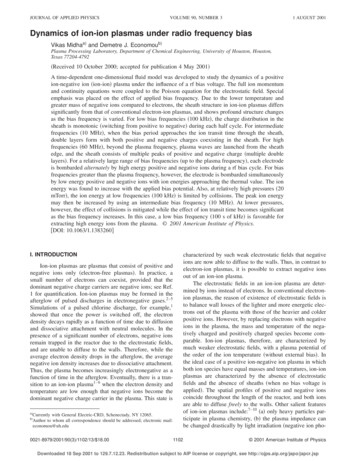
J. Appl. Phys., Vol. 90, No. 3, 1 August 2001todetachment兲 that creates electrons, 共c兲 the potential distribution in an ion-ion plasma 共without a bias or with a lowfrequency bias兲 behaves as in liquid electrolytes,11 共d兲 ionion plasma properties can be measured by a Langmuirprobe.12It is also possible to form ion-ion plasmas 共with a smallnumber of electrons兲 under steady state conditions by operating a strongly electronegative discharge at relatively highpressure.13–15 When the ratio of negative ion to electron density 共electronegativity兲 becomes greater than about 1000,electrons do not play a significant role and negative ion extraction should be possible.1,2 An ion-ion plasma 共with asmall number of electrons兲 can coexist in the same vesselwith a conventional electron-ion plasma.14 –16 The transitionbetween the two plasmas can be smooth, or double layersmay separate the two plasmas.17–20Ion-ion plasmas offer unique possibilities for plasmaetching applications. In contrast to conventional electron-ionplasmas in which negative ions remain trapped in the bulkplasma, negative ions can participate in etching in ion-ionplasmas,21–24 possibly reducing charging damage and etchprofile distortions associated with electron-ion plasmaetching.25 Ion-ion plasmas are also important in negative ionsources,26,27 the D layer of the atmosphere,28 and in dustyplasmas.10As mentioned above, an ideal 共two ions with equalmasses and temperatures兲 ion-ion plasma without an appliedexternal bias potential is characterized by the absence ofelectrostatic fields and free diffusion of ions to the walls. Theprofile of positive-ion density simply overlaps with that ofthe negative-ion density. In the presence of a bias potential,however, the positive and negative ions separate to form asheath near the electrode. In this article, the influence of anexternal rf bias on an ion-ion plasma is examined. A timedependent one-dimensional fluid model is developed whichresolves the sheath regions near the electrodes. The modelincludes the Poisson equation for the electrostatic fieldcoupled with the continuity and momentum equations for theion density and velocity, respectively. The effect of varyingthe bias frequency, bias potential and operating pressure onthe dynamics of the plasma, and the flux and energy of ionsbombarding the electrode are examined. Although the spatiotemporal dynamics of conventional electron-ion plasmashave been studied extensively,29–32 we are not aware of anypublished reports on the dynamics of ion-ion plasmas underthe influence of an external rf bias voltage.II. MODEL DEVELOPMENTA low-pressure ion-ion plasma formed in the late afterglow of a pulsed chlorine discharge is considered. The modelassumptions are outlined below.共1兲 A high degree of gas dissociation is assumed. Thus,the only ions present are Cl and Cl both at an ion temperature of 300 K.共2兲 The electron density is assumed to have decayed tolow enough values compared to the ion density 共electronegativity greater than 1000兲 so that the presence of electronsmay be completely neglected. Similarly, any electrons whichV. Midha and D. J. Economou1103FIG. 1. 共a兲 Schematic of the one-dimensional parallel plate system considered. 共b兲 Spatiotemporal evolution of the potential at base case conditionsfor a bias frequency of 100 kHz.may be generated due to capacitive coupling under the applied bias are neglected.共3兲 The parallel electrodes are assumed to be of equalarea 共one-dimensional system兲. A sinusoidal bias voltage isapplied to the driven 共left兲 electrode, while the other 共right兲electrode is grounded 关Fig. 1共a兲兴.A. Governing equationsA one-dimensional fluid model for an ion-ion plasmaunder the influence of a externally applied bias potential isdeveloped. The model consists of the following set of governing equations: The continuity equation for the positiveand negative ions is given byDownloaded 18 Sep 2001 to 129.7.12.23. Redistribution subject to AIP license or copyright, see http://ojps.aip.org/japo/japcr.jsp
1104J. Appl. Phys., Vol. 90, No. 3, 1 August 2001 ni 共 n i u i 兲 R i , t xV. Midha and D. J. Economou共1兲where n i is the ion density, u i is the ion fluid velocity, and R irepresents the rate of generation or loss of ions throughchemical reaction 共ion-ion recombination in our case, withrate coefficient of 5 10 8 cm3/s兲; i p and i n for positive and negative ions, respectively. The ion fluid velocitiesare computed by the momentum balance equations:冉 冊 冉 冊 共 n iu i 兲 共 n iu iu i 兲s iqkT i n i n i u i i ,n i E t xMiM i x共2兲where M i is the ion mass, T i is the ion temperature, i is theion-neutral collision frequency, s i is the charge number ofthe ion, and q is the value of the elementary charge. Theterms in Eq. 共2兲 共from left to right兲 represent the time rate ofchange in ion momentum or temporal inertia, spatial inertia,electrostatic force, pressure gradient, and collisional drag,respectively. The ion-neutral collision frequency was takenas proportional to the ion velocity 共low pressure constantmean free path case, see Ref. 15兲. The electrostatic field isgoverned by the Poisson equation: E q 共 n n n 兲 , x 0 p共3兲where the electric field, E, is related to the plasma potential,V, by E V/ x. Here 0 is the permittivity of free space.The potential at the driven 共left, x 0兲 electrode is assumedto be of the formV 共 x 0 兲 V b sin共 t 兲 ,共4兲where V b is the amplitude and is the frequency of theapplied bias. The potential at the grounded 共right, x L兲electrode is fixed at zero 关Fig. 1共a兲兴.The governing equations of the fluid model, therefore,consist of two continuity equations for ion densities n p andn n , two momentum equations for ion velocities u p and u nand the Poisson equation for the electrostatic field. Initialconditions were: identical positive and negative ion densityprofiles as obtained in an ion-ion plasma with equal massand temperature of the ions 共nearly parabolic if ion-ion recombination is slow兲 with a peak ion density of 1011 cm 3,and potential equal to zero everywhere. Boundary conditionsincluded zero positive and ion density on the walls.B. Linear analysis „Ref. 33 A preliminary analysis of the system of equations is instructive to estimate the time scales of important physicalprocesses. First, the time scale for ion-ion recombination fora peak ion density of 1011 cm 3 is long compared to otherphysical processes and is neglected in this analysis, i.e., R i 0. If, in addition, a constant ion collision frequency is assumed for the moment, Eqs. 共1兲 and 共2兲 may be combined toyield the following equation for ion density:冉 冊 2 共 n i u 2i 兲 2n i nis iq 共 n iE 兲 i22 t t xMi x冉 冊kT i 2 n i .M i x2共5兲This equation shows the nonlinear nature of ion transport inthe plasma. The nonlinearities are due to spatial inertia 关thirdterm from the left hand side in Eq. 共5兲兴 and electrostaticfields 共fourth term兲. Assuming an initially flat density profile(n p n n n 0 ) and small perturbations of that density, Eq. 共5兲may be linearized to give冉 冊 冉 冊 2n p npn 0q EkT i 2 n p ,i t2 tM i xM i x2共6兲for the positive-ion density and冉 冊 冉 冊 2n n nnn 0q EkT i 2 n n ,i t2 tM i xM i x2共7兲for the negative-ion density. Equations 共6兲 and 共7兲 may nowbe combined to identify two modes of propagation.共a兲 The total density (n p n n ), evolves according to therelation冉 冊 2 共 n p n n 兲 共 n p n n 兲kT i 2 共 n p n n 兲 . i t2 tMi x2共8兲For time scales greater than the characteristic collision time( c 1/ i ), temporal inertia is negligible and Eq. 共8兲 reducesto 共 n p n p 兲 2 共 n p n n 兲, D i t x2共9兲where D i is the ion diffusivity given by D i (kT i / i M i ).Therefore, over relatively long time scales, the overall density of an ion-ion plasma simply decays due to ion diffusionand is independent of the applied bias potential and frequency. Of course, over even longer time scales, ion-ion recombination 共nonlinear term兲 enters the picture.For time scales shorter than the characteristic collisiontime c , temporal inertia is dominant and Eq. 共9兲 reduces to 2 共 n p n p 兲 2 共 n p n n 兲2 c,i t2 x2共10兲where c i is the ion sonic velocity given by c i 冑kT i /M i .Equation 共10兲 represents the propagation of ion-acousticwaves. In ion-ion plasmas, ion acoustic waves propagateslowly due to the thermal motion of the ions, whereas inelectron-ion plasmas, ion-acoustic waves can also propagatedue to the presence of electrostatic fields, which are governed by the electron temperature. Therefore, the sonic velocity of ions is significantly lower in ion-ion plasmas compared to electron-ion plasmas, since the electron temperatureis normally much greater than the ion temperature.共b兲 The other mode of propagation obtained from Eqs.共6兲 and 共7兲 is the charge density (n p n n ), which propagatesaccording to the relationDownloaded 18 Sep 2001 to 129.7.12.23. Redistribution subject to AIP license or copyright, see http://ojps.aip.org/japo/japcr.jsp
J. Appl. Phys., Vol. 90, No. 3, 1 August 2001V. Midha and D. J. EconomouTABLE I. Base case parameter values used in the simulation.TABLE II. Time scales of important physical process.1011 cm 30.026 eV35.5 amu20 mTorr130 VPeak ion densityIon temperatureIon massPressureBias potential 共peak to peak兲冉 冊冉 冊 2 共 n p n n 兲 共 n p n n 兲qn 0 E 2 i2 t tM i x 共11兲For long time scales compared to c , Eq. 共11兲 reduces to共12兲where i (q/ i M i ) is the ion mobility. Equation 共12兲 givesthe rate of decay of charge density due to ion drift and iondiffusion. Since the time scales for ion drift and ion diffusionare significantly less than those associated with electrons, thecharge density decays at a much slower rate in an ion-ionplasma compared to an electron-ion plasma.For short time scales compared to c , Eq. 共11兲 reducesto冉 冊 2 共 n p n n 兲kT i 2 共 n p n n 兲2 n n ,兲共pni t2Mi x2Collision frequency i 共evaluated at u i c i 兲300 kHzFrequency of ion diffusion across discharge length(L 3.8 cm)Frequency of ion drift across sheath thickness(L S 0.2 cm)Frequency of ion diffusion across sheath thickness(L S 0.2 cm)1 kHzPlasma frequency pi 共evaluated at sheath edgen i 1010 cm 3兲kT i 2 共 n p n n 兲.Mi x2 共 n p n n 兲 E 2 共 n p n n 兲, 共 2 i n 0 兲 D i t x x21105共13兲where i (2q 2 n 0 / 0 M i ) is an ion-plasma frequency. Equation 共13兲 was derived by substituting Eq. 共3兲 for the electricfield gradient into Eqs. 共6兲 and 共7兲. Equation 共13兲 representspropagation of plasma or Langmuir waves in an ion-ionplasma. These plasma waves are similar in nature to theplasma waves in electron-ion plasmas and represent oscillations in charge density due to electrostatic fields and particleinertia. For frequencies greater than the plasma frequency,these oscillations in charge density propagate in space due tothermal motion to produce a plasma wave. For frequenciesless than the plasma frequency, the oscillations are unable topropagate in space and decay within a few Debye lengths.Since the ion-plasma frequency is significantly less than theelectron-plasma frequency, plasma waves may be present inion-ion plasmas even for relatively low-frequency perturbations.Table I shows the parameter values used as a base casein this study and Table II summarizes the important timescales which emerge from the linear analysis. The responseof an ion-ion plasma to a rf bias may be divided into different regimes based on the characteristic time scale for collisions and the ion plasma frequency. Over long time scalescompared to the collision time, the total density in the bulkplasma decays simply due to ion diffusion 关Eq. 共10兲兴 and isunaffected by the presence of the applied bias. Similarly forlong-time scales, the evolution of charge in the sheath regions will evolve simply due to ion drift and ion diffusion关Eq. 共12兲兴. For short-time scales compared to the collisiontime, the sheaths become collisionless and the time scale3 MHz75 kHz30 MHzcorresponding to the ion-plasma frequency is important. Ifthe time period of the bias is greater than the ion-plasmafrequency, the ion-plasma frequency determines the timescale over which quasineutrality is restored. Therefore, theion-plasma frequency is a measure of the transit time of theions through the sheath and may be expressed as i u av Ls冑冉 冊冉 冊qV bMi, 0V b2qn 0共14兲where u a v is a characteristic velocity of ions in the sheathand L s is a characteristic distance 共sheath thickness兲 overwhich charge separation occurs. Similarly, for time periodsless than the plasma frequency, there is insufficient time forquasineutrality to be restored and plasma waves may belaunched.Although linear analysis provides much physical insight,linear analysis cannot be used to provide quantitative information on the dynamics of ion-ion plasmas. This is due tothe following reasons:共1兲 Linear analysis is valid only for small perturbationsin the ion density with an initially uniform profile. However,the ion-ion plasma formed in the afterglow is initially nonuniform with a maximum at the center and a minimum at theelectrodes. Consequently, the ion plasma frequency is notconstant but varies spatially along the length of the reactor.The ion plasma frequency is lowest at the electrode and increase significantly towards the center.共2兲 Application of a bias potential results in large perturbations in the charge density since the magnitude of the applied potential for practical interest is several orders of magnitude greater than the ion temperature. Therefore,perturbations in the ion density are of the order of the densityitself and cannot be considered small. Also, the contributionof the electrostatic field 关fourth term from left in Eq. 共5兲兴 isnonlinear.共3兲 At low pressures, the collision frequency is not constant; a constant mean free path is a better approximation.For length scales less than the mean free path, the nonlinearity due to spatial inertia 关third term from left in Eq. 共5兲兴becomes significant. The collision frequency is a function ofthe ion velocity and the collisional drag term in the momentum equations also becomes nonlinear. For these reasons, anumerical solution of the governing Eqs. 共1兲–共3兲 is requiredto obtain quantitative results.Downloaded 18 Sep 2001 to 129.7.12.23. Redistribution subject to AIP license or copyright, see http://ojps.aip.org/japo/japcr.jsp
1106J. Appl. Phys., Vol. 90, No. 3, 1 August 2001V. Midha and D. J. EconomouIII. NUMERICAL METHODThe governing system of Eqs. 共1兲–共3兲 was discretized inspace using a finite-difference scheme based on a staggeredmesh.34 Ion densities and plasma potential were evaluated onone set of grid points while other dependent quantities 共including ion velocities, fluxes, and electric field兲 were evaluated on a staggered set of grid points. Upwind-biased finitedifference operators were employed to approximate thespatial inertia terms in the ion momentum equations. Discretization in space converted the original set of Eqs. 共1兲–共3兲into a time-dependent differential-algebraic equation 共DAE兲system. This set of DAEs was solved using LSODI, a fullyimplicit, variable order, variable time step integrator basedon backward difference formulas.35 A nonuniform mesh of301 grid points biased towards the sheaths near the electrodes was employed. Typical CPU times for each run wereabout 10–20 min on a 125 MHz Unix workstation dependingon the bias frequency. In order to obtain a periodic solution,only a few cycles were required for low bias frequencies,whereas 100s of cycles were required for high bias frequencies.IV. RESULTS AND DISCUSSIONBased on the preliminary linear analysis, the ion-ionplasma response to an applied rf bias may be divided intothree regimes depending on the frequency of the applied bias , the characteristic ion collision frequency i , and the ionplasma frequency i , the latter evaluated at the sheath edge.In all figures below, is the dimensionless bias period; for0 0.5 the bias applied to the left electrode is negative,and for 0.5 1, the bias applied to the left electrode ispositive 关Fig. 1共a兲兴. All results refer to the base case conditions 共Table I兲 unless stated otherwise.A. Low frequency regime „ Ë i Ë i At low bias frequencies, the bias period is greater thanthe characteristic time scale for collisions. Therefore, collisional drag dominates over temporal inertia and the ion velocity is in quasisteady state with respect to the local electricfield. In this regime, the bias period is also greater than thetransit time of the ions through the sheath and the ions areable to respond faithfully to the instantaneous value of applied bias without a significant phase lag.The spatiotemporal potential distribution between theplates is shown in Fig. 1共b兲 for a bias frequency of 100 kHz.In contrast to electron-ion plasmas, in which the plasma potential is the most positive potential in the system, the spatialpotential profile in ion-ion plasmas is monotonic and is symmetrically distributed between the two electrodes. This symmetry is a direct consequence of the equal masses and temperatures of the positively and negatively charged speciesassumed for this particular ion-ion plasma. Such monotonicpotential profiles are found in liquid electrolyte systemswhere the mass and temperature of positive and negativeions are comparable as well. At any instant in time, oneelectrode acquires a net positive potential with respect to thebulk plasma while the other electrode acquires an equalnegative potential. During the period 0 – 0.5 the left elec-FIG. 2. Spatiotemporal evolution of net charge at base case conditions for abias frequency of 100 kHz.trode (x 0) is negatively biased with respect to the bulkplasma while the right electrode (x L) is positively biased.Similarly during the period 0.5–1.0, the left electrode becomes positively biased while the right electrode becomesnegatively biased with respect to the bulk plasma. At this lowfrequency, the displacement current is negligible comparedto the conduction current in the bulk plasma and most of thepotential drop occurs in the sheaths near the electrodes. Thispotential profile of Fig. 1共b兲 is related to the evolution ofcharge density in the ion-ion sheaths formed at the two electrodes.Figure 2 shows the spatial profiles of the net charge density at 0.25 and 0.75. During each half of the bias cycle,positive ions are attracted towards the negatively biased electrode while negative ions are repelled. This results in theformation of a sheath with a net positive charge at the negatively biased electrode. Conversely, negative ions are attracted towards the positively biased electrode while thepositive ions are repelled. This results in the formation of asheath with a net negative charge at the positively biasedelectrode. Therefore, in contrast to electron-ion plasmas, inwhich the sheaths contain a net positive charge, the electrodesheaths in ion-ion plasmas contain equal and opposite netcharges. The polarity of the charge in each sheath is reversedduring each half cycle of the rf bias.Figures 3 and 4 show, respectively, the evolution of thepositive and negative ion-density profiles near the left electrode during the second half of a bias cycle (0.5 1). Theleft electrode was previously (0 0.5) negatively biasedwith respect to the bulk plasma, has no net bias at 0.5 andremains positively biased through the second half of thecycle. At 0.5, both positive and negative ions diffuse towards the electrode as the electrode potential is equal to theplasma potential. Since the bias period is comparable to thecharacteristic diffusion time of ions through the sheath共Table II兲, the sheath does not have sufficient time to completely collapse by 0.5 and a relatively small positivecharge persists in the sheath from the previous half cycle.The electrostatic field due to this charge is responsible forDownloaded 18 Sep 2001 to 129.7.12.23. Redistribution subject to AIP license or copyright, see http://ojps.aip.org/japo/japcr.jsp
J. Appl. Phys., Vol. 90, No. 3, 1 August 2001FIG. 3. Spatiotemporal evolution of positive ion density near left electrodeat base case conditions for a bias frequency of 100 kHz.small fronts in the ion-density profiles at the sheath edge atx 0.08 cm. Similarly, the potential in Fig. 1共b兲 is not constant for all spatial locations at 0.5 and shows the formation of minor peaks in the sheath regions 关small blips in Fig1共b兲, at 0 and 0.5兴. This effect is small at low operatingfrequencies but becomes significant at higher frequenciesand will be addressed in more detail in the following sections.After 0.5, the electrode potential increases with timeand negative ions are attracted towards the electrode whilepositive ions are repelled away from the electrode. Therefore, the sheath acquires a net negative charge. A front in thepositive-ion density profile is formed 共Fig. 3兲 which represents a competition between repulsion due to the electrostaticfield 共ion drift兲 and ion diffusion towards the electrode. Asthe electrode potential increases, this front is gradually displaced away from the electrode towards the bulk plasma resulting in an increase in the sheath width.FIG. 4. Spatiotemporal evolution of negative ion density near left electrodeat base case conditions for a bias frequency of 100 kHz.V. Midha and D. J. Economou1107FIG. 5. Ion flux at the left electrode during a bias cycle at base case conditions for a bias frequency of 100 kHz.The electrode potential decreases during the last quarterof the cycle ( 0.75– 1.0), the electrostatic field weakensand the positive-ions begin to diffuse back towards the electrode 共Fig. 3, 0.9兲. The sheath width gradually shrinks asthe magnitude of the bias potential decreases. As in the caseof 0.5, the positive and negative ions are unable to diffuseback fully to the electrode at 1.0. Therefore, the sheathdoes not fully collapse and a small negative charge persistsin the sheaths for the next cycle. The sheath at the rightelectrode also shows similar behavior but is 180 out ofphase with respect to the sheath at the left electrode.Figure 5 shows the evolution of the ion fluxes at the leftelectrode during a bias cycle. For this low operating frequency, the left electrode is bombarded alternately by positive ions and negative ions during each half of the bias cycle.This is in agreement with experimental data.36 The peak inthe negative-ion flux is slightly less than the peak in thepositive-ion flux due to continuous depletion of the plasma共no ionization in the ion-ion plasma兲. At this relatively lowoperating frequency, a significant fraction of the plasma isdepleted during the course of each half cycle. Note that thisdifference in fluxes does not imply an accumulation of a netnegative charge during the cycle. This is because the rightelectrode is bombarded by an equal flux of negative ions 共asopposed to positive ions兲 in the first half of the cycle followed by an equal flux of positive ions in the second half ofthe cycle. In other words, at any instant of the cycle, the fluxof positive ions exiting the plasma at one electrode is equalto the flux of negative ions exiting the other electrode.Figure 5 shows that the peak ion flux during a half cycleis comparable to twice the diffusion flux of the ions in theabsence of a bias. The total flux of ions integrated over a fullcycle is equivalent to the diffusion flux of ions without a biaspotential. Therefore, for low bias frequencies, the flux of ionsbombarding the electrode is independent of the magnitude ofthe applied bias potential and is limited by the ion diffusionflux. The only effect of the applied bias potential is to temporally redistribute this diffusion flux between the two elec-Downloaded 18 Sep 2001 to 129.7.12.23. Redistribution subject to AIP license or copyright, see http://ojps.aip.org/japo/japcr.jsp
1108J. Appl. Phys., Vol. 90, No. 3, 1 August 2001V. Midha and D. J. EconomouFIG. 6. Spatiotemporal evolution of the potential at base case conditions fora bias frequency of 10 MHz.FIG. 7. Spatiotemporal evolution of net charge at base case conditions for abias frequency of 10 MHz.trodes. Instead of exiting both electrodes simultaneously, thepositive ions exit only the negatively biased electrode whilethe negative ions exit only the positively biased electrodeduring each half cycle.A closer examination of Fig. 5 shows a small phase lagbetween the ion flux and the applied potential which correspo
Plasma Processing Laboratory, Department of Chemical Engineering, University of Houston, Houston, Texas 77204-4792 Received 10 October 2000; accepted for publication 4 May 2001! A time-dependent one-dimensional fluid model was developed to study the dynamics of a positive ion-negative ion ion-ion! plasma under the influence of a rf bias voltage.