Transcription
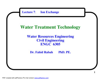
Lecture 7:Ion ExchangeWater Treatment TechnologyWater Resources EngineeringCivil EngineeringENGC 6305Dr. Fahid RabahPhD. PE.1PDF created with pdfFactory Pro trial version www.pdffactory.com
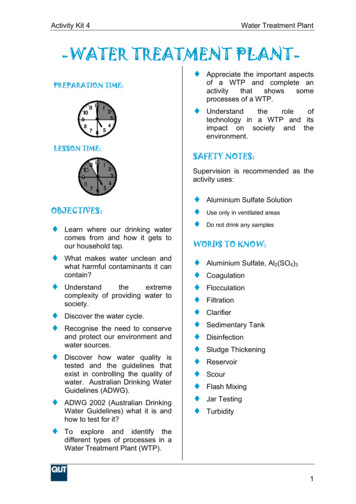
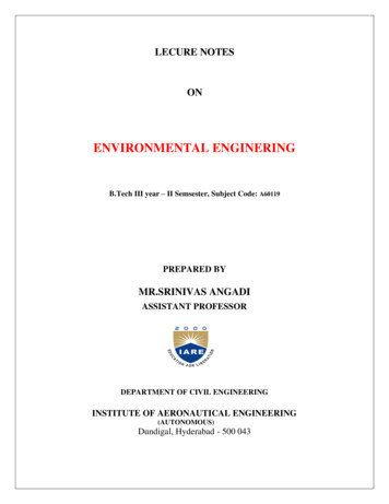
Ion Exchange1. Principles of Ion ExchangeA. Definition of Ion Exchange :- Ion exchange is a unit process in which ions of a given species aredisplaced from an insoluble material (called resin) by ions of a differentspecies in solution.- The exchanged ions have the same charge, that’s to say, positive ionsare exchanged for positive ions, for example:Na is exchanged for Mg 2 and Ca 2.OH- is exchanged for NO3- .- The exchange resin is either a naturally occurring material such aszeolite or synthetic organic material . Resins are either cationic oranionic. The resins are usually beads or granular particles having a sizeof about 0.1 to 1.0 mm. See Figures 7.1 and 7.22PDF created with pdfFactory Pro trial version www.pdffactory.com
Figure 7.1 Ion Exchange resinPDF created with pdfFactory Pro trial version www.pdffactory.com3
Figure 7.2 Ion Exchange resin4PDF created with pdfFactory Pro trial version www.pdffactory.com
Ion Exchange- Cationic resins are materials that have reactive groups that can giveup positive ions in exchange of other positive ions from the liquidphase- Anionic resins are materials that have reactive groups that can giveup negative ions in exchange of other negative ions from the liquidphase.- The exchange of ions is governed by the relative preference and thestrength of ions to replace others. The preference series for the mostcommon cations and anions is given in the next slide.- From the cation or the anion preference series, the ion in the upstreamof the series can replace or remove all the ions down stream of theseries. such as Ba 2. For example Ba 2 is able to remove all the ionslower in the series such as Na . And SO4-2 is able to remove all theions lower in the series such as OH-.5PDF created with pdfFactory Pro trial version www.pdffactory.com
Ion ExchangePreference series shows which ions exchangeFor cation exchangers:Ba 2 Pb 2 Sr 2 Ca 2 Ni 2 Cd 2 Cu 2 Co 2 Zn 2 Mg 2 Ag Cs Rb K NH4 Na H For anion exchangers:SO4-2 CLO4- I- NO3- CrO4-2 CO3-2 Br - CL- HCO- F- OH-6PDF created with pdfFactory Pro trial version www.pdffactory.com
Ion ExchangeB. Types of ion exchange resins:- Both anion and cation resins are produced from the same basic organic-polymers. They differ in the ionizable group attached to thehydrocarbon network. It is this functional group that determines thechemical behavior of the resin.Resins can be broadly classified as strong or weak acid cationexchangers or strong or weak base anion exchangers.The following are the main materials that are used as ion exchangers:- Zeolite (natural occurring mineral called greensand).- Synthetic organic polymers.Synthetic polymers are the mostly used ion exchange resins in watertreatment.7PDF created with pdfFactory Pro trial version www.pdffactory.com
Ion ExchangeC. Use of Ion Exchange in water treatment:Ion exchange is used in water treatment for the following two applications:1. Softening :The resin used for softening is called the sodium exchanger. In thisexchanger Na is changed for polyvalent cations , specially Ca 2 andMg 2. The chemical reactions of ion exchange softening is shown inthe following slide. See Figure 7.32. Demineralization:Two resins are used in demineralization the first is called the hydrogen(H ) exchanger which is used to remove positively charged ions (suchas nickel, copper, and sodium), and the second is called the hydroxyl(OH-) exchanger which is used to remove negatively charged ions suchas sulfates, nitrates, carbonates, chromates and chlorides). Thechemical reactions of ion exchange softening is shown in thefollowing slide. See Figure 7.48PDF created with pdfFactory Pro trial version www.pdffactory.com
Ion Exchange2. Ion exchange chemistry:A) Sodium cation exchange:Softening:Ca 2 2Na.RCa.R 2Na Mg 2 2Na.RMg.R 2Na Regeneration:using strong brine (NaCl)Mg. R 2NaCl2Na.R MgCl2Ca. R 2NaCl2Na.R CaCl29PDF created with pdfFactory Pro trial version www.pdffactory.com
Figure 7.3 Sodium type ion exchange resinPDF created with pdfFactory Pro trial version www.pdffactory.com10
Ion ExchangeB. Demineralization (Deionization):i) Hydrogen cation exchange:Examples:M a aH.RM.Ra aH Ca 2 2H.RNa H.RCa.R2 2H Na.R H Regeneration:using strong acidCa. R H2SO42Na. R H2SO42H.R CaSO42H.R Na2SO411PDF created with pdfFactory Pro trial version www.pdffactory.com
Ion ExchangeDemineralization (Deionization) continued:ii) Hydroxyl anion exchange:A-b bR.OHRb.A bOH-NO3- R.OHR.NO3- OH-Examples:CO3-2 2 R.OHR2.CO3-2 2OH-Regeneration: using strong base (caustic soda)R.NO3- NaOHR2.CO3-2 2NaOHR.OH NaNO32R.OH Na2CO312PDF created with pdfFactory Pro trial version www.pdffactory.com
Figure 7.4 Deionizing type ion exchange resinPDF created with pdfFactory Pro trial version www.pdffactory.com13
Ion ExchangeC. Regeneration ion exchangers:- Each resin has a limited capacity of exchanging ions.- After a certain time of operation the resin reach its maximum capacityand no further ions are removed from the liquid phase. At this point issaid to have reached the breakthrough concentration (similar toadsorption).- After reaching the breakthrough concentration of the cation or anionunder consideration, the ion exchanger tank is taken off line.- For sodium exchangers, a strong brine of NaCl is pumped in the resinbed to add the Na ions to restore the exchange capacity of the resin byreplacing the cations (Ca 2 and Mg 2) that were attached to the resinduring the operation. The strength of the brine overcomes the strengthof the bond between the cations (Ca 2 and Mg 2) and the resin.- For demineralization, a strong acid such as H2SO4 or HCl is used toregenerate the Hydrogen resin, a strong base such as caustic soda(NaOH) is used to regenerate the Hydroxyl resin.14PDF created with pdfFactory Pro trial version www.pdffactory.com
Ion Exchange3. The ion exchange system in water treatment:a) Configuration of the ion exchanger (Figure 7.5):- The main component of the ion exchanger is a cylindrical steel tank with the followingtypical dimensions:Diameter 1-2 mHeight 3-4 m (typical to the adsorption tanks)- The ion exchange bed occupies 1-3 meters of the tank height and supported from thebottom with an under drain system.- The water inters from the top (downflow) by an influent distributor piping system andapplied at the rate of 0.5 to 7 L/s.m2 .- When breakthrough is reached the tank is taken off-line and backwashed by applyingwater form the bottom upwards to remove any suspended solids.- After backwashing the regeneration solution is also pumped from the bottom upwards at the rate of 0.7 to 1.5 L/s.m2 . The same influent distributor is used to drainthe upflow backwash water and the regeneration solution ( brine, acid or base). Atthe end of the regeneration the bed is washed with clean water to remove the residualof the regeneration solution- An under drain piping system is installed at the bottom to collect the treated water, andused to pump the upflow backwash water and the regeneration solution.15PDF created with pdfFactory Pro trial version www.pdffactory.com
Ion ExchangeFigure 7.5 Typical ion exchange installation16PDF created with pdfFactory Pro trial version www.pdffactory.com
Ion Exchangeb) Pretreatment:-The influent to the ion exchanger should be filtered to remove turbidity.Dissolved Organic matter should be removed by GAC before the IE becausethe organic may coat th resin and reduce its exchange capacity.The IE is efficient for TDS less than 1000 mg/L.c) Sizing ion exchanger :- The sizing of the ion exchanger depends on the following factors:i) Contact timeii) Hydraulic loading rateiii) resin depthiv) number of columns.d) Multiple tanks Operation:- Ion exchange tanks can be operated in parallel or in series. Figures 7.6illustrates the series operation.- A minimum of two parallel carbon contactors is recommended for design.- Multiple units permit one or more units to remain in operation while one unitis taken out of service for backwashing and generation or maintenance.17PDF created with pdfFactory Pro trial version www.pdffactory.com
Figure 7.6 Ion Exchanger tanks operated in seriesPDF created with pdfFactory Pro trial version www.pdffactory.com18
Ion Exchange4. Exchange capacity of ion exchange resins:- Ion Exchange resins have a limited number of exchange site available, and thetotal solid phase concentration “q0” is termed ion exchange capacity.- For cation exchange resins, “q0” is in the range of 200 to 500 meq/100mg ofresin.- During the exchange, the resin should be electrically neutral thus the all theexchange sites should be occupied either by the original ion (such as Na ) orby the replacing ions ( such as Ca 2 and Mg 2) and the ion exchangeoccupancy should be equal to “q0” at any time.- Many equations were developed to determine exchange capacity. The mostfamous equation is the Thomas kinetic equation ( Eq. 7.1). used for ionexchange columns.19PDF created with pdfFactory Pro trial version www.pdffactory.com
IonExchangeThomas kinetic equation for ion exchange capacity:k q Mk C V C 1 0 . .( 7 . 1)ln 0 1 1 0QQ C C effluent concentrat ion of the ions, mg/l or meq/lC 0 inffluent concentrat ion of the ions, mg/l or meq/lk 1 rate constant, L/d . eqq 0 maximumk1 C 0Slope Qsolid phase concentrat ion ofexchange solute, eq/kg of resinM mass of resin, kgV throughputThis equationis a linearequation in theform : y mx c.Intercept k1 q 0 MQvolume, LQ flowrate, L/dTo apply this equation it is necessary to perform a laboratory column test or pilotscale column to obtain the breakthrough curve. See Fig. 7.720PDF created with pdfFactory Pro trial version www.pdffactory.com
Ion Exchange5. Ion Exchange process analysis in the Fixed beda) Mass transfer inside the Ion exchange bed:When the polluted water is pumped on the ion exchange bed the, the pollutantions replace the exchangeable ions in the resin. The area of the ion exchangebed in which the exchange occurs is called the mass transfer zone (MTZ)See Figure 7.7.-No further adsorption occurs below the MTZ and the water leaving theMTZ zone contains the minimum concentration value of the pollutant thatthe bed can produce.-With time a zone of saturation is created above the MTZ in which theresin has reached its maximum exchange capacity and no further replacementoccurs. The equilibrium concentration Ce of the pollutant in water in this zoneis the same as C0.21PDF created with pdfFactory Pro trial version www.pdffactory.com
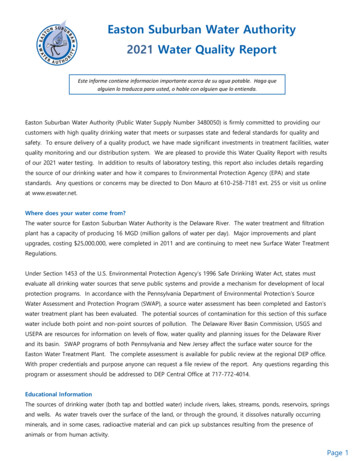
Ion Exchange-The Zone below the MTZ essentially clean zone and no adsorbed material on it.-With time the saturation zone depth increases and the MTZ is pushed downuntil we reach to a point where the clean zone disappears and breakthrough occurs.- Breakthrough is said to have occurred when the effluent concentration reaches to 5%of the influent concentration (i.e, Cb 0.05C0).-After additional time the MTZ start to decrease until it disappears and the bed iscalled exhausted. Exhaustion of the bed is assumed to have occurred when the effluentConcentration is equal to 95% of the influent concentration (i.e, C 0.95C0)-The length of the MTZ is calculated from the following equation (6.3): VE VBH MTZ Z .(7.2)V 0.5(V V)EB Ewhere H MTZ length of mass transfer zone, (m )Z height of the adsorption column, (m )VE throughput volume to exhaustion, m 3VB throughput volume to breakthrough, m 3-The area above the breakthrough curve is equal to the mass of the pollutantadsorbed in the column and equal to: X V0 (C0 C) dV .(6.4)22PDF created with pdfFactory Pro trial version www.pdffactory.com
Ion ExchangeMTZ δExhaustedC0MTZC 0.95C0 ExhaustionCleanCbCb 0.05C0VBVEFigure 7.723PDF created with pdfFactory Pro trial version www.pdffactory.com
Ion ExchangeExample 7.1 :below24PDF created with pdfFactory Pro trial version www.pdffactory.com
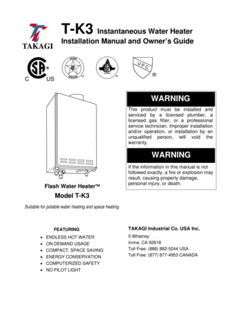
Ion ExchangeExample 7.1 Cont’d:Solution:-The data obtained from the labexperiment is summarized incolumns (1) and (2) in theTable to the right.-The data in columns1 and 2 are used to draw thebreakthrough curve as Shown infigure 7.8.-The data is arranged in columns4,5 and 6 in the forms necessaryto plot the Thomas equation asShown in figure 7.9.25PDF created with pdfFactory Pro trial version www.pdffactory.com
Ion ExchangeExample 7.1 Cont’d:- From Fig 7.9 the slopek1 Slope *k1C 0Q 0.7583 L-11.0428 L / d 1000 meqQ 0.7583L 1 234.6 L /( d eq )C03.37 meq / L1 eq- From Fig 7.9 the interceptq 0 intercept k1 q 0 MQ 15.33 L-1Q1000 g(1.0428 L/d ) 15.33 2.932 eq/kg resink 1M(234.6 L/d eq) 23.4 g1 kg-Mass of resin needed for the full scale column Can be found from the Thomasequation :k1q 0 Mk1C 0 V C0 1 ln QQ C 26PDF created with pdfFactory Pro trial version www.pdffactory.com
Example 7.1 Cont’d:Ion Exchange C0 1ln 1 ln 1 2.9444 0.05 0.05 C 0 k 1q 0 M234.6 L /(d eq )(2.932 eq / kg )( M kg ) Q378500 L / d234.6 L /(d eq)(3.37 meq / L) * (1 eq / 1000 meq) (7d 378500L)k 1C 0 V Q378500 L / dd-Substitute the three above terms in the Thomas equation and solve for M:M 4670 kg dry weight of resin- Resin volume (4670 kg)(1/0.56)(716.5 kg/m3) 11.6 m3Resin volume (π/4)(D2)(2D) 11.6 m3D 1.95 m (diameter of the column)Z 2D 3.9 m (depth of the resin bed)-Since it was assumed that the breakthrough occurs after 7 days ( at C 0.05C0) then thebreakthrough Volume (VB) 7*378500 2.65 X 10⁶ L-To find (VE) at C 0.95 C0 apply Thomas equation and solve for V, the result is:(VE) 5.47 X 10⁶ L- Since VB, VE, and Z are known find HMTZ apply equation 7.2, soHMTZ 2.69 m27PDF created with pdfFactory Pro trial version www.pdffactory.com
Ion ExchangeFigure 7.828PDF created with pdfFactory Pro trial version www.pdffactory.com
Ion ExchangeFigure 7.929PDF created with pdfFactory Pro trial version www.pdffactory.com
Ion Exchange7.1030PDF created with pdfFactory Pro trial version www.pdffactory.com
Ion ExchangeFigure 7.1031PDF created with pdfFactory Pro trial version www.pdffactory.com
Ion Exchangeresin on a dry weight basis. Determine the kilograms of resin required ifthe allowable breakthrough is seven days.32PDF created with pdfFactory Pro trial version www.pdffactory.com
The ion exchange system in water treatment: Ion Exchange a) Configuration of the ion exchanger (Figure 7.5):-The main component of the ion exchanger is a cylindrical steel tank with the following typical dimensions: Diameter 1-2 m Height 3-4 m (typical to the adsorption tanks) -The ion exchange bed occupies 1-3 meters of the tank height and .