Transcription
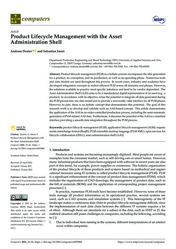
computersArticleProduct Lifecycle Management with the AssetAdministration ShellAndreas Deuter *and Sebastian ImortDepartment Production Engineering and Wood Technology, OWL University of Applied Sciences and Arts,Campusallee 12, 32657 Lemgo, Germany; sebastian.imort@th-owl.de* Correspondence: andreas.deuter@th-owl.de; Tel.: 49-5261-702-5305; Fax: 49-5261-702-85305Abstract: Product lifecycle management (PLM) as a holistic process encompasses the idea generationfor a product, its conception, and its production, as well as its operating phase. Numerous toolsand data models are used throughout this process. In recent years, industry and academia havedeveloped integration concepts to realize efficient PLM across all domains and phases. However,the solutions available in practice need specific interfaces and tend to be vendor dependent. TheAsset Administration Shell (AAS) aims to be a standardized digital representation of an asset (e.g., aproduct). In accordance with its objective, it has the potential to integrate all data generated duringthe PLM process into one data model and to provide a universally valid interface for all PLM phases.However, to date, there is no holistic concept that demonstrates this potential. The goal of thisresearch work is to develop and validate such an AAS-based concept. This article demonstratesthe application of the AAS in an order-controlled production process, including the semi-automaticgeneration of PLM-related AAS data. Furthermore, it discusses the potential of the AAS as a standardinterface providing a smooth data integration throughout the PLM process. Citation: Deuter, A.; Imort, S.Keywords: product lifecycle management (PLM); application lifecycle management (ALM); requirements interchange format (ReqIF); PLM extensible markup language (PLM XML); open services forlifecycle collaboration (OSLC); asset administration shell (AAS)Product Lifecycle Management withthe Asset Administration Shell.Computers 2021, 10, 84. https://doi.org/10.3390/computers10070084Academic Editor: Stefan BosseReceived: 23 April 2021Accepted: 16 June 2021Published: 23 June 2021Publisher’s Note: MDPI stays neutralwith regard to jurisdictional claims inpublished maps and institutional affiliations.Copyright: 2021 by the authors.Licensee MDPI, Basel, Switzerland.This article is an open access articledistributed under the terms andconditions of the Creative CommonsAttribution (CC BY) license (https://creativecommons.org/licenses/by/4.0/).1. IntroductionProducts and systems are becoming increasingly digitized. Most people are aware ofexamples from the consumer market, such as self-driving cars or smart homes. However,many industrial products that have been equipped with software in recent years are alsopart of this trend, for example, power supplies or connectors. The holistic organizationof the product lifecycle of these products and systems based on methodical and organizational measures using IT systems is called product lifecycle management (PLM). PLMis a significant enhancement of the concept of product data management (PDM), whichincludes the organization of CAD drawings; the management of product data, such asthe bill of materials (BOM); and the application of corresponding project managementprocesses [1].In practice, numerous PLM tools have become established. However, none of thesetools manage all product information or, in operational practice, several systems areused, such as CAD systems and simulation systems [2]. This heterogeneity of the ITlandscape makes a continuous data chain in product lifecycle management difficult, sincethe implementation of such data chain between the different IT systems requires a lotof effort. Although there are standards for a subset of the data, such as STEP or JT, theoutlined situation still poses challenges to companies, including the following, accordingto [3]:1.Due to individual item naming in the systems, different interpretations of an artefactoccur within companies.Computers 2021, 10, 84. ww.mdpi.com/journal/computers
Computers 2021, 10, 842 of 182.3.4.5.6.Different data formats are used for the same processes.Data should be accessible in such a way that it can also be used in areas for whichit was not intended when it was created. This also includes independence from thelocation as well as from the company.The completeness of data cannot be guaranteed because it is often stored in differentdata repositories or even exists as documents in digital or paper form.Data access is hindered by data security requirements.Effort is needed to make the data of one PLM system accessible to other systems.In addition to these points, the PLM processes of digitized products face anotherchallenge: traditional PLM systems are not designed to manage the creation of the softwareof digitized products and systems. Therefore, software engineers have developed socalled application lifecycle management (ALM) processes and tools in parallel to the PLMconcept. The goal of ALM is to provide a comprehensive technical solution for monitoring,controlling, and managing software development throughout the application lifecycle [4].Since digitized products and systems require PLM and ALM to work together, manyactivities and discussions in research and industry are currently actively targeting smoothPLM/ALM integration [5–7]. For example, the authors were members of a researchteam that developed use cases for PLM/ALM integration in an industrial case study [8].However, solutions such as those described above involve PLM/ALM solutions from onlyone vendor. Although the Open Services for Lifecycle Collaboration (OSLC) standard [9]was used in the case study, the solution remained vendor specific. However, the engineeringand production of digitized products require PLM/ALM integration between tools fromdifferent vendors. Today, to achieve this goal, custom interfaces are required (e.g., [10]).In addition, the emergence of the Digital Twin concept makes the smooth integrationof data and tools throughout the PLM phases, including the production process, even morenecessary. There are a variety of definitions of Digital Twin that differ in scope and level ofdetail [11]. However, the opinion that the data of the Digital Twin should be merged in anautomated way across all PLM phases is consolidating [12].To address these challenges, this work proposes an approach based on the AssetAdministration Shell (AAS). The result is a concept in which the data generated during theengineering and production of a digitized product or system is managed in the AAS. Thismakes the data available to all PLM phases in a standardized manner. A particular focus ofthis work is the integration of ALM data into the PLM process.This article is structured as follows: Section 2 explains the concept of the AAS andother relevant background information. Section 3 outlines the major research goals andthe research method. Section 4 describes the concept for using the AAS in the engineeringprocess. Section 5 extends the AAS-based data integration to the production process,reusing data of the engineering process. Section 6 discusses the achievement of the majorresearch goals and the success factors of the AAS-based strategy. The article concludeswith suggestions for further research topics and a final discussion.2. Related Background2.1. PLM and Systems EngineeringPLM is a comprehensive term, which generates numerous opinions. According to [1],it is “the business activity of managing, in the most effective way, a company’s products allthe way across their lifecycles; from the very first idea for a product all the way throughuntil it is retired and disposed of”. The overall objective is to increase revenue by reducingproduct-related costs and lead-times.PLM is related to the research field of systems engineering. There are many definitions of systems engineering. However, it is generally considered as an interdisciplinaryapproach that enables the successful implementation of systems [13]. It is obvious that theproduct lifecycle management of digitized products and systems also involves multipledisciplines or domains. A difference between these terms can be seen in terms of theimportance of IT tools: systems engineering is rather a set of methods that are independent
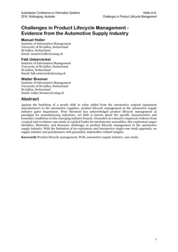
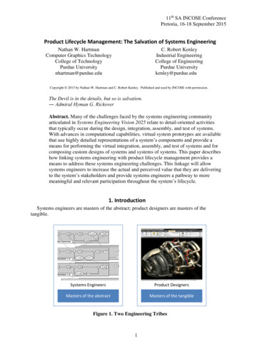
Computers 2021, 10, 843 of 18of concrete IT tools, while PLM includes a strong focus on IT tools. Nevertheless, anyactivity aiming for improved, standardized data integration throughout the PLM processcontributes to systems engineering research.2.2. Digital TwinThe Digital Twin is seen as a major tool for increasing the productivity in PLMprocesses in the age of industrial digitalization. Therefore, a number of publications arefocusing on this concept, creating several definitions of the term [11]. However, these arenot always of value in the practical implementation of Digital Twins in PLM processes.Although contradictory definitions do not hinder an investigation of the development ofDigital Twins in PLM processes, the authors presented an alternative approach to deal withDigital Twins. The so-called Digital Twin theory was proposed during the work on theTeDZ project (see section “funding”). Therefore, it is only briefly explained here. Despitethis focused view, the reader should be aware that a tremendous amount of research onDigital Twins has been conducted in recent years and continues to be carried out.Digital Twin theory assumes that throughout the PLM process there are multiple stakeholders with different perspectives on the digital representation of products and systemswho are working with this digital representation at the same time. These assumptions formthe basis of several hypotheses of a Digital Twin, namely [14]:1.2.3.4.5.6.7.8.A Digital Twin is a digital representation of an asset.A Digital Twin is located in several places simultaneously.A Digital Twin has multiple states.The Digital Twin has a context-specific state in a specific interaction situation.The information model for Digital Twins is infinitely large. It is called the realinformation model.The real information model can be finitely approximated for a specific applicationscenario, becoming a rational information model.The rational information model cannot be stored in a single place.The rational information model is never completely visible.For an explanation of these hypotheses, the reader is referred to the original article.4 of 18Figure 1 shows some of the elements named in the hypotheses and their relationto the PLM process.Computers 2021, 10, x FOR PEER tedAdaptedfromfromref.ref.[14].[14].2.3. Asset Administration Shell (AAS)The AAS data model consists of three main classes: the asset class, the submodelTwintheorya theoreticalconcept.doesprovidesnot indicateany guidelinesforclass,Digitaland theviewclass is(seeFigure 2). Theasset Itclassinformationon the kindcreatingA centraltechnologyimplementingDigitalTheTwinscan be seentheof asset Digital(type orTwins.instance)and theasset identificationsubmodel.submodelclassinrefersto a well-defined domain or subject matter (e.g., the asset identification and drive parameters). Submodels can be considered the main information store of an AAS, as they provide the central data on an asset. There is no limit to the number of submodel classes.When developing an AAS of an asset, any new submodel can be defined. This researchwork used submodel classes to model PLM data, such as the bill of materials (BOM).
Computers 2021, 10, 844 of 18Asset Administration Shell (AAS). However, there are many other technologies availableimplementing Digital Twins.The “Plattform Industrie 4.0”, a German consortium of politics, companies, andFigure 1. PLM infrastructurefor Digital Twins. Adapted from ref. [14].research organizations, introduced and specified the concept of the AAS [15]. In order topromote this concept, the Industrial Digital Twin Association (IDTA) was recently founded.The AAS dataof threeclasses:of theassetAnclass,submodelThe modelAAS is aconsistsstandardizeddigital mainrepresentationan asset.asset istheanythingof valueandclasscan bea physicalobject class(e.g., aprovidesproduct orinformationa service). Theclass, and the view(seeFigureor2).logicalThe ectsoftheassetintheformofsubmodelsanddescribesof asset (type or instance) and the asset identification submodel. The submodel class referstheasset’s technical functionality by displaying it via a standardized interface.to a well-defined domainor subjectmatter(e.g.,the mainassetclasses:identificationandthedriveparamThe AASdata modelconsistsof threethe asset class,submodelclass,eters). Submodelsandcanconsideredthe mainstoreinformationof an AAS,thebeviewclass (see Figure2). Theinformationasset class providesonasthetheykind proof asset(type orandTherethe ses.refers to avide the central dataoninstance)an asset.is nolimit to thenumbersubmodelwell-defineddomainor subject(e.g., the assetidentificationand Thisdrive researchparameters).When developingan AAS ofan asset,anymatternew submodelcanbe defined.Submodels can be considered the main information store of an AAS, as they provide thework used submodel classes to model PLM data, such as the bill of materials (BOM).central data on an asset. There is no limit to the number of submodel classes. WhenThe view classprovidesa projectionofanythenewAASmodelcanseena particularperdevelopingan AASof an asset,submodelbe fromdefined.This researchworkspective, omittingusedentitiesthatclassesare notrelevanttodata,thatsuchperspective.submodelto modelPLMas the bill of materials (BOM).Figure 2. Excerpt Figurefrom theAAS meta-model.Adapted fromref.from[15].ref. [15].2. Excerptfrom the AAS meta-model.AdaptedThe view class provides a projection of the AAS model seen from a particular perspec-In addition tive,to thesemain classes, the AAS data model defines many more classes,omitting entities that are not relevant to that perspective.providing detailed informationthe asset(e.g.,data datatypemodelclasses).Furthermore,theIn addition toaboutthese mainclasses,the AASdefinesmany more classes,AAS specificationprovidingdefinesdetailedthe representationof thedatadatamodelstandarddata in-theinformation aboutthe AASasset (e.g.,type inclasses).Furthermore,AASspecificationdefinesthe representationthe AASmodel inObjectstandarddataterchange formats,suchas interchange formats, such as Extensible Markup Language (XML) and JavaScript Objecttation (JSON).Notation (JSON).The AAS specification does not define how to implement an AAS. However, in orderto provide standardized implementations of the AAS from different vendors, severalinitiatives are currently active, including the AASX Package Explorer. This is an opensource software tool enabling a user to create, edit, and view an AAS [16]. Furthermore, itprovides access to the AAS via an Open Platform Communications Unified Architecture(OPC UA) or Message Queuing Telemetry Transport (MQTT) interface. This work usedthe AASX Package Explorer to demonstrate the submodels created for the purpose of the
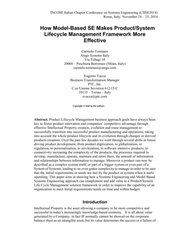
Computers 2021, 10, 845 of 18research. The second initiative to mention is the BaSys 4.0-Middleware, which provides anopen-source platform called BaSyx, supporting the implementation of a vendor-specificAAS [17,18].In order to provide PLM data in an AAS submodel structure, there must be thecorresponding data models. However, the “Plattform Industrie 4.0” has defined only a fewsuch AAS data models (e.g., digital nameplate). As none of these fit the purpose of thiswork, which focused on a general strategy to enable data integration throughout the PLMprocess with the AAS and not on the data models themselves, existing data models outsidethe AAS specification were used. They are explained in the next section.2.4. Selected Data Models in PLM ProcessesThere is no standardized all-encompassing PLM data model. However, there are phasespecific and domain-specific standards, respectively. For example, Siemens, a market leaderin the area of PLM software, defined the PLM XML schema [19]. It is a Siemens internaldata model of its PLM tool Teamcenter to exchange data between two Teamcenter instancesusing XML files. Furthermore, it supports application integration through workflows. PLMXML is a very comprehensive model. However, it is a proprietary format, and there is nowidespread acceptance in practice.Another example is derived from the ALM domain: there is no standardized datamodel for ALM. However, as requirements engineering is an important task in ALM, thereis a so-called Requirements Interchange Format (ReqIF) [20], enabling the exchange ofrequirements between different tools. Similarly to PLM XML, ReqIF enables data exchangebetween IT tools using XML. ReqIF originated in the automotive industry. However, sinceits standardization by the Object Management Group (OMG), it has also been applied inother industries and fields. ReqIF covers requirements as well as the documents containingthese requirements. Furthermore, as requirements are normally written in natural language,ReqIF is not limited to requirements but also supports other artefacts. For example, thiswork uses ReqIF to exchange assembly instruction data containing text and pictures.2.5. OSLC-Based Data IntegrationWhen discussing the exchange of data throughout a product lifecycle, one cannotneglect to mention the OSLC standard [9]. OSLC is designed to connect data and to createa digital thread across domains, applications, and organizations. It uses the concept knownas the Resource Description Framework (RDF) for data exchange between different applications. In order to enable OSLC-based data exchange, the tools involved must providean appropriate interface. In theory, data exchange between OSLC consumers and OSLCproviders is tool independent. However, in reality, tool integration can contain vendorspecific elements, meaning that only tools from a single vendor fit together optimally.Furthermore, the OSLC standard is not designed to facilitate anything other than dataaccess between tools. For example, operational data (e.g., device temperature) from anasset are not part of the OSLC design concept.Although there is no all-encompassing PLM data model, tool vendors offer proprietarysolutions for PLM data integration throughout the PLM process, as shown in the followingexample: As previously mentioned, the authors have already worked on concepts forPLM/ALM integration [6]. These activities made use of the Siemens toolchain withTeamcenter (PLM) and Polarion (ALM). Data exchange between these tools is based onthe OSLC standard (see Figure 3). In addition to various use cases from the industry, theresearch team created several other use cases for the so-called “SmartLight”, which is asimple mechatronic product involving the mechanical, electronic, and software domains(depicted in Figure 6). Among the use cases under investigation was the assignment of arequirement, managed in ALM, with a design element storing CAD data. Although theseCAD data are managed in Teamcenter, they can only be edited in the CAD tool Siemens NX.The data integration between NX and Teamcenter is based on an internal Siemens interface.
simple mechatronicproductinvolvingthe mechanical,electronic,and softwaredomains of a(depictedin Figure6). Amongthe use cases underinvestigationwas the assignment(depicted in Figurerequirement,6). Amongmanagedthe useincasesunderinvestigationwastheassignmentof atheseALM, with a design element storing CAD data. AlthoughCAD dataare managedTeamcenter,theystoringcan onlyCADbe editedin Althoughthe CAD toolSiemensrequirement, managedin ALM,with weenNXandTeamcenterisbasedonaninternalSiemensCAD data are managed in Teamcenter, they can only be edited in the CAD tool Siemensinterface.Computers 2021,84 data integration between NX and Teamcenter is based on an internal Siemens6 of 18NX.10,Theinterface.Figure 3. Teamcenter/Polarion interface (source: Siemens).Figure 4 shows an actual view of the Polarion user interface as an example of thePLM/ALM interface. The requirement “SLv2-69 Co Modulhousing Material” (ALM) islinked to the design elements “SL-Bottom piece” and “SL-Top component piece” (PLM).Figure3. Teamcenter/Polarioninterface(source:Siemens).To createsuch links,the Siemenstoolchainprovides specific dialogs. Furthermore,Figure 3. Teamcenter/Polarioninterface(source:Siemens).with the so-called “Delegated UI” technology, Teamcenter data can be edited in Polarion4 showsactualareviewof thespecificPolarionas anexampletheand Figurevice versa.Suchanvendoranduserare interfacenot coveredby theOSLCofspeciFigure 4 showsanactualviewfeaturesof requirementthe Polarionuser interfaceas an exampleof(ALM)the isPLM/ALMinterface.The“SLv2-69Co Modulhousing Material”fication. Therefore, the authors perceive an increasing need for vendor-independent apPLM/ALM interface.Therequirement“SLv2-69Co Modulhousing Material”(ALM)(PLM).islinkedto thedesign elements“SL-Bottom piece”and “SL-Top component piece”proachestolinkingsuch data.linked to the design elements “SL-Bottom piece” and “SL-Top component piece” (PLM).To create such links, the Siemens toolchain provides specific dialogs. Furthermore,with the so-called “Delegated UI” technology, Teamcenter data can be edited in Polarionand vice versa. Such features are vendor specific and are not covered by the OSLC specification. Therefore, the authors perceive an increasing need for vendor-independent approaches to linking such vendor-specificPLM/ALMPLM/ALM datadata linklink (screenshot(screenshot ofof SiemensSiemens Polarion).Polarion).Figure3. MajorResearchandSiemensResearchMethod provides specific dialogs. Furthermore,To createsuch Goalslinks, thetoolchainwith theUI” producttechnology,Teamcenterdata canbe senseeditedofinPolarThisso-calledresearch “Delegatedwork addresseslifecyclemanagementin ecificandarenotcoveredbytheOSLC4.0. As there are many aspects of Industry 4.0, the research team set itself the task of fospecification.theauthors definedperceiveinan[21],increasingcusing on theTherefore,applicationscenariosnamely:need for vendor-independentapproaches to linking such data. OCP—Order-Controlled Production; AF—AdaptableFactory;3. MajorResearch Goalsand Research Method SAL—Self-organizing Adaptive Logistics;Figure 4. Example of a vendor-specificPLM/ALMlink lifecycle(screenshotof SiemensPolarion).This research workaddressesdataproductmanagementin thesense of Industry VBS—Value-based Service;4.0. As there are many aspects of Industry 4.0, the research team set itself the task oftheResearchapplicationMethodscenarios defined in [21], namely:3. Major ResearchfocusingGoals onand OCP—Order-Controlled Production; TAP—Transparency and Adaptability of Delivered Products;This research workaddresses product lifecycle management in the sense of IndustryAF—Adaptable Factory;4.0. As there are manyaspects of Industry4.0, theresearch team set itself the task of fo SAL—Self-organizingAdaptiveLogistics; VBS—Value-basedService;in [21], namely:cusing on the applicationscenarios defined OCP—Order-Controlled Production; OSP—Operator Support in Production;AF—Adaptable Factory;SP2—Smart Product development for Smart istics; ce;Industrialexperts and renowned researchers have identified these application scenarios as enhancements of the current state of the art. Therefore, the intention of this work is
Computers 2021, 10, 84 TAP—Transparency and Adaptability of Delivered Products;OSP—Operator Support in Production;SP2—Smart Product development for Smart Production;IPD—Innovative Product Development.7 of 18Industrial experts and renowned researchers have identified these application scenarios as enhancements of the current state of the art. Therefore, the intention of this workis to create results that allow their implementation in practice. When discussing the projectto create results that allow their implementation in practice. When discussing the projectresults in Section 6, descriptions of these application scenarios are given.results in Section 6, descriptions of these application scenarios are given.This research work is divided into the creation of the conceptual basis to solve theThis research work is divided into the creation of the conceptual basis to solve theproblem, a practical implementation evaluation, and a theory building. It is based on theproblem, a practical implementation evaluation, and a theory building. It is based onmethodological approach of Design Research (DR). DR analyses the application of dethe methodological approach of Design Research (DR). DR analyses the application ofsigned IT artefacts to understand, explain, and improve information systems. As there aredesigned IT artefacts to understand, explain, and improve information systems. As thereseveral definitions of DR, this work follows the explanations in [22]. DR consists of twoare several definitions of DR, this work follows the explanations in [22]. DR consists of twoactivities: the design of one or more IT artefacts and theory building. The IT artefacts (inactivities: the design of one or more IT artefacts and theory building. The IT artefacts (inthiswork, these are the several AASs) and their contribution to an overall solution have athis work, these are the several AASs) and their contribution to an overall solution have alocallocal practicalpractical referencereference toto thethe SmartLight,SmartLight, whichwhich isis designeddesigned andand producedproduced inin aa inedinthedesignoftheITartefactsareand test factory. The local results obtained in the design of the IT artefacts are usedused toto pplicableresultsfromthem.Asthe theorizing with the aim of forming generally applicable results from them. As isalsoongoing.research work is ongoing, the theorizing process is also ongoing.TheThe designdesign ofof anan ITITartefactartefactconsistsconsists n.Thebuildingandevaluationphasescanberepeateding, and evaluation. The building and evaluation phases can be repeated severalseveral times,times,whichwhich waswas conductedconducted inin thisthis work.work. FigureFigure 55 showsshows thethe stepssteps ofof thethe methodologicalmethodological apapproachandtheirassignmenttotheDRphases.proach and their assignment to the DR phases.Figure 5.5. DesignDesign researchresearch approachapproach ofof thisthis work.work.Figure4. AAS-Based Engineering Process4. AAS-Based Engineering ProcessOne focus of this work lies in the engineering process, especially in the PLM/ALMOne focus of this work lies in the engineering process, especially in the PLM/ALMintegration. This section explains why and how the AAS is utilized in this context.integration. This section explains why and how the AAS is utilized in this context.4.1. Requirements4.1. RequirementsWhen aiming to create a vendor-independent standardized concept of PLM/ALMWhen aimingto create e requirementssuch a concept muststandardizedbe defined. Themajorofrequirementsintegration,foraresucha concept must be defined. The major requirementsidentified bythetherequirementsresearch teamas follows:identified by the research team are as follows: R1: The concept must be based on a standard in order to enable vendor-independentintegration. R2: The underlying data model must provide comprehensive access to all data createdfor or by an asset in order to include data other than PLM/ALM data.As well as these high-level requirements, the concept should fulfil specific requirements for PLM/ALM integration. However, these requirements are often user specific. Inorder to discuss the validity of the concept described in this article, several requirementsdeveloped in the industrial case study described in [8] were adopted as references. Given
Computers 2021, 10, 84integration.R2: The underlying data model must provide comprehensive access to all data created for or by an asset in order to include data other than PLM/ALM data.As well as these high-level requirements, the concept should fulfil specific require8 of 18ments for PLM/ALM integration. However, these requirements are often user specific.Inorder to discuss the validity of the concept described in this article, several requirementsdeveloped in the industrial case study described in [8] were adopted as references. hatmustbefulfilled:must be fulfilled: R3: ItIt mustworkitemwitha TeamcenteritemandandviceR3:must bebe possiblepossibletotolinklinka aPolarionPolarionworkitemwitha Teamcenteritemversa.vice ossiblepossibleaccessof anyattributeof a PolarionworkfromitemR5:to toaccessthethedatadataof anyattributeof a Polarionwork itemfromthe linkedTeamcenteritemandvice versa.thelinkedTeamcenteritem :iteminasingleaction.item in a single action.R7:WhenWhencreatingcreatinga
of the product lifecycle of these products and systems based on methodical and organi-zational measures using IT systems is called product lifecycle management (PLM). PLM is a significant enhancement of the concept of product data management (PDM), which includes the organization of CAD drawings; the management of product data, such as