Transcription
Topological Relationship Query Processing for ComplexRegions in Oracle SpatialYing Hu, Siva Ravada, Richard Anderson, Bhuvan BambaOracle Spatial TechnologiesOne Oracle DriveNashua, NH 03062, USA{ying.hu, siva.ravada, richard.anderson, bhuvan.bamba}@oracle.comABSTRACTAlthough geographic information systems (GIS) and spatialdatabase communities have extensively studied topologicalrelationships for more than two decades, there is little literaturedescribing how to efficiently implement them in GIS and spatialdatabase systems. This is rather surprising considering thattopological relationship queries are supported in many GIS andspatial database systems including IBM Informix Spatial andGeodetic DataBlades, ESRI SDE, Microsoft SQL server 2008,Oracle Spatial and PostGIS. In order to bridge this gap, we reportour experience with implementing several optimization techniquesin Oracle Spatial to speed up topological relationship queryprocessing for query windows represented by complex regions(such as polygons or multi-polygons). Our experiments, utilizingreal-world data sets, demonstrate that topological relationshipquery performance can be significantly improved using theproposed techniques.Categories and Subject DescriptorsH.2.8 [Database Management]: Database Applications – spatialdatabases and GIS.General TermsAlgorithms, Management, Performance, Design, Experimentation.KeywordsTopological relationships, 9-intersection model, in-memory Rtree, spatial query processing.1. INTRODUCTIONTopological relationships have been studied by GIS and spatialdatabase communities for more than two decades. Seminal worksinclude the 9-intersection model [6, 8, 24] and the RegionConnection Calculus (RCC) model [7]. These models can be usedto define different topological relations such as touch, overlap,inside, and contains. However, as described in [24], literature onthe actual implementation of these topological relationships,especially in the context of commercial GIS and spatial databasesystems, is rare. This is very surprising as many spatial databasePermission to make digital or hard copies of all or part of this work forpersonal or classroom use is granted without fee provided that copies arenot made or distributed for profit or commercial advantage and thatcopies bear this notice and the full citation on the first page. To copyotherwise, or republish, to post on servers or to redistribute to lists,requires prior specific permission and/or a fee.ACM SIGSPATIAL GIS '12, November 6–9, 2012. Redondo Beach, CA,USACopyright 2012 ACM ISBN 978-1-4503-1691-0/12/11 15.00and GIS vendors [9, 12, 17, 20, 23] already support topologicalrelationship queries. In order to resolve this discrepancy, wepresent in this paper our experience with implementing severaloptimization techniques in Oracle Spatial to speed up topologicalrelationship query processing when complex regions are used asquery windows.Topological relationship queries with complex regions are veryimportant. For example, an insurance company may need tosearch for properties within a flooded region. This is often calleda point-in-polygon query [16]. Other examples include searchingfor land parcels touching a lake, highways crossing a city, andnumerous similar spatial queries. These complex regions (like aflood zone, a lake or a city) are represented as polygons or multipolygons. In the rest of this paper, we simply use the term “querypolygon” for both the polygon and multi-polygon geometries thatare used to run queries against test geometries. The performanceof these topological relationship queries is one of the mostimportant aspects of GIS and spatial database systems. Todemonstrate the effectiveness of our optimization techniques forthese topological relationship queries, we utilize real-world datasets to conduct an experimental study.The rest of this paper is organized as follows: Section 2 reviewsrelated work. Section 3 discusses some preliminary conceptsincluding geometry validation and topological relationships inOracle Spatial. Section 4 reviews the in-memory R-treetechniques. Sections 5 and 6 describe some optimizationtechniques used for minimal bounding rectangles (MBRs) and fordifferent test geometries, respectively. Some extensions such asOpen Geospatial Consortium (OGC) Model [19] are discussed inSection 7. Section 8 presents results of an experimental studyusing real-world data sets. Section 9 concludes the paper.2. RELATED WORKSweep line-based line intersection algorithms are well known: avertical line moves from left to right, intersecting the linesegments in sequence [2, 21]. Several implementations oftopological relationship query processing are based on the sweepline technique [5, 13]. However, in enterprise GIS and spatialdatabase systems two factors can cause performance problems forthese sweep line-based algorithms: (1) the number of testgeometries; and (2) the complexity of test geometries and querygeometries.To address the problem of a large number of geometries, spatialindexes can be built to reduce the search scope. This is the twostep query processing method: (1) the filter step utilizes spatialindexes and returns a candidate set; (2) the refinement step is atest on exact geometries in the candidate set [3]. In commercialdatabase systems two classes of spatial indexes, — Quad-treeindexes and R-tree indexes, are typically supported. For example,
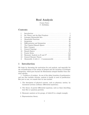
BMicrosoft SQL server supports multiple-level Quad-tree indexes[10, 17] and Oracle Spatial supports both Quad-tree and R-treeindexes [15]. Since Quad-tree indexes typically need more finetuning to set an appropriate tessellation level, and they can onlybe used to index 2-dimensional (2D) non-geodetic geometries inOracle Spatial, this paper will focus on the use of R-tree indexes.For R-tree indexes, topological relationship with MBRs has beenwell studied [22].Previous works, which address the second problem of geometrycomplexity, include interior approximations [1, 14] and TR*-tree[4]. The interior approximations work [14] discusses tessellationof non-geodetic query polygons. If a point or an MBR is inside aninterior tile, then this point or MBR is also inside the querypolygon. The TR*-tree [4] is a representation of polygonalobjects; a polygon is decomposed into trapezoids and an R*-treeis built on top of these trapezoids to speed up the INTERSECTSoperation. For geodetic geometries, Voronoi tessellations can alsobe used to speed up geodetic computations [12]. Recently, [11]discussed how an in-memory R-tree, built on top of boundary linesegments of a polygon, can be used to speed up both geodetic andnon-geodetic point-in-polygon queries. In PostGIS [23] and JTS[13], a similar concept of “prepared geometry” can be used for theINTERSECTS and CONTAINS operations. An in-memoryinterval tree can be used for point-in-polygon computations andan in-memory R-tree can be used for line-line intersections.This paper extends the techniques presented in our previous work[11] to different types of test geometries, such as multi-point, line,multi-line, polygon and multi-polygon, and discusses theprocessing of different topological relationship queries for querypolygons in Oracle Spatial. In addition, these techniques havebeen extended to other query geometries like query points, querylines, and collections of query points, query lines and querypolygons in Oracle Spatial. However, we will focus primarily onquery polygons in this paper, due to their extensive usage withrespect to other query geometry types.3. KEY CONCEPTSIn this section, we review some basic concepts that are used in therest of this paper.3.1 Two-dimensional Geometry ValidationA point is a 0-dimensional geometry, and its boundary is NULL.A multi-point is also a 0-dimensional geometry and its boundaryis also NULL.Both a line and a multi-line are a 1-dimensional geometry andthey can be self-crossing. In Oracle Spatial, the boundary of a lineor multi-line is determined by checking if the end points touchany point of this line or multi-line. Note that this is different fromthe OGC’s “mod 2” union rule [19]: a point is in the boundary ofa line or multi-line if it is in the boundaries of an odd number ofelements of the line or multi-line. For example, in Figure 1, case(1) displays a single line; point B is in the boundary while point Ais not in the boundary according to Oracle Spatial’s rules. Case(2) displays a multi-line composed of two lines EF and CD, whereline CD is closed and point E is the same as points C and D.According to OGC’s “mod 2” union rule, point E, C, or D is inthe boundary. But in Oracle Spatial, point E, C, or D is notincluded in the boundary. Note that both case (1) and case (2) areequivalent from the perspective of topological relationships, andin both cases, points A, and C, D or E respectively are consideredas interior points in Oracle Spatial.FEAC(1)D(2)Figure 1. Determination of boundary of a line or a multi-linein Oracle Spatial.Both a polygon and a multi-polygon are a 2-dimensionalgeometry. Restrictions imposed on both polygon and multipolygon geometries include: They must not be self-crossing. They must be oriented correctly. That is, exterior ringboundaries must be oriented counter-clockwise and interiorring boundaries must be oriented clockwise. The interior of each polygon is connected.These restrictions allow us to determine if a point or a line residesinside or outside a query polygon locally.3.2 Topological RelationshipsAlthough Oracle Spatial supports the OGC topologicalrelationships including EQUALS, DISJOINT, INTERSECTS,TOUCHES, CROSSES, WITHIN, CONTAINS and OVERLAPS[19], we would prefer to use the original 9-intersection model in[6] because it separates the WITHIN operation into two: INSIDEand COVEREDBY; this makes it easier to explain theimplementation details. Therefore, we will focus on the original 9intersection model and postpone the discussion of OGC’stopological relationships to Section 7.4.The 9-intersection model can be described as a matrix, as shownin Figure 2. We use the following notion to indicate which bit isset. When boundary (b), interior (i), exterior (e) of test geometryB intersects boundary (b), interior (i), exterior (e) of querygeometry A, bit [b i e] [b i e] (the first [b i e] is for test geometryB and the second [b i e] is for query geometry A) is set. Forexample, bit b b, bit b e, bit i e, bit e b, bit e i and bit e eare set in Figure 2.Figure 2: 9-intersection matrix.In Oracle Spatial, two enhancements are added on the original 9intersection model: 1) OVERLAPBDYDISJOINT andOVERLAPBDYINTERSECT are treated separately. Thisseparation is useful to distinguish some cases as shown in Figure3 and Figure 4. 2) ON is added for cases where a point, multipoint, line, or multi-line is completely on the boundary of apolygon. In this scenario, ON is a special case of TOUCH. TheON relationship is added because many Oracle Spatial users
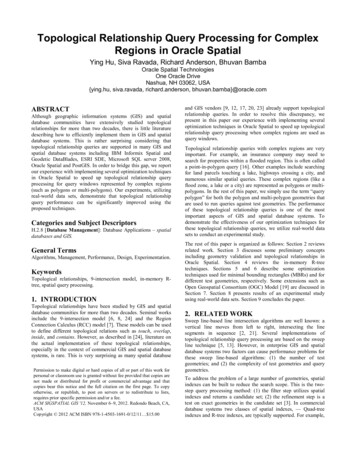
would like to distinguish it from the TOUCH relationship. Forexample, some users may use “INSIDE COVEREDBY ON”(a composite topological relationship that will be discussed inSection 7.3) to retrieve all roads completely in the boundary andinterior of a city. In addition, we also support the converserelationship of ON internally, which is also a special case ofTOUCH.COVERS: The interior of one object is completely contained inthe interior or the boundary of the other object and theirboundaries intersect. If any of bit e b and bit e i is set, it is notCOVERS.INSIDE: The opposite of CONTAINS. A INSIDE B implies BCONTAINS A. If any of bit b b, bit b e, bit i b and bit i e isset, it is not INSIDE.COVEREDBY: The opposite of COVERS. A COVEREDBY Bimplies B COVERS A. If any of bit b e and bit i e is set, it isnot COVEREDBY.ON: The interior and boundary of one object is on the boundaryof the other object. This is a special case of TOUCH. If any ofbit b i, bit b e, bit i i and bit i e is set, it is not ON.ANYINTERACT: The objects are non-disjoint. This is the sameas INTERSECTS in the OGC model. If any of bit b b, bit b i,bit i b and bit i i is set, it is ANYINTERACT.Note that bit e e is always set for all of the above topologicalrelationships because we assume that no geometry can span thewhole universal space.4. IN-MEMORY R-TREE ON QUERYPOLYGONFigure 3. Topological relationships in Oracle Spatial.ABAFigure 4. Another OVERLAPBDYDISJOINT case: querygeometry A is a multi-polygon and test geometry B is apolygon.The definition of topological relationships in Oracle Spatial andusage of the 9-intersection bits to identify or rule out existingtopological relationships are as follows:DISJOINT: The boundaries and interiors do not intersect. This isthe same as DISJOINT in the OGC model. If any of bit b b,bit b i, bit i b and bit i i is set, it is not DISJOINT.TOUCH: The boundaries intersect but the interiors do notintersect. This is the same as TOUCHES in the OGC model. Ifbit i i is set, it is not TOUCH.OVERLAPBDYDISJOINT: The interior of one object intersectsthe boundary and interior of the other object, but the twoboundaries do not intersect. If bit b b is set, it is notOVERLAPBDYDISJOINT.OVERLAPBDYINTERSECT: The boundaries and interiors ofthe two objects intersect. If all bit b b, bit i i, bit i e and bit e iare set, it is OVERLAPBDYINTERSECT.EQUAL: The two objects have the same boundary and interior.This is the same as EQUALS in the OGC model. If any of bit b i,bit b e, bit i b, bit i e, bit e b and bit e i is set, it is notEQUAL.CONTAINS: The interior and boundary of one object iscompletely contained in the interior of the other object. If any ofbit b b , bit b i , bit e b and bit e i is set, it is not CONTAINS.In [11], we described an in-memory R-tree built on top ofboundary line segments of a query polygon. Unlike a TR*-treethat is built on top of trapezoids [4], we utilize an in-memory Rtree, built on top of boundary line segments of a query polygon,because we can easily extend this technique to geodetic polygons,internally represented as geocentric 3D surfaces in Oracle Spatial.Furthermore, we have extended this technique to include otherquery geometries like query points, query lines, and collections ofquery points, query lines, and query polygons. Therefore, in an inmemory R-tree, leaf entries can be made up of points or linesegments (either boundary line segments of a query polygon, orjust line segments of a query line). However, we will focusprimarily on query polygons in this paper.To simplify our discussion, we use non-geodetic query polygonexamples in this paper, except in Section 7.1 where geodeticquery polygons are briefly discussed, and Section 8. Figure 5shows a query polygon comprising 14 line segments (shown inblue). Each line segment is used to obtain its respective MBR,which corresponds to an entry in a leaf node. An in-memory Rtree can be built on the 14 MBRs in Figure 5, marked with dashedlines; and four MBRs marked with dotted lines represent the leafnodes of the in-memory R-tree. Note that some lines in theseMBRs are both dashed and dotted. The root MBR is not shown inorder to make the four MBRs for the leaf nodes more distinct.Note that because the in-memory R-tree is built once per querypolygon, the cost of building it is amortized over a large numberof test geometries.Figure 5 also shows a green MBR (M), from a disk-based R-treeindex, inside the query polygon. It is obvious that M’sdescendants will also be inside the query polygon.To decide if an MBR is inside a query polygon, we use a two-stepprocedure:(1) Search the in-memory R-tree to determine if there is anyintersection between the MBR and line segments of thequery polygon. Note that, although the MBR (M) intersectswith the entry MBR (N) in Figure 5, it does not intersect
with any line segments in the query polygon. If there is anyintersection, child MBRs of the MBR (M) will be fetchedfrom disk or buffer cache for further processing recursively.Otherwise, go to the next step.(2) Choose the right-top corner point of the MBR (M) and drawa horizontal line segment L (shown in red) from this point tocross the maximum X value of the query polygon. Then theline segment L can be used to search the in-memory R-treeagain and get how many line segments of the query polygonintersect with it. If the number of intersections is odd it isguaranteed that the corner point is inside the query polygon,and thus the whole MBR and its descendants are alsocompletely inside the query polygon. Otherwise, the MBRand its descendants can be skipped.Note that in step (2), we can also use the R-tree Nearest Neighbor(NN) search method to identify the point on the query polygonthat is the closest to the right-top corner point of the MBR (M)and determine if the right-top corner point of the MBR (M) isinside the query polygon. More details can be found in [11]. Theabove two steps are also applied to a point: the first step dealswith the case of point-on-polygon, while the second step dealswith the case of point-in-polygon.L5.1 Non-Leaf MBR OptimizationsThe in-memory R-tree for the query polygon allows us to quicklydetermine if a non-leaf MBR is inside, intersects or is outside thequery polygon. The following optimizations can be used to furtherdetermine the topological relationships. For ANYINTERACT and INSIDE, if a non-leaf MBR isinside the query polygon, its descendant test geometries canbe returned without further checking. For all topological relationships except DISJOINT, if a nonleaf MBR is outside the query polygon, its descendant testgeometries can be discarded. For COVEREDBY, ON, OVERLAPBDYDISJOINT,OVERLAPBDYINTERSECT and TOUCH, if a non-leafMBR does not intersect the query polygon ring, itsdescendant test geometries can be discarded.5.2 Leaf MBR OptimizationsFor a leaf MBR, we can quickly determine if it is inside,intersects, or is outside the query polygon. We can then use thefollowing optimizations similar to those previously presented inSection 5.1. For ANYINTERACT and INSIDE, if a leaf MBR is insidethe query polygon, its test geometry can be returned withoutfurther checking. For all topological relationships except DISJOINT, if a leafMBR is outside the query polygon, its test geometry can bediscarded. For COVEREDBY, ON, OVERLAPBDYDISJOINT,OVERLAPBDYINTERSECT and TOUCH, if a leaf MBRdoes not intersect the query polygon ring, its test geometrycan be discarded.YMNXFigure 5. An in-memory R-tree is built on a query polygon.When a leaf MBR intersects a query polygon, we will performadditional optimizations for ANYINTERACT, COVEREDBY,INSIDE, ON and TOUCH by checking if each of the fourboundary edges of the leaf MBR is inside or outside the querypolygon:In practice, however, we limit the memory usage associated withthe in-memory R-tree structure by grouping several line segmentsinto a single entry to construct the in-memory R-tree structure.For example, assume that a query polygon has 50,000 linesegments. If we can group 10 continuous line segments into oneentry, there will be only 5,000 entries instead of 50,000 entriesoriginally. For COVEREDBY, INSIDE and ON, if any of the fourboundary edges is outside the query polygon, its testgeometry can be discarded. For ON and TOUCH, if any of the four boundary edges isinside the query polygon, its test geometry can be discarded. For ANYINTERACT, if any of the four boundary edges isinside the query polygon, its test geometry can be returned.5. MBR OPTIMIZATIONSFigure 6 explains the above three optimizations: 1) The testgeometry enclosed by leaf MBR (M’) cannot be COVERED,INSIDE or ON the query polygon because the right boundaryedge is totally outside the query polygon. 2) The test geometryenclosed by leaf MBR (M’) cannot TOUCH the query polygonbecause the left boundary edge is totally inside the query polygon.3) For ANYINTERACT, we can return the test geometry enclosedby leaf MBR (M’) without further computation because the leftboundary edge is totally inside the query polygon and the testgeometry must intersect the query polygon. Furthermore, inFigure 6, if the test geometry enclosed by leaf MBR (M’) is asingle polygon, OVERLAPBDYINTERSECT will hold true. Ifthe test geometry is not a single polygon, then eitherOVERLAPBDYINTERSECT or OVERLAPBDYDISJOINT willhold true.In the filter step of the two-step query processing [3], topologicalrelationships with MBRs have been well studied for R-trees [22].This section will focus on some new optimization techniquesadded on top of the previous work [22]. These new techniques arebased on the in-memory R-tree on query polygon and they applyto all topological relationships except CONTAINS, COVERS,and EQUAL. For example, if the MBR of a test geometry alreadycontains the MBR of a query polygon, the MBR of the testgeometry will also contain the entire query polygon. Thus,CONTAINS, COVERS, and EQUAL do not require these newMBR optimizations.
Note that 1) as a point or multi-point geometry have no boundary,bit b i, bit b b and bit b e are not set; 2) as the exterior of apoint or multi-point geometry intersects boundary, interior andexterior of a query polygon, bit e i, bit e b and bit e e can beset for all cases. So the only difference among the different casesis how we set bit i i, bit i b and bit i e. In other words, settingbit i i, bit i b and bit i e allows us to determine the topologicalrelationship. For instance,Leftboundaryedge isinsidethe querypolygonM’Rightboundaryedge isoutsidethe querypolygonFigure 6. A boundary edge of a leaf MBR can be inside oroutside a query polygon.6. TEST GEOMETRY OPTIMIZATIONSThe filter step, including the MBR optimizations in Section 5,discards some test geometries while some are returned withoutfurther computation. The remaining test geometries are candidatesfor further processing. In this section, we will discuss a method todetermine the topological relationship between a candidate testgeometry and a query polygon.In Section 3.2 we discussed the 9-intersection bits used to identifyor rule out different topological relationships. For example, whenbit i i is set, we can immediately rule out the TOUCHrelationship. In this section, we discuss the method fordetermining the 9-intersection bits. Note that we assume that testgeometries are valid, and we do not sort the coordinates in testgeometries. In other words, we use the original sequence of pointsin a test geometry to set the 9-intersection bits sequentially,locally and independently, and we do not need to carry much stateinformation. This is different from sweep line-based algorithmswhere coordinates in both query geometries and test geometrieshave to be sorted and an event queue has to be maintained.Furthermore, it is possible that some coordinates or points in atest geometry are not accessed at all. For example, for a TOUCHoperation, when a point or a line segment from a test geometry isalready determined to be inside a query polygon, or bit i i is set,we can stop processing the rest of coordinates or points in this testgeometry and discard it.We will split this section into three subsections based on the testgeometry types and explain different optimization techniques.6.1 Test Point Geometry OptimizationsWhen the test geometry is a single point, there are only threetopological relationships to a query polygon: INSIDE, ON (aspecial case of TOUCH) and DISJOINT, which correspond tobit i i, bit i b and bit i e being set, respectively. As these can bedone by the techniques previously discussed in Section 4, we willskip them.For a multi-point test geometry, we use the same techniquesdescribed in Section 4 to determine if each point is inside, on oroutside a query polygon (bit i i, bit i b and bit i e is setcorrespondingly). If only bit i i is set, the topological relationship is INSIDE. If only bit i b is set, the topological relationship is ON.Note that ON is a special case of TOUCH. So for a TOUCHquery, a test geometry, whose topological relationship is ON,is also returned. If only bit i e is set, the topological relationship isDISJOINT. If only bit i b and bit i i are set, the topologicalrelationship is COVEREDBY. If only bit i b and bit i e are set, the topologicalrelationship is TOUCH. If bit i i and bit i e are set, the topological relationship isOVERLAPBDYDISJOINT, regardless of bit i b being setor not. If any of bit i b and bit i i is set, the topologicalrelationship is ANYINTERACT.6.2 Test Line Geometry OptimizationsFor a query polygon, when the test geometry is a line or multiline, the topological relationships CONTAIN, COVERS, andEQUAL cannot hold true, but all other topological relationshipsare possible. First, we determine which end points are in theboundary as described in Section 3.1. If some end points are inthe boundary, we check if they are inside, on or outside the querypolygon, which corresponds to setting bit b i, bit b b andbit b e respectively. In addition, we can make the followinginferences: 1) when bit b i is set, bit i i can also be set; 2) whenbit b b is set, bit e b can also be set; 3) when bit b e is set,bit i e can also be set. For the remaining end points that are notin the boundary, we also check if they are inside, on or outside thequery polygon, which corresponds to setting bit i i, bit i b andbit i e. This can be accomplished in a manner similar to thediscussion in Section 4 because the end points are still points.We can now focus on the manner in which the other portion ofline or multi-line (i.e. except its end points) intersects the querypolygon, which also corresponds to how the bits bit i i, bit i band bit i e are set. As a line or multi-line can contain many linesegments, we describe how the three bits are set for each of theline segments. Figure 7 shows such a line segment SE. Thisfunction is performed in two major steps:(1) Use the line segment SE to search the in-memory R-tree todetermine whether or not there is any intersection orcollinearity between the line segment SE and boundary linesegments of the query polygon. For example, in Figure 7,there are 3 intersection points A, B and C, and line segmentAB is collinear with the boundary of the query polygon. Wecan view the line segment SE as being split into four newlygenerated line segments: SA, AB, BC and CE. Hence, bit i bcan be set if there is any intersection or collinearity.
(2) For each newly generated line segment that is not collinear,namely SA, BC and CE in Figure 7, we use an intersectionpoint to search the in-memory R-tree to determine if thisnewly generated line segment is either inside or outside thequery polygon. For example, for line segment BC, either B orC can be used, as both are intersection points. The questionarises as to why use an intersection point to search the inmemory R-tree. This is done because a line segment canintersect the boundary of a polygon or multi-polygon at thesame intersection point many times and we need to scan allintersecting boundary edges and return the closest one. Forexample, in Figure 8, the query region is a multi-polygon withthree exterior rings and one interior ring meeting at point D.Line segment S’E’ also intersects the multi-polygon at pointD. After scanning all intersecting boundary edges andmeasuring the angle of intersection, we determine that linesegment DX is the closest to line segment S’D and linesegment YD is the closest to line segment DE’. Note that, inOracle Spatial, polygons are oriented: Exterior ringboundaries must be oriented counterclockwise and interiorring boundaries must be oriented clockwise. Therefore, we caneasily determine that newly generated line segment S’D isinside and DE’ is outside the query polygon, whichcorresponds to setting bit i i and bit i e.When the test geometry is a line or multi-line and query geometryis a polygon or multi-polygon, setting bit b b, bit b i, bit b e,bit i b, bit i i and bit i e is sufficient and the topologicalrelationship can be determined in a similar fashion as for pointdata geometry. For example, if only bit b i and bit i i, or onlybit i i of the above six bits are set, topological relationshipINSIDE holds true. So we don’t need bit e b, bit e i andbit e e, although bit e i and bit e e can always be set.SABCEFigure 7. Line segment intersecting a query polygon.6.3 Test Polygon Geometry OptimizationsFor a query polygon, when the test geometry is either a polygonor multi-polygon, all topological relationships except ON arepossible, as shown in Figures 3 and 4. Similar to the procedure fora test line geometry, we take the first point in each polygon ring ofa test polygon geometry and determine if this point is inside, on oroutside the query polygon, which corresponds to setting bit b i,bit b b or bit b e respectively. In addition, we can make thefollowing inferences: 1) when bit b i is set, bit i i and bit e ican also set; 2) when bit b e is set, bit i e can also be set. Inother words, if a boundary point of a test polygon is inside a querypolygon, there must be an exterior point of the test polygon andan interior point of the test polygon inside the query polygon; if aboundary point of a test polygon is outside a query polygon, theremust be an interior point of the test polygon outside the querypolygon. This step is necessary because it is possible that polygonrings in both a test polygon and a query polygon do not intersecteach other.XS’DYE’Figure 8. A line segment intersects a query polygon at thesame point more than once.We can now focus on the case where polygon rings in both a testpolygon and a query polygon intersect each other. This is alsosimilar to what we have done for test line geometries. Assume thatline segment SE in Figure 7 is from a test polygon, and its interioris on its left side while its exterior is on its right side, as exteriorring boundaries must be oriented counterclockwise and interiorring boundaries must be oriented clockwise. The 9-intersection bitdetermination is also performed in two major steps:(1) Use the line segment SE to search the in-memory R-tre
step query processing method: (1) the filter step utilizes spatial indexes and returns a candidate set; (2) the refinement step is a test on exact geometries in the candidate set [3]. In commercial database systems two classes of spatial indexes, — Quad-tree indexes and R-tree indexes, are typically supported. For example,