Transcription
User ManualNMEA 2000 Wi-Fi Gateway YDWG-02also covers modelsYDWG-02R, YDWG-02NFirmware version1.172018
Package ContentsDeviceThis ManualPaperclip for resetNMEA 2000 Drop Cable1 pc.1 pc.1 pc.not suppliedNote: Device can be connected to the network backbone directly, withoutan NMEA 2000 drop cable. 2018 Yacht Devices Ltd. Document YDWG02-007, September 25, 2018.Web: http://www.yachtd.com/NMEA 2000 is a registered trademark of the National Marine ElectronicsAssociation. SeaTalk NG is a registered trademark of Raymarine UK Limited.Garmin is a registered trademark of Garmin Ltd.
ContentsIntroductionWarranty and Technical SupportI. Product SpecificationII. Installation of Device and Connection to NMEA 2000 NetworkIII. Wi-Fi SettingsIV. Configuration of Application ProtocolsV. NMEA 0183 and NMEA 2000 Message FiltersVI. LED SignalsVII. Reset of Settings and Hardware ResetVIII. Recording of Diagnostics DataIX. Firmware UpdatesX. NMEA Settings and Autopilot ControlXI. Web Gauges of Administrative Web SiteAPPENDIX A. TroubleshootingAPPENDIX B. Device ConnectorsAPPENDIX С. NMEA 2000 Messages Supported by DeviceAPPENDIX D. Conversions Between NMEA 2000 and NMEA 0183APPENDIX E. Format of Messages in RAW Mode46791115192325262830353739404150
IntroductionThe NMEA 2000 Wi-Fi Gateway (hereinafter Gateway or Device) allows youto see data from an NMEA 2000 marine digital network on a PC or smartphone. Withit, you get marine network data including vessel course, speed, position, wind speedand direction, water depth, AIS messages from vessels and aircrafts and othernavigation data in popular software applications.The Web Gauges page of administrative web site allow real time viewing of vessel datausing a web browser on PC, laptop, tablet or smartphone and can replace instrumentdisplays. No internet connection or app installation is required.The Device creates its own Wi-Fi network (with range of about 30 metersin open spaces) or it can be connected to an existing Wi-Fi network. In the secondcase, coverage depends on the coverage of the base network; laptops and PCscan be connected to Wi-Fi routers (and the Gateway services) by Ethernet; and you canconfigure remote access to the Gateway over the Internet.To configure the Gateway, you need any Wi-Fi enabled device (laptop or smartphone)with any web browser. The Device’s settings can be reset to factory values usingthe hidden reset button (a paper clip is required, supplied with the Device).The Gateway supports TCP and UDP network protocols (both can be enabledat the same time). For UDP protocol, the number of clients (physical devicesor software applications) is unlimited.A pair of Wi-Fi Gateways can act as an NMEA 2000 wireless extender and allowsjoining of two or more physical networks. To pair the gateways, you need to set up bothusing UDP protocol and set the same port number.—4—
The Device has a bi-directional converter between NMEA 2000 and NMEA 0183protocols. NMEA 0183 protocol has been widely supported in marine applicationssince the last millennium. So the Device is compatible with virtually all marinesoftware, except applications especially designed for use only with specific hardware.A powerful system of data filters allows configuring data output for feature-limitedmobile applications.The Gateway also supports RAW protocol, which is supported in a popularExpedition 10 and CAN Log Viewer. It allows transferring of any NMEA 2000messages (including proprietary messages) to an application and in the reversedirection. This protocol is open and is also supported by our USB Gateway. We hopethat it will be popular among software developers, because it is very simple and free.We hope that you’ll like this tiny and low power Device. Thank you for purchasingour product and happy voyages!—5—
Warranty and Technical Support1.The Device warranty is valid for two years from the date of purchase. If a Devicewas purchased in a retail store, the sales receipt may be requested when applyingfor a warranty claim.2.The Device warranty is terminated in case of violation of the instructionsin this Manual, case integrity breach, or repair or modification of the Devicewithout the manufacturer’s written permission.3.If a warranty request is accepted, the defective Device must be sent to themanufacturer.4.The warranty liabilities include repair and/or replacement of the goodsand do not include the cost of equipment installation and configuration, or shippingof the defective Device to the manufacturer.5.Responsibility of the manufacturer in case of any damage as a consequenceof the Device’s operation or installation is limited to the Device cost.6.The manufacturer is not responsible for any errors and inaccuracies in guidesand instructions of other companies.7.The Device requires no maintenance. The Device’s case is non-dismountable.8.In the event of a failure, please refer to Appendix A before contacting technicalsupport.9.The manufacturer accepts applications under warranty and provides technicalsupport only via e-mail or from authorized dealers.10.The contact details of the manufacturer and a list of the authorized dealersare published on the website: http://www.yachtd.com/.—6—
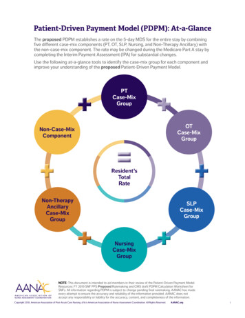
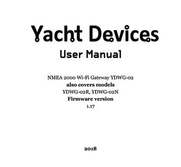
I. Product SpecificationFigure 1. Drawing of YDWG-02N and YDWG-02R models of GatewayOur devices are supplied with different types of NMEA 2000 connectors. Modelscontaining R in the suffix of model name are equipped with NMEA 2000 connectorsand are compatible with Raymarine SeaTalk NG. Models containing N in the suffixare equipped with NMEA 2000 Micro Male connectors. See connector drawingsin Appendix B.—7—
Device parameterValueSupply voltage (from NMEA 2000 network)Unit7.17VCurrent consumption43mAProtection against reverse polarityYes—1LENLoad equivalency numberWi-Fi module 2.4 GHz802.11b/g/n—30 / 100m / feetWi-Fi connections in Access Point mode (max.)3—TCP connections from applications (max.)9—Wi-Fi internal antenna range (open space)UDP clients (applications or devices)Device case lengthWeightOperating temperature rangeUnlimited—54mm18gr-20.55 СThe Wi-Fi antenna is located inside under the LED.Yacht Devices Ltd declares that this product is compliant with the essentialrequirements of EMC directive 2014/30/EU and radio and TTE directive1999/5/EC.Dispose of this product in accordance with the WEEE Directive. Do not mixelectronic disposal with domestic or industrial refuse.—8—
II. Installation of Device and Connection to NMEA 2000 NetworkThe Device requires no maintenance. When deciding where to install the Device,choose a dry mounting location. Avoid places where the Device could be floodedwith water, as this can damage it.Note that conductive materials (metals) weaken the Wi-Fi signal or may evencompletely block it. Do not place the Device behind a metal bulkhead. Metals reflectradio signals, and you should avoid (if possible) placing the Device in front ofmetal bulkheads also. Plastic or wood (and many other non-conductive materials)did not significantly affect the signal.The Device is well-suited for fiberglass and plastic sailing yachts as well as motor boatsup to 65 feet (20 m) in length. With good signal strength over a 30m area in openspace, the Gateway provides good coverage inside and outside the boat.On metal vessels or large vessels, an external Wi-Fi router may be required. In thiscase, coverage depends on the coverage of the base network, which can containmultiple Wi-Fi routers connected by Ethernet (for example). PCs and laptops canbe connected to routers (and to the Gateway services) by Ethernet.The Device is directly connected to the NMEA 2000 network backbone withouta drop cable. Before connecting the Device, turn off the bus power supply. Referto the manufacturer’s documentation if you have any questions regarding the useof connectors: SeaTalk NG Reference Manual (81300-1) for Raymarine networksTechnical Reference for Garmin NMEA 2000 Products (190-00891-00)for Garmin networks—9—
After connecting the Device, close the lock on the connection to ensure it is waterresistant and firmly secured.When powered on, the Device produces a single green flash to indicate that poweris supplied. After that, the Gateway will produce a series of four flashes every fiveseconds (see details in chapter VI). A new Device usually flashes GREEN-GREENRED-GREEN after the installation, meaning that it is connected properly.You can also check the NMEA 2000 connection and firmware version from a chartplotter. Please, see chapter IX for details.— 10 —
III. Wi-Fi SettingsThe Device can work in Access Point mode (factory defaults) and in Client mode, whenthe Device is connected to an existing Wi-Fi network. To configure the Gateway, youneed any Wi-Fi enabled device (laptop or smartphone) with a web browser.The internal web server of the Gateway has limited possibilities andsimultaneous access from multiple devices is not recommended. Updatingsettings of NMEA servers can cause termination of the current TCP dataconnections.1. Access Point modeIn the Access Point mode, the Device creates its own Wi-Fi network with the name“YDWG” (SSID) and password 12345678. To open the administration web site, connectto this network and type http://192.168.4.1 in a web browser. Use the login “admin”and password “admin” (without quotes) to log into the administration web site.The administration web site has a navigation menu on the left; in the mobile version,the menu is accessible by clicking on the icon in the top left corner.On the “Wi-Fi Access Point” page, you can change the Wi-Fi network name (SSID),password, change the authentication type and make the network hidden. Hiddennetworks are not visible in the list of Wi-Fi networks, and you can connect to suchnetworks only by entering its name. To enter the name, click on the button with a namelike “Other network.” in the list of Wi-Fi networks.We strongly recommend changing the default Wi-Fi password. A hijackercan take control of autopilot and other important ship systems. In the airdrone era, this can happen even far from shore.— 11 —
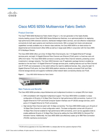
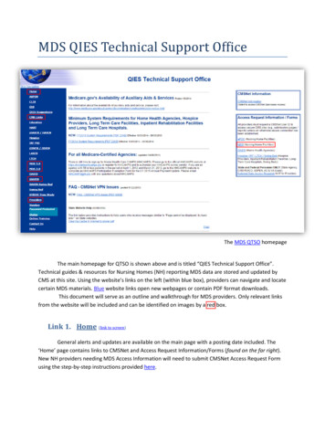
Up to three Wi-Fi connections are supported in Access Point mode. You can switchthe Device to Client mode to avoid this limitation.2. Client modeFigure 1. Wi-Fi details on IPhone 6In this mode, the Gateway connects to an existing Wi-Fi network. To switchto this mode from Access Point mode, or tune the settings, open the “Wi-Fi Client”page on the administration web site.— 12 —
The Gateway must have a fixed IP address. This can be done in the Wi-Fi routersettings; you can assign a fixed IP address by the MAC address of the Gateway printedon the “Wi-Fi Client” page. In this case, you can leave the default “Use DHCP” settingin the IP address configuration. Note that the Gateway has two different MACaddresses, one for the internal Access Point and one for connecting to other networks.You should use the MAC address from the “Wi-Fi Client” page.Or you can choose “Static IP” address and enter an IP, subnet mask and networkrouter address. In most cases, you can open the settings of the Wi-Fi network on asmartphone or PC, and copy the mask address and router address and select a freeIP address from this subnet. For example, if the router has the address 192.168.4.1(see Figure 1 on the previous page) and a smartphone has the address 192.168.4.3, youcan try 192.168.4.100. This is far enough from the address assigned to smartphone.In case of difficulty, contact your router administrator or refer to the routerdocumentation.The “Save” button saves settings to EEPROM, and they will be applied at the nextconnection to the Wi-Fi network. The “Save & Apply” button saves settings and triesimmediately to apply them if the Gateway is in Client mode already.Choose the network from the list or enter the name of a hidden networkin the “Other.” edit box and click “Connect”.If the Gateway was in Access Point mode before, it will shutdown the“YDWG” network after successful connection. Your client device(smartphone, laptop) will continue searching for a non-existing network,and you may need to change the Wi-Fi network manually and enterthe new IP address of administration web site in the browser.— 13 —
For example, you connect the Gateway to the network “Yacht” and specify 192.168.1.100as the address in the static IP address field. You should connect your smartphoneor laptop to the “Yacht” network and type http://192.168.1.100 in the web browserto open administration web site.3. What to do if the Device is not accessibleThere many possible reasons why you may not be able connect to the Gatewayafter changing settings. Check the following: was the IP address configured before switching to Client mode?what is the Gateway state according the LED signals? (see VI.)is your smartphone or laptop connected to the same Wi-Fi networkas the Gateway?what IP address was assigned to the Gateway? (in Wi-Fi router settings)If you cannot diagnose what is wrong, you can reset the Device’s settings (see VII.)and the Device will be returned to Access Point mode. You can connect to “YDWG”network again and try to change the settings one more time.4. Other important settingsWe also strongly recommend changing the default password for accessto the administration web site. It can be done on the “Administration” page.Access to port 80 (default port of web server) can be limited in some networkconfigurations, and you may change the port on the “Home” page to another, 8000 forexample. In this case, you will need to type http://192.168.4.1:8000 in the address barof browser instead of http://192.168.4.1 to get access to the administration web site.— 14 —
IV. Configuration of Application ProtocolsFigure 1. Settings of OpenCPN applicationMost marine applications support both TCP and UDP network protocols. TCPis a connection-oriented protocol. This means that the receiver must confirmreception of data before it gets the next packet of data, otherwise the sender repeatsthe transmission after a timeout. So, the second TCP connection doubles the network— 15 —
traffic and CPU load, despite the fact that both clients receive the same data.UDP is a connectionless protocol; any number of clients can listen to data broadcastedfrom a specified port without any additional load on the server and without increasingthe actual network traffic. We recommend using UDP protocol where possible, becausethe resources of the Device’s CPU are limited.The Gateway supports RAW and NMEA 0183 data protocols. The RAW protocolis supported in Expedition 10 and CAN Log Viewer. This protocol is very simple,open and also supported by our USB Gateway YDNU-02. We hope that this protocolbecomes popular among software developers.NMEA 0183 is supported in virtually all marine applications. The Gateway containsa bi-directional converter between NMEA 0183 and NMEA 2000 and has a flexiblesystem of message filters (see V).On the “NMEA Server” page on the administration web site you can set up to threeserver ports (see Figure 2 on the next page). If TCP network protocol is selected,up to three connections (from three different applications on one device, or from threedevices with one marine application running on each) are allowed at the same time.So three servers allow nine connections in total.In the case of using UDP protocol, the number of devices or applications used the dataport is not limited. We recommend using UDP protocol when possible.Server port can be configured as bi-direction, read-only (Transmit Only) or writeonly (Receive Only). We recommend configuring data ports as read-only if possible,to prevent network flooding from incorrectly configured applications.— 16 —
Server 3 also supports “Debug” data protocol, designed to diagnose issues withsoftware applications. This protocol is described in chapter VIII.Figure 2. Gateway server settings— 17 —
With the factory settings, Gateway has the 1st server enabled and pre-configureduse TCP port 1456 and the NMEA 0183 data protocol. To connect your applicationto the Gateway with factory settings: connect your laptop or mobile device to YDWG network;set the IP address 192.168.4.1 in the application settings;specify the TCP protocol and port 1456 in the application settings.To use the gateway with a Navionics Boating App, no settings are required in the app,but some changes are required in the Gateway configuration: configure one of the Gateway servers to use UDP port 2000 and NMEA 0183data protocol;connect your smartphone or tablet to the Gateway’s Wi-Fi network.Some versions of Nobeltec MaxSea and TimeZero ignore sentences with «--» talkerID (used by default in previous firmware versions) and you need to change itto something else, for example, to «YD» (see X.2).The settings on the “NMEA Settings” page are designed to control an autopilotby NMEA 0183 protocol and tune NMEA 0183 output settings, see chapter X.for details.— 18 —
V. NMEA 0183 and NMEA 2000 Message FiltersThe Device has 14 filter lists which allow limiting the set of messages passed fromthe NMEA 2000 network to a PC or mobile application (transmit filters) and messagespassed from the application to the NMEA 2000 network (receive filters).Each NMEA server has four filter lists: two for incoming and outgoing NMEA0183 messages, two for incoming and outgoing NMEA 2000 messages (usedfor RAW protocol). Which filter is used depends on the server data protocol settingsdefined on the “NMEA Servers” page. There are 12 filter lists in total.The Device also has two “Global” filter lists, which define what NMEA 2000 messagescan be passed from the network to internal NMEA servers and what NMEA 2000messages can be sent by internal NMEA servers to the NMEA 2000 network.Each filter list has a switchable type: WHITE or BLACK. A message is passedthru the WHITE filter if it contains a record matched with a message. And the reversefor BLACK. In the factory settings, all filter lists are empty and are of BLACK type,so all messages are passed through the filters.1. Syntax of NMEA 0183 filtersNMEA 0183 filters contain 3-char NMEA 0183 sentence formatters separatedby a space character. According to the standard, an NMEA 0183 sentence starts witha or ! symbol, followed by a two-character talker ID and a 3-char sentenceformatter. These elements are followed by data fields (after the comma).The sentence is finished by a check sum after the * (asterisk) symbol.— 19 —
Gateway with factory settings using «YD» talker ID, it can be changedon the “NMEA Settings” page (see X.2). The Device uses 3-char sentence formattersonly for filtering. The following sentences matches to GLL and VDM records (sentenceformatters): M,1,1,,B,ENk smq71h@@@@@@@@@@@@@@@@@ MeR6 7rpP00003vf400,4*5FExample of correct NMEA 0183 filter text:GLL VDM DPT2. Syntax of NMEA 2000 (RAW protocol) filtersYou should be familiar with the NMEA 2000 Standard (can be purchasedfrom National Marine Electronics Association, www.nmea.org) to operate withNMEA 2000 filters.These filters actually contain pairs of 29-bit message identifiers and a mask.The identifier is compared by processing the NMEA 2000 message identifierand the second value (mask) defines the comparison concerning which bitsare significant. The identifier contains a PGN (Parameter Group Number, describedin NMEA 2000 Standard) and a source device address. You can use decimaland hexadecimal numbers (which start with a 0x prefix).To simplify defining filters, it is also allowed to set filters using PGN only. The filterstring contains records separated by comma. Records contain an identifier and maskseparated by space, or a PGN number.— 20 —
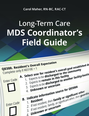
Example of correct filter:0x1FD0700 0x1FFFFFF, 130310, 1 255, 130311This filter matches with messages with PGN 130311 (0x1FD07) sent by the device withaddress 0, PGN 130310 (sent by any device), messages sent by a device with address1 (“1 255” is another form of the record “0x0000001 0x00000FF”), and PGN 130311(sent by any device).3. Configure filtersWe recommend using Gateway filters only when filtering is not available in softwareapplications (unfortunately, this is not rare in mobile applications). Read chapter VIIIto learn how to tune filter settings.To configure a filter, open the “NMEA Filters” page on the administration web siteand select it with “Server”, “Data Protocol” and “Filter” combo boxes. Switch the filtertype to required, enter a filter string and click “Update” (to discard changes just switchto another filter). On update, the Device parses the string and returns the effectivesettings back. Incorrect strings are ignored by the Device.Changes take effect immediately, and if you have diagnostics data opened in anotherbrowser window (see VIII), you can monitor the effect of changes in real time.— 21 —
Figure 1. Filter configuration page— 22 —
VI. LED SignalsThe Device is equipped with a bi-color LED that indicates the Device’s state. At poweron, the Device produce a single green flash to indicate that power is y is configured touse its own Wi-Fi networknamed “YDWG” (SSID),Access Point mode.The Gateway is configuredto use the boat’s existingWi-Fi network, Clientmode.2Wi-Fi StateThe state of Wi-Fi link isnormal.Wi-Fi link is not establishedyet or some error happen(cannot connect to existingWi-Fi network, wrongpassword, etc.).3TCPConnectionsSome clients are connectedtoGatewayservicesby TCP protocol. Whenthe administration web siteis browsed, the connectionexists only a short periodwhen page is downloadingfrom the server.No TCP connections areopen (but applicationscan receive data by UDPprotocol at the same time).4NMEA 2000StateData was received orsent to the NMEA 2000network.No data was received orsent to the NMEA 2000network— 23 —
During normal operation, the Gateway produces a series of four flashes every5 seconds.With the factory settings, the Gateway should flash GREEN-GREEN-RED-GREEN,and when you open the administration web site in the web browser(http://192.168.4.1), the Device will blink all green while pages are loading.LED signals during device reset using the hidden reset button are describedin chapter VII.LED flashes during firmware update procedure are described in chapter IX.— 24 —
VII. Reset of Settings and Hardware ResetInsert the paper clip (at a right angle to the device face) in the small holein the end plate of the Gateway. The LED of the Gateway will constantly shine redwhen the hidden button under the hole is pressed.Wait 2-3 seconds and the LED will change from red to green. Release the buttonto reset the Device’s settings. Otherwise, the LED will become red 2-3 seconds later.Keep the button pressed ten seconds more, and the LED becomes green. Releasethe button to complete a hardware reset of Device. Alternatively, wait two seconds,and the LED color returns to red.Note that nothing happens if you release the button when the LED signal is red.The settings reset occurs if you release the button during the first green light period,and the hardware reset occurs on the second period.During settings reset, the Device changes all settings to factory values (returnsto Access Point Mode, network SSID to “YDWG”), and the Device will produce fastgreen flashes for 2-3 seconds, then reboot.During hardware reset, the Gateway returns to the firmware version programmedat the factory (the Device always keeps a copy of this version in EEPROM)and to the factory settings. LED signals during firmware updates are describedin chapter IX.Hardware reset is normally not required. It can be used for firmware rollback.— 25 —
VIII. Recording of Diagnostics DataDiagnostics designed to troubleshoot issues with software applications. A log containsall sent and received NMEA 2000 messages and all data sent and received fromand to the NMEA server #1 port (see IV). The NMEA server #3 can be configured tosend log data in a real time to a web browser or terminal application.1. Configure problem application to use port of server #1.2. To get the diagnostics log, configure server #3 port to the “Debug” data protocol(it is TCP network protocol).3. If the Gateway has the address 10.1.1.1 and server #3 port has a number 1500,type http://10.1.1.1:1500 in browser address bar (experienced users can alsouse terminal applications to get data from this port).— 26 —
Figure 1. Chrome browser with logPress the “Stop” button in the browser (or the Esc button in some browsers) whenenough data is downloaded and saves the log to disk. Some mobile browsersdo not allow saving of files and we recommend using a laptop or PC to recorddiagnostics data. Some web browsers may try to download the web page againwhile saving. In this case, you can use the clipboard (Copy All and Paste commandsof operating system) and text editor to save the data to a file.— 27 —
IX. Firmware UpdatesYou can check the current firmware version at login or on the home pageof administration web site (see III) or in the Device information in the listof NMEA 2000 (SeaTalk NG, SimNet, Furuno CAN) devices or in the common listof external devices on the chart plotter (see the third line in Figure 1).Usually access to this list is located in the “Diagnostics”, “External Interfaces”or “External devices” menu of the chart plotter.We recommend updating the firmware from a laptop or PC. You can downloadthe latest firmware version from our web site: http://www.yachtd.com/downloads/You should open the downloaded .ZIP archive with an update and copy the WUPDATE.BIN file to the disk. The README.TXT file inside the archive can contain importantinformation regarding the update.1.2.3.4.Log in to the administration web site.Open the “Firmware Update” page.Click the “Choose File” button and locate the WUPDATE.BIN file on the disk.Click the “Update the firmware” button.The Firmware upload takes 20 – 40 seconds. After this period you’ll get a messagethat the update is started. You will see chaotic flashes of the LED for 40 – 60 seconds,and the Gateway will be rebooted when the update procedure is finished.The firmware update cannot damage the Device and all settings will remainintact (unless otherwise stated in the README.TXT file provided with— 28 —
the update) For example, if the update procedure is interrupted due to power failure,it will be re-started at the next power on.You can roll back all firmware updates and return to the factory firmwarewith hardware reset (see chapter VII).Figure 1. Raymarine c125 MFD devices list with the Device (YDWG-02)— 29 —
X. NMEA Settings and Autopilot ControlThis chapter describes how to control NMEA 2000 (SeaTalk NG) autopilot fromthe application using NMEA 0183 protocol and the settings available on the “NMEASettings” page of the administration web site.1. True wind calculationThe wind sensor always measures apparent wind; true wind angle is calculated usingSOG or STW data and true wind direction requires COG or heading. A chart plottercan join all these data and send calculated values to NMEA 2000, but usually TWD,TWA and TWS are not available.Historically, STW/HDG are used to calculate true wind. However, this is not correctin places with strong current, and the «true» value of true wind can be obtainedusing the SOG/HDG pair. Therefore, our gateways offers four options: SOG/HDG(if you love truth), SOG/COG (if you have GPS only), STW/HDG (if tradition is mostimportant), or you can disable calculations. In the last case the gateway reports truewind data only if they are calculated by another device available on NMEA 2000network.The default setting «Any» means that the gateway will detect what data are availableon the network and will calculate true wind data using the best possible option.2. Talker IDYou can configure the talker ID (two next characters after or ! sign) forNMEA 0183 output sentences. The default setting for the talker ID is «YD»and gateway sentences looks like:— 30 —
YDWPL,5441.1350,N,02014.8640,E,005*7A YDRTE,1,1,c,My Funyy Route,001,002,003,004,005*10Some versions of Nobeltec MaxSea and TimeZero (PC and iPad versions) ignoresentences with talker ID «--» (was used by default in previous firmware versions).3. Autopilot controlModern autopilots have the following modes: Standby. In this mode, autopilot is not engaged to the vessel control.Auto. The autopilot has a fixed course to steer.Wind. The autopilot steers the boat at a specified angle to the wind.Waypoint. The autopilot steers the boat to the specified waypoint.Route or Track. The autopilot steer the boat by a specified route.The difference in the last two modes is that autopilot not only maintainsthe right direction to the waypoint, but also tries to follow the line from the previousto the next waypoint.Note that Gateway server port must be configured to work in both directions(“Transmit Only” in factory settings) to allow control of autopilot from the application.When NMEA 2000 autopilot is controlled from an NMEA 0183 application, it mustreceive: position of the destination waypoint (from RMB sentence);course from the position to the destination waypoint (APB and/or RMB);cross track error, means the distance and direction from the current position— 31 —
to the route (APB and/or RMB and/or XTE).Depending on the implementation, the NMEA 2000 autopilot can also usethe following data (and not only): vessel heading (HDG sentence), but in most systems the heading sensoris connected directly to the autopilot;rate of turn (ROT sentence);position, course and speed over ground (RMC sentence).To control the autopilot, Gateway should receive APB and RMB sentences fromthe application. Gateway also needs to have magnetic variation data, whichcan be obtained from HDG or RMC sentences or from the NMEA 2000 messages(must be turned on in the Gateway settings).If your NMEA 2000 network has GPS data, it can use data already availableon NMEA 200
IV. Configuration of Application Protocols 15 V. NMEA 0183 and NMEA 2000 Message Filters 19 VI. LED Signals 23 VII. Reset of Settings and Hardware Reset 25 VIII. Recording of Diagnostics Data 26 IX. Firmware Updates 28 X. NMEA Settings and Autopilot Control 30 XI. Web Gauges of Administrative Web Site 35 APPENDIX A. Troubleshooting 37


![Smarter Battery Crack [2022-Latest]](/img/13/eliamari.jpg)