Transcription
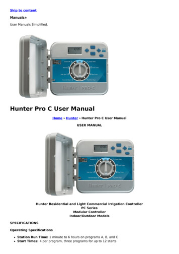
HARDWARE & SOFTWARE USER MANUALHardware & SoftwareUser Manual(April 2017, Rev. 1)MANUFACTURED and MARKETEDAVG/EZAutomation4140 Utica Ridge Rd. Bettendorf, IA 52722-1327April 20171 Page
HARDWARE & SOFTWARE USER MANUALWARNING!Programmable visualization products such as the EZ iMarquee are not fail-safe devices and as such must not beused for stand-alone protection in any application. Any reliance on these devices for equipment or personnel safetyis unwarranted.WARNING: EXPLOSION HAZARD — do not disconnect equipment unless power has been switched off or the area isknown to be non-hazardous.TrademarksThis publication may contain references to products produced and/or offered by other companies. The product andcompany names may be trademarked and are the sole property of their respective owners. AVG Automationdisclaims any proprietary interest in the marks and names of others.EZ iMarquee Getting Started Guide Copyright 2017, AVG AutomationAll Rights ReservedNo part of this manual shall be copied, reproduced, or transmitted in any way without the prior written consent ofAVG Automation. AVG Automation retains the exclusive rights to all information included in this document.The diagrams and examples in this user manual are included for illustrative purposes only. The manufacturercannot assume responsibility or liability for actual use based on the diagrams and examples.April 20172 Page
HARDWARE & SOFTWARE USER MANUALTable of ContentsPurpose of this Manual. 5Manual Organization. 6Chapter 1: Getting Started . 71.1Installing the EZ iMarquee – Overview . 71.2What You Need to Get Started . 71.3Need Help? . 8Chapter 2: Models and Equipment . 92.1Product Overview for the EZ iMarquee . 92.2EZ iMarquee Part Numbering System . 102.3EZ iMarquee Features . 102.4EZ iMarquee Other Parts . 112.5Unit Specifications . 11Chapter 3: Installation . 133.1Installation Considerations . 133.2Wiring and Connections . 153.3Serial Communication Ports . 183.4Power Connection . 213.5Mounting Overview . 213.6Power Up Messages. 23Chapter 4: EZ iMarquee Editor software. 244.1System Overview . 244.2EZ iMarquee Programming Software . 244.3Creating a new Project . 254.4Creating Messages . 264.5Message Options . 304.6Tags . 344.7Marquee Serial Network Setup . 414.8Ethernet Setup . 424.9Project Attributes . 42April 20173 Page
HARDWARE & SOFTWARE USER MANUAL4.10Transferring Project to iMarquee . 434.11Upgrading Firmware . 44Chapter 5: PLC Communication Setup. 465.1Basic PLC Setup . 465.2PLC Serial Communication Setup. 475.3PLC Ethernet Communication Setup . 495.4Allen-Bradley Ethernet IP Setup . 505.5Automation Direct Productivity / Direct Logic / Do-More Setup . 515.6Siemens S7 ISO Setup . 525.7Modbus TCP/IP Setup . 535.8GE PLC Communication Setup . 54April 20174 Page
HARDWARE & SOFTWARE USER MANUALPurpose of this ManualManual Title: EZ iMarquee Hardware & Software User ManualPurposeThis EZ iMarquee User Manual will give you all the information necessary to install the EZ iMarquee in a fixedlocation in your work environment, and how to wire it to other components in your control system. Included aremounting diagrams and instructions for installation, Connections and Wiring requirements, MaintenanceInformation, Programming Information, and Troubleshooting.This manual is a good reference guide for those who install the Marquee, as well as those who program it. If youunderstand the EZ iMarquee, or Marquees in general, you can find all the information you need to start andmaintain your system in this manual.The following table provides you with updated information. If you call technical support with a question about thismanual, please be aware of the revision number and date.Revision1.0AuthorDIDateApril 2017Pages EffectedAllDescription of ChangesOriginal Release of ManualTechnical SupportIf you need assistance, please call our technical support at 1-877-774-3279 (EASY) or FAX us at 1-877-775-3279.You can also email technical at techsupport@ezautomation.net.April 20175 Page
HARDWARE & SOFTWARE USER MANUALManual OrganizationThe information below provides an overall description of the topics covered within this manual.Chapter 1: Getting StartedProvides Manual Organization and lists what you need to get started to display messages. Gives you a quickreference to get familiar with your EZ iMarquee. Discusses how to get help with questions you mightencounter and how to contact Technical Support.Chapter 2: Models and EquipmentProvides you with a table listing the various models, their part numbers and special features. Lists theimportant features and hardware specifications for different models.Chapter 3: Installation, Wiring and Connection InformationProvides information about preparing the marquee for operation such as setting the DIP switches,connecting Power and how to interface EZMarquee for Serial communication. Shows the mounting andcutout dimensions for the different models. Explains the different ways to mount the marquee. Shows thesetup screens displayed after initial power up of the display.Chapter 4: EZ iMarquee Editor SoftwareProvides information about how to download the EZ iMarquee Editor software. Also provides informationabout how setup a new project, create messages, and download the project to the EZ iMarquee.Chapter 5: Communication Setup with various PLCsQuick guide to set up the communication with different PLCs over EthernetAllen-BradleyKoyo by Automation DirectSiemensEZ PLCGeneral Electric (GE)April 20176 Page
HARDWARE & SOFTWARE USER MANUALChapter 1: Getting Started1.1 Installing the EZ iMarquee – OverviewThis section is designed to take you through a quick start on how to use the EZ iMarquee. It assumes that youare a first-time user of EZ iMarquee. By following the 3 Simple Steps, you will be creating and displayingmessages on your EZ iMarquee in no time.MountingThe EZ iMarquee is a suspension mount unit. Please refer to the beginning ofChapter 3: Installation for environmental factors, hardware requirements andinstructions.Connections & WiringOnce your EZ iMarquee is mounted, you are ready to connect your unit to the powersource, PLC, and other devices. Note that the EZ iMarquee is an AC powered unit(120/240 VAC). For more details, refer to Chapter 3: Wiring and Connections.Connections & WiringDownload and install the EZ iMarquee Editor software, refer to Chapter 4. Connectyour EZ iMarquee to a PLC, refer to Chapter 5. Have your EZ iMarquee startdisplaying messages!1.2 What You Need to Get Started1.2.1 Hardware EZ iMarquee display110/220 VAC input cord with stripped wire on one endEZ iMarquee Programming Cable (EZ-PGMCBL) unless you purchase the EZ iMarquee equipped with theexclusive EZWifi Module.Ethernet Cable (if applicable)Serial (RS232/RS422/RS485) PLC Communication Cable (based on PLC)PC requirements:o PC with a mouse and serial port (USB port may be used with Serial to USB converter [Aten,Belkin, or Tripp Lite recommended])o Standard Windows XP, Windows 7, or Windows 10 operating system.User ManualApril 20177 Page
HARDWARE & SOFTWARE USER MANUAL1.2.2 Software EZ iMarquee Editor software (version 1.0 or higher)The EZ iMarquee programming software, can be downloaded FREE of cost by following these steps:1.2.3.4.5.Go to www.ezautomation.com.au.Click on Downloads at the top of the page.Scroll down to EZ iMarquee section.Right click on the appropriate software title and save it to your computer.Install the EZ iMarquee Editor software on your computer.1.3 Need Help?1.3.1 Tech SupportIf you need assistance, please call our technical support at 61-2-9482 4000You can also email technical at info@ezautomation.com.au You can also visit our website atwww.ezautomation.com.au1.3.2 DocumentationQueriesInformation ResourceiMarquee Mounting and InstallationEZ iMarquee Hardware & Software User Manual (this manual)iMarquee Wiring and ConnectionsiMarquee PLC ConnectivityiMarquee ProgrammingEZ iMarquee Getting Started GuideEZ iMarquee Hardware & Software User Manual (this manual)EZ iMarquee Getting Started GuideEZ iMarquee Hardware & Software User Manual (this manual)EZ iMarquee Getting Started GuideEZ iMarquee Programming Software HelpNote: The EZ iMarquee Getting Started Guide is a simpler step by step process for setting up the EZ iMarquee. Allthe information that is in the EZ iMarquee Getting Started Guide is also included in the Hardware User Manual (thismanual).April 20178 Page
HARDWARE & SOFTWARE USER MANUALChapter 2: Models and Equipment2.1Product Overview for the EZ iMarqueeThe EZ iMarquee (EZ Intelligent Marquee) is a Master Marquee model; it monitors connected devices, suchas PLCs, and is capable of issuing string messages or Triggering messages based on external events to othermarquees and devices.The EZ iMarquee is the most sensible marquee for stand-alone and Plant-wide communication displays withlarge character sizes so that the messages are visible up to 400 feet. Character visibility can be enhanced byscrolling or blinking the message.The EZ iMarquees are offered in 5 different models, each with Tri-Color LEDs, to suit every application. Youcan display messages in 2”, 4”, 6”, 8” and 8” Narrow characters. All EZ iMarquee models are capable ofcommunicating over RS-232, RS422, and Ethernet communications.EZ iMarquees can be interfaced with PLCs, PCs, and embedded controllers. All EZ iMarquees support ASCIIprotocol. You can also take advantage of EZ iMarquee’s International Character Set to display yourmessages in multiple international languages.2” characters - readable from 100 feet4” characters - readable from 200 feet6” characters - readable from 300 feet8” characters - readable from 400 feet8” Narrow characters - readable from 400 feet1L refers to one line or “row” that equals 20 characters (each 2” high). 20C refers to 20 characters, all ofwhich are 2” high.EZ iMarquees are available in several sizes. The smallest size is called the 1L20C. The other sizes aremultiples of the smallest size, such as the 4L20C (shown above), and the 2L40C (which has two lines of textbut is twice the length; thus supporting twice the number of 2” characters per line), etc. See chart on Page Xfor a complete listing of sizes, with their full range of text possibilities.April 20179 Page
HARDWARE & SOFTWARE USER MANUAL2.1.1 Physical CharacteristicsEZ iMarquees are enclosed in NEMA 12 housing, with NEMA ICS 2-230 level of electrical noise immunity.Three grommets are provided for routing wires through the back access plate. The connectors and set-upswitches can be accessed by removing the back access plate.EZ iMarquee can be mounted in three different ways. It can be mounted on a wall, ceiling or on top of themachine depending upon the application. Chapter 3 describes the various ways to mount and install the EZiMarquee.2.1.2 MessagesHow messages look depends on the way they are sent. Messages have options that determine messageoutput and visual appearance. A network of two groups of EZ iMarquees with 8 marquees in each group canbe set up. When the message contains group and unit number information, the message can be displayedon one, some, or on all of the EZ iMarquees.The EZ iMarquee also features International Character Sets. This option is switch-selectable to allowmessage display in U.S., English, French, Danish, Swedish, German, Cyrillic, or Japanese Kana.2.1.3 Where to Use EZ iMarquee DisplayUsing EZ iMarquees is an excellent way to keep workers in touch with the manufacturing process via thefollowing: Monitor Productivity of each machine, line, or the whole plant Communicate Alarm and Safety Messages Provide Continuous Reports on Factory Conditions2.2EZ iMarquee Part Numbering SystemEZiMT - XLYYCSize of display:XLYYC, where “X” the number of lines of text, and “YY” the number of characters per line. For example:4L20C 4 lines of text, with a maximum of 20 characters per line. See chart in section 2.5.2 for a fullbreakdown of unit sizes, with their display features, dimensions, weights, etc.2.3EZ iMarquee Features 2” to 8” Tri-Color charactersInternational Character Set5 Available Models (1 Line 10 Char to 4 Line 40 Char)NEMA 12Pre-Matched LEDs24 hour Burn-in testedApril 2017 110/220 VAC Power Input voltageUL, CUL, CE, CSA Approval (pending)Stationary, Scrolling and Blinking Messages100,000 Hour rated lifeMixed Character sizes on one Line10 P a g e
HARDWARE & SOFTWARE USER MANUAL2.4EZ iMarquee Other PartsThere are replacement parts and other optional equipment available to customize or upgrade the EZ iMarqueeto fit your application. The tables below provide you with a list of this equipment. Instructions, if necessary,on how to install this equipment to upgrade your unit are also provided.2.5PartDescriptionNotesEZ iMarquee Programming SoftwareSoftware to program EZ iMarqueeDownload at www.ezautomation.netGrommetsConnectors on the EZ iMarquee back plateOrder by request by calling 1-877-774-3279Back PlateEZ iMarquee back plate with grommetsOrder by request by calling 1-877-774-3279Mounting BracketsMounting Brackets for the EZ iMarqueeOrder by request by calling 1-877-774-3279Phoenix ConnectorsPhoenix connects for plug-in Terminal BlockOrder by request by calling 1-877-774-3279Unit SpecificationsGeneral Specifications for all the EZ iMarquee models are provided in the following pages.2.5.1 General Specifications for all EZ iMarqueesEnclosure:Power Supply:Power:Operating Temperature:Storage Temperature:Humidity:Electrical Interference:Electrical Tolerance:Vibration:Shock:April 2017NEMA 12 (Indoor Only)110 VAC (102-132) 47-63 Hz / 220 VAC (194-250) 47-63 Hz28-180 Watts (Depending on size)0 to 55 C (32 to 131 F)-40 to 90 C (-4 to 140 F)10 – 95% RH, non-condensingNEMA ICS 2-230 Showering Arc TestANSI C37.90a-1974 (SWC) Surge Withstand Capability Test5 to 55 Hz 5G for 2 hours in the X, Y, & Z axes20G for under 12 mSec in the X, Y, & Z axes11 P a g e
HARDWARE & SOFTWARE USER MANUAL2.5.2 Marquee Dimensions, Weights, and Display Options by UnitThis table shows the dimensions and weights for each Marquee model, according to the housing materialselected. It also shows all standard message text sizes and the maximum number of lines and characters foreach character height supported. “N” denotes “Narrow” characters.April 2017Part NumberDimensions: W x H x DWeight2L10C18.87” x 5.67” x 2.75”2.8 lbs.2L20C36.04x 5.67” x 2.75”3.0 lbs.4L20C36.58” x 10.47” x 2.755.0 lbs.2L40C72.45” x 5.67” x 2.75”15 lbs.4L40C72.45” x 10.47” x 2.75”30 lbs.Possible Text Configuration(at Uniform Character Height)2” char: 2 lines of 10 characters4” char: 1 line of 5 characters2” char: 2 lines of 20 characters4” char: 1 line of 10 characters2” char: 4 lines of 20 characters4” char: 2 lines of 10 characters6” char: 1 line of 6 characters8” char: 1 line of 5 characters8N” char: 1 line of 10 characters2” char: 2 lines of 20 characters4” char: 1 line of 10 characters2” char: 4 lines of 40 characters4” char: 2 lines of 20 characters6” char: 1 line of 13 characters8” char: 1 line of 10 characters8N” char: 1 line of 20 characters12 P a g e
HARDWARE & SOFTWARE USER MANUALChapter 3: Installation3.1Installation ConsiderationsAVG products have been designed and tested for operation in the most demanding industrial environments.Modern solid-state industrial controls are complex electronic equipment that operates at low levels ofvoltage and current, coexisting with components that operate at much higher levels of power. Thedifference in operating power characteristics between the high and low power control devices creates thepossibility of unwanted signals being generated causing interference. The interference, which is a byproduct of electrical noise, is not present at all times. However, it appears at random and during briefperiods of time can cause disruptions and errors in the operation of a control system.Enhancement of a system’s noise level immunity, and its tolerance to other environmental hazards can beaccomplished by following proper system installation guidelines. The recommendations that follow are of ageneral nature and constitute good, solid state industrial installation practice.3.1.1 General Environmental Installation ConsiderationsAvoid installing your Marquee in areas where the following conditions may exist: Environmental temperatures above or below those specified by the system being installed Prolonged exposure to humidity and liquids which may be sprayed or splashed on the equipment Dusty environments where airborne particles may accumulate on equipment causing reduction of heatdissipation, and reduction in effective electrical spacing between components Areas of excessive vibration Areas of high-radiated electrical noise, such as near fields of transmitting antennas and areas in closeproximity of arc welding stations3.1.2 Environmental SpecificationsThe following table lists the environmental specifications that generally apply to the iMarquee. However I/Omodule operation may fluctuate depending upon the ambient temperature and your application.ParameterOperating TemperatureStorage TemperatureHumidityVibration ResistanceShock ResistanceElectrical NoiseApril 2017Ratings0 to 55 C (32 to 131 F)-40 to 90 C (-4 to 140 F)10 – 95% RH, non-condensing5 to 55 Hz 5G for 2 hours in the X, Y, & Z axes20G for under 12 mSec in the X, Y, & Z axesANSI C37.90a-1974 (SWC) Surge Withstand Capability Test13 P a g e
HARDWARE & SOFTWARE USER MANUAL3.1.3 AC Line NoiseThe AC power available in house outlets and at sub-stations powering industrial and commercialapplications is generally generated at a power station miles away from the point of usage. The power is“noise” free at the time it is being generated, and meets all specifications for amplitude, frequency,harmonic distortion and others. However, the same specifications cannot be guaranteed at the point ofusage, due to the disruptive factors associated with the transmission from generator to consumer.While the generated power output starts its journey “clean,” and free of noise, it is “polluted” by radio andTV frequencies, spikes from reactive kickbacks due to switching heavy inductive and capacitive loads intransmission lines, and from other interference.As a result, critical and sophisticated electronic controls may malfunction; false triggering, user program lossand/or modification may occur and even catastrophic failure.In view of the problems associated with AC power, it is strongly recommended the source, transmission andfinal end use be given stringent consideration before any commitment to supply the system is given. Sometypical problems in power line usage are:Blackouts:This is the total loss of power. Generally, they are easy to detect and if a situationarises where they cannot be tolerated then an uninterrupted power supply (UPS)should be used.Brownouts:This occurs when there is a reduction in line voltage amplitude. If this reductionfalls within operating limits, no adverse effects will be experienced. However, if theyare frequent and severe, a UPS system should be considered.Voltage Fluctuations:These are amplitude variations (rapid or slow) and can occur above or below thespecified limits. Overvoltage conditions may damage equipment if the duration of thevoltage condition is lengthy. It may cause disruptions, data loss, and productiondowntime.Noise Spikes:Noise spikes and other unwanted signals superimposed on the AC line voltagewaveform are the most common problems associated with the distribution of thepower from its grid system. The amplitude of these signals can be from severalhundred to a few thousand volts and the pulse width from about one to 200microseconds. Because of their short duration and random occurrences, theseharmful signals are difficult to detect.April 201714 P a g e
HARDWARE & SOFTWARE USER MANUAL3.1.4 Dealing with AC Line and Other Electrical NoiseThe best option to effectively eliminate or greatly reduce voltage fluctuations, spikes and line noise isthrough the use of isolation, constant voltage, or power line conditioner transformers.Isolation transformers are passive devices that do not have DC paths between the circuits they isolate. Thetransformer provides attenuation to spikes and common mode noise, but has virtually no effect ontransverse mode noise and does not provide protection for voltage fluctuations.Constant voltage transformers are static Ferro-resonant transformers that can accept fluctuating AC voltageinput (within a specified range) and maintain a constant voltage output. The transformers provide goodattenuation to transverse mode type noise, however, are ineffective for attenuation of common mode typesignals.Power line conditioning transformers provide good line regulation and are effective in providing attenuationto both common and transverse mode types of noise.All of the mentioned transformer types are available by various manufacturers and they come in differentvarieties of operating voltages, power ratings, and frequencies.Make sure that the 110-220VAC Power Source for the Marquee is a clean noise-free power source used forlow voltage control systems as described above. It should be isolated from heavy inductive or RF loads such asmotors, motor starters, and welding and other RF equipment. Marquee’s power source should be either thesame as, or of the same quality, as that used to power your PLC.The power cable and unshielded communication cable must be run in a separate conduit or wiring harness.The shield at both ends should be connected to the Earth Ground Terminals to minimize extraneouselectrical noise pick-up.3.2Wiring and ConnectionsThis section of the manual provides information about preparing the marquee for operation, such as settingthe DIP Switches, connecting power and preparing to interface the Marquee for serial communication.3.2.1 Accessing Connectors and SwitchesThe Marquee has an Access/Cover plate on its backside. This is a gasket cover plate with three sealedgrommets for power, serial communication cable, and Ethernet cable. The gasket and the grommet seal mustbe intact to retain NEMA 12 rating. Once you remove the cover plate by removing the four access screws onthe plate, you have access to wiring terminals and 3 different DIP switch banks for marquee parameterselection.April 201715 P a g e
HARDWARE & SOFTWARE USER MANUAL3.2.2 Setting Up DIP SwitchesGroup and Unit Number: Each EZ Marquee is assigned a unit address. A unit address is programmed intoeach message to specify which unit or units should display that message. The unit address of an EZiMarquee is defined by the setting of the Dip Switch located inside the back panel under the access plate.This can be changed at any time to alter the address of the unit. Each unit address consists of twoidentifiers—a Group and a Unit Number. The unit addresses are divided into Group and Unit Numbers toallow the EZ iMarquee to address selected subsets of all the iMarquee displays connected to it.NOTE: The Unit Number and Group Number selection is applicable only if you use the RS232 port of the EZiMarquee. If using Ethernet then each iMarquee has an individual IP Address which is use for the same purpose.April 201716 P a g e
HARDWARE & SOFTWARE USER MANUAL3.2.3 DIP Switch 1 (SW1)DIP Switch 1 is preset from the factoryDO NOT touch DIP Switch 1 under any circumstances!3.2.4 DIP Switch 2 (SW2)The diagram below illustrates how to set up DIP Switch 2:3.2.5 DIP Switch 3 (SW3)The diagram below illustrates how to set up DIP Switch 3:April 201717 P a g e
HARDWARE & SOFTWARE USER MANUAL3.3Serial Communication PortsDIPSWITCHESThe EZ iMarquee has 3 different serial ports for communication. These 3 different serial ports each have adifferent functionality. Serial Port 1 (SP1) is used to communicate to iMarquee slaves. Serial Port 2 (SP2) isused to communicate with PLCs serially. And finally Serial Port 3 (SP3) is used to download projects to theEZ iMarquee and to setup the iMarquee IP address. The EZ iMarquee also has an Ethernet Port that can beused for both PLC communication and to download projects to the iMarquee.3.3.1 Serial Port 1 (SP1)Serial Port 1 (SP1) is pre-wired in the factory as shown below, i.e. Pins 1-2 on SP1 are jumped together. Thisjumper connects the serial port on the Message Controller board within the marquee, to the serial port ofthe Message Display board in the marquee. The jumper is required for the Marquee to display messagessent from the controller. This port IS NOT used for PLC communication or PC to iMarquee programming.This port can be used to connect a SLAVE marquee to the iMarquee over RS232.To connect a slaveunit to the masteriMarquee, please useterminal numbers onSP1:2 (Tx)3 (Rx)5 (GND)April 201718 P a g e
HARDWARE & SOFTWARE USER MANUAL3.3.2 Serial Port 2 (SP2)The SP2 connector is used
EZ iMarquee Programming Cable (EZ-PGMCBL) unless you purchase the EZ iMarquee equipped with the exclusive EZWifi Module. Ethernet Cable (if applicable) Serial (RS232/RS422/RS485) PLC Communication Cable (based on PLC) PC requirements: o PC with a mouse and serial port (USB port may be used with Serial to USB converter [Aten,
