Transcription
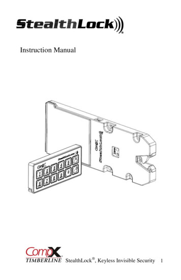
Technical Summary of Battery Energy Storage SystemsBased on the 2017 Massachusetts Electrical CodeThis document summarizes the new Article 706 in the Massachusetts Electrical Code (MEC). Article 706 Energy StorageSystems (ESS) was created to simplify and consolidate Articles 480 and part VIII of 690 in the 2014 edition of the MEC.The MEC is based on the National Electrical Code (NEC) with amendments. 1 Local codes and standards may supersedeany of the references below. Article 706 applies to all permanently installed ESS operating at over 50 volts AC or 60 voltsDC, and may be stand-alone or interactive with other electric power production sources. The primary focus of thisdocument is battery energy storage systems, and gives an overview of specific requirements within Article 706. Pleasenote that other code sections may also be relevant to storage systems.New Definitions and ESS ClassificationsEnergy storage systems are assembled components (one or more) that have the capability of storing energy for lateruse. These systems are classified as one of the following: self-contained, pre-engineered of matched components, orother. Self-contained units are the most recent technology.System Classifications (Article 706.4) 706.4 (1) ESS, self-contained All components of the ESS are contained in a single unit.706.4 (2) ESS, pre-engineered of matched components Components are not self-contained but are pre-engineered and field-assembled. These components aregenerally designed by the same entity and are intended to be installed together as a single system.706.4 (3) ESS, other Individual components that are installed in the field to create an ESS but are not necessarily designed bythe same entity.Figure 1. Self-contained energystorage system1Figure 2. Pre-engineered energystorage system of matchedcomponentsFigure 3. Other energy storage systemof individual componentsCommonwealth of Massachusetts. 527 CMR 1.00, 2012 edition. The Massachusetts Comprehensive Fire Safety Code and BaseCode. 2012. Available online: rev/527-cmr-index.html.1
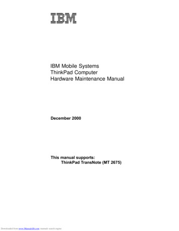
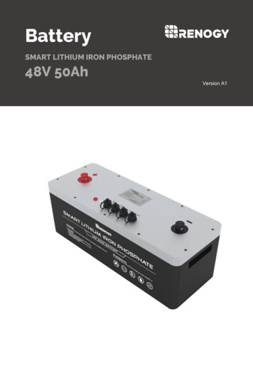
TechnologyTwo primary ESS technologies exist in wide usage today: DC coupled and AC coupled systems. When connected to asolar photovoltaic (PV) system, Article 690 provides additional requirements and diagrams to help identify key systemcomponents.DC Coupled Multimode SystemDC coupled is the oldest type of battery backup. The PV system directly charges a battery bank through a chargecontroller(s). The inverter supports protected loads through an internal transfer switch, drawing energy from thebatteries. A DC coupled system can be designed to be exclusively a backup system, to sell excess PV production back tothe grid, or perform both functions.Figure 4. DC coupled multimode systemAC Coupled Multimode SystemAC coupled systems are a newer concept in which a protected loads center is served by an inverter and its batterystorage; however, the PV component of the system operates as a grid-tied inverter, interconnected in the protectedloads center. AC coupled systems can be used without the presence of a PV system. The ESS is tied to the load panel andcan be charged with power from the grid. This is useful in application where loss of power is frequent or if peak demandprices are much higher than regular electricity demand prices.2
Figure 5. AC coupled multimode systemInstallation RequirementsDisconnecting Means (Article 706.7) 706.7 (A) ESS Disconnecting Means A means to disconnect all ungrounded conductors from an ESS is requiredto be readily accessible and within sight of the ESS.706.7 (B) Remote Actuation Controls can be used to activate the ESS disconnect. If the controls are notlocated within sight of the ESS, the location of the controls shall be fieldmarked on the disconnecting means.706.7 (C) Busways The disconnecting means can be incorporated into busways on a DCbusway system.706.7 (D) NotificationFigure 6. ESS disconnectingmeans A label is required to be marked in the field with the following values:1) Nominal ESS voltage2) Maximum available short-circuit current derived from the ESS3) The associated clearing time or arc duration based on the available short-circuit current fromthe ESS and associated overcurrent protective devices (OCPD) if applicable4) Date the calculation was performed3
Connection to Other Energy Sources (Article 706.8)ESS can be connected to other energy sources but must comply with Article705.12. This means the interconnection between an ESS and the grid isaccomplished the same way as PV. Depending on the situation, theinterconnection can be on the supply side (upstream of the main breaker) or loadside (downstream of the main breaker). The two most-common types of loadside connections are feeder taps and back-fed breakers in panelboards.A situation may arise during the installation of an ESS in which the capacity of aservice may be exceeded. In one scenario, as outlined in Figure 8, a dwelling withan existing 200A service, a supply side connection is performed. A 60A protectedFigure 7. Example of a supply-side connectionloads panel is installed, and some loads are relocated from the main servicepanel to the protected loads panel. The service now has the capability to draw260A for loads. Exception 3 to Article 230.90(A) may permit this; however, a service calculation will need to beperformed any time loads are added. This is rarely standard practice in the field.260A60A60A200AFigure 8. Example of supply-side connection with overloaded service conductors4
Directory Requirements (Article 706.11)Like other interconnected electric power production sources, ESSrequires “a permanent plaque or directory denoting all electric powerproduction sources on or in the premises.” It should be installed at eachservice location and the location(s) of all other power sources. Article110.21(B) is also referenced, outlining general requirements for fieldapplied hazard markings.Field-Applied Hazard Markings (Article 110.21(B)) Labels must be sufficient to withstand the environment involvedLabels shall be permanently affixed and shall not be handwrittenInformational note to follow ANSI Z535.4-2001, words, colors,symbolsCircuit RequirementsFigure 9. Permanent plaque indicating allpower sources on or in the premisesCircuit Sizing and Current (Article 706.20)Maximum current can be calculated using the nameplate ratedcurrent found on the ESS and inverter. Conductor ampacity andFigure 10. Example of ANSI Z535.4-2001 markingsovercurrent device ratings must not be less than the greater of (1)the nameplate current rating for the ESS or (2) the overcurrent device protecting the ESS.Overcurrent Protection (Article 706.21)ESS circuits must be protected with overcurrent devices. The rating of the overcurrent device shall not be less than 125%of the nameplate current found on the ESS and inverter. If fuses are used, means must be provided to disconnect them ifexposed to unqualified personnel. Where ESS terminals are more than 5 feet (or pass through a wall) from theconnected equipment, overcurrent protection is required at the ESS. Fuses and circuit breakers that are used on DCconductors shall be rated appropriately.Electrochemical Energy Storage SystemsInstallation of Batteries (Article 706.30)When installed in dwelling units, the voltage between conductors or toground must not exceed 100, unless the energized parts are notaccessible during routine maintenance. For series battery circuits over240 volts nominal between conductors or ground, a disconnectingmeans shall be provided to isolate segments, not exceeding 240 volts.The disconnecting means may consist of non-load-break bolted or plugin type. For systems over 100 volts, battery circuit conductors canoperate ungrounded, if a ground-fault detector and indicator isinstalled.Figure 11. 48-volt battery configuration in aresidential application5
Battery and Cell Terminations (Article 706.31)Some battery manufacturers require the use of antioxidant material on terminations to prevent corrosion. Theinstallation instructions must be followed to determine the appropriate type. For field-assembled intercell and interiorconnections, the conductor ampacity must be consistent with the maximum load conditions. Conductors that areinstalled between levels must not put mechanical strain on battery terminals.Battery Interconnection (Article 706.32)Within and around the battery enclosure, flexible moisture-resistant cables in sizes 2/0 and larger that comply withArticle 400, are permitted to be used. If flexible fine-stranded cables are used, they must be connected to terminals,lugs, devices, or connectors in accordance with Article 110.14. Figure 12 shows an example of welding cable that is notrecognized by Article 400, as well as an improperly-terminated fine-stranded cable on a standard lug.Figure 12. Left: Wiring method not recognized by Article 400Right: Fine-stranded cable on terminal not recognized by Article 110.14Accessibility and Battery Locations (Articles 706.33 and 706.34)The terminals of all cells or multicell units must be readily accessible. Article 100defines readily accessible as “capable of being reached quickly for operation,renewal, or inspections without requiring those to whom ready access is requisite totake actions such as to use tools (other than keys), to climb over or under, to removeobstacles, or to resort to portable ladders, and so forth.” The requirements of Article110.27 must be followed to guard exposed live parts. Where top terminal batteriesare installed on racks or shelves of cabinets, working space in accordance with themanufacturer’s instructions must be provided. If batteries are installed in adedicated room, gas piping is not permitted within the space.Figure 13. Batteries installed in acabinet with readily accessibleterminals and proper clearance6
APPENDIX 1 – Brief Listing of MEC Articles Relevant to Battery StorageNational Electrical CodeThe following is a brief listing of many articles and code references that should be consulted and applied to energystorage installations. This list does not include all articles pertaining to energy storage systems.Article 110.26Working spaces is discussed in general electrical equipment requirements. More guidance is give in subsequent articles.Article 230 ServicesThis article outlines the requirements to interconnect energy storage systems with the electric utility grid.Article 240 Overcurrent ProtectionThis article provides the requirements for overcurrent protection of conductors used in battery systems and ESS.Article 480 Storage BatteriesThis article provides direction on the support of, locations for, ventilation, and labeling requirements for stationarystorage battery systems. Currently, this Article and locally adopted codes provide the bulk of guidance for installingEnergy Storage Systems that may be outside of the scope of Article 706.480.1 Scope.This article applies to all stationary installations of storage batteries.480.4 Battery and Cell Terminations.Corrosion protection and intercell and interior conductors and connections ampacity are discussed here. Batteryterminal connections and mechanical strain are also discussed.480.7 DC Disconnect MethodsRequired labeling of disconnects.480.8 Insulation of BatteriesIf batteries are built with an electrically conductive container, they shall have insulating support if a voltage is presentbetween the container and ground.480.9 Battery Support SystemsDiscusses the need for support systems (racks) to be corrosive resistant in design, and be nonconductive, as well asaccess to terminals for readings, inspection and cleaning.480.10 Battery LocationsDiscusses ventilation requirements, guarding of live parts, spaces about battery systems and the requirements for topterminal batteries, as well as necessary illumination for battery working spaces.7
480.11 VentsVented cells shall be equipped with a flame arrester. Sealed cells that may accumulate an excessive pressure duringoperation, a pressure release vent shall be provided. These requirements are applied at a battery cell level, and are mostoften addressed at the manufacturing level, not the ESS design or installation levels.Article 690 Solar Photovoltaic (PV) Systems690.11 Arc-Fault Circuit Protection (Direct Current)Arc fault circuit protection is required on DC PV circuits (notable for DC coupled ESS).690.12 Rapid Shutdown of PV Systems on BuildingsAs this article is specific to PV systems, it does not directly apply to ESS. However, it may come down to local AHJinterpretation and require a conversation prior to system design.690.15 Disconnection of Photovoltaic EquipmentMaximum current is greater than 30A, and equipment disconnecting means shall be provided for isolation. (A) Location– within the equipment or within sight and within 10 feet of the equipment. (B) Interrupt rating shall be sufficient for themaximum short-circuit current and voltage that is available at the terminals of the equipment.690.41(B) System GroundingGround fault detection is required on DC PV arrays (notable for DC coupled ESS).690.55 Photovoltaic Systems Connected to Energy Storage SystemsPolarity marking of conductors is required.690.56 Identification of Power SourcesMore required labeling for buildings containing energy storage, including locations.690.71 GeneralRefers systems containing ESS to Article 706.690.72 Self-regulated Charge ControlDescribes applications where batteries may be directly charged from a PV system without a charge controller.Article 705 Interconnected Electric Power Production SourcesInfrequent but important references to some applications should be reviewed in articles 705.14, 705.16, 705.32, 705.40,705.80 and 705.143.705.6 Equipment ApprovalRequires that all equipment shall be approved for the intended use. They shall be listed or field labeled for the intendeduse of interconnection service.8
705.10 DirectoryRequires a directory be installed at each point of service equipment location, denoting the location of all electric powersource disconnecting means, on or in the premises be also installed at each disconnect of each source capable of beinginterconnected. This would indicate that at the premises main service disconnect, at an inverter disconnect, and at abattery or ESS disconnect.705.12 Point of ConnectionDiscusses the allowable points of power production sources, supply side of the service disconnecting means, or the loadside, with a variety of methods.705.22 Disconnect DeviceDescribes the requirements for disconnecting devices, including labeling.705.23 Interactive System Disconnecting MeansRequires a means of disconnect be provided for every interactive system to isolate it from all wiring systems, includingenergy storage systems.NFPA 1 – Fire CodeChapter 52 presents requirements for Stationary Storage Systems, which includes batteries.Section 52.1 defines this article as applicable to systems having an electrolyte capacity of more than 100 gallons insprinklered buildings, or 50 gallons in unsprinklered buildings for FLA, NiCd and VRLA batteries, or 1000 lb. for lithiumion and lithium metal polymer batteries used for facility standby power, emergency power or uninterrupted powersupplies.Section 52.2 indicates that where required, permitting shall comply with section 1.12 (Permitting and Approvals), andshall be submitted and approved by the Authority Having Jurisdiction (AHJ).Section 52.3 describes safety features including safety venting, location and occupancy separation, spill control,neutralization, ventilation, acceptable environment, signage, seismic protection and smoke detection requirements.International Fire CodeThe international fire code follows the requirements of NFPA-1 very closely. Adoption may vary by building department,and it would be prudent to discuss this with your AHJ prior to system design.Section 608The trigger for this requirement is the use of a stationary storage battery having an electrolyte capacity of more than 50gallons for FLA, nickel-cadmium (NiCd), and VRLA batteries; or lithium-ion and lithium metal polymer with a weight ofmore than 1,000 pounds.Requirements cover safety caps for cells, thermal runaway management, spill control, neutralization, ventilation,signage, seismic protection, and smoke detection.9
APPENDIX 2 – Best PracticesThe following is a list of best practices to be considered when designing and installing Energy Storage Systems. Conduit interconnecting battery containers and other equipment should be sealed to prevent the migration ofgases into switchgear where the possibility of arcing contacts may ignite gasses.Provide a source of electrolyte neutralization near the battery bank, as dictated by the chemistry type.Install smoke alarms near the storage area.Install catastrophic overcurrent protection (typically class T fuses) as close to the battery output connections aspractical for both FLA and SLA technologies. These systems will allow significant discharges of stored energyduring a short-circuit.Wire battery banks in a ‘reverse return’ fashion.Leave slight space between batteries for cooling and expansion/contraction.Reduce any mechanical stress on battery terminals imposed by interconnecting cabling.Properly clean terminals and lugs before mating.Properly torque battery terminals per the battery manufacturer’s installation specifications.Protect the terminals and lugs from corrosion with a coating product.Limit strings of LA or LC batteries to three or less in parallel. Two is better, and a single string is best. Fewerparalleled strings is best – upsize lower voltage batteries or cells that have greater capacity instead of parallelinghigher voltage strings. This exercises the bank in a more even fashion than with paralleled strings.When AC coupling a PV system, be sure to plan for diversion loads, or controlled shutdown of the PV systemduring off-grid operation. Frequency shift alone is not a best practice, and is limited to a backup plan for manysystems.If performing a supply side connection for the ESS with PV, be sure no subsequent branch circuits are added tothe protected loads subpanel in the future with clear labeling.PPE necessary for working on FLA or SLA batteries is different than that needed when working on electricalsystems (AC or DC). Chemical splashes, burns and the exposure to toxic and possibly explosive gassesnecessitate additional precautions based on the battery technology used.10
This document summarizes the new Article 706 in the Massachusetts Electrical Code (MEC). Article 706 . Energy Storage Systems (ESS) was created to simplify and consolidate Articles 480 and part VIII of 690 in the 2014 edition of the MEC. The MEC is based on the National Electrical Code (NEC) with amendments. 1. Local codes and standards may .

![Smarter Battery Crack [2022-Latest]](/img/13/eliamari.jpg)