Transcription
BatterySMART LITHIUM IRON PHOSPHATE48V 50AhVersion A1
Important Safety InstructionsPlease save these instructions.This manual contains important installation, operation, and maintenance instructions for theSmart Lithium Iron Phosphate Battery. Please observe these instructions and keep themlocated near the battery for further reference. The following symbols are used throughoutthe manual to indicate potentially dangerous conditions or important safety information.WARNINGCAUTIONNOTEIndicates a potentially dangerous condition. Use extreme caution whenperforming this task.Indicates a critical procedure for the safe and proper installation andoperation of the battery.Indicates a procedure or function that is important to the safe and properinstallation and operation of the battery.DisclaimerThe manufacturer accepts no liability for any damage caused by:Force majeure including fire, typhoon, flood, earthquake, war, and terrorism.Intentional or accidental misuse, abuse, neglect or improper maintenance, and useunder abnormal conditions.Improper installation, improper operation, and malfunction of a peripheral device.Contamination with hazardous substances, diseases, vermin, or radiation.Alterations to the product without express written consent from the manufacturer.General Safety InformationWARNINGPlease keep the battery away from water, heat sources, sparks, and hazardous chemicals.DO NOT puncture, drop, crush, burn, penetrate, shake, or strike the battery.DO NOT open, dismantle, or modify the battery.01
DO NOT touch any terminals or connectors.Uncovered electrolyte or powder that has contacted the skin or eyes MUST be flushed outwith plenty of clean water immediately. Seek medical attention afterwards.Please make sure any battery charger(s) or charge controller(s) are disconnected whenworking on the battery.DO NOT connect or disconnect terminals from the battery without first disconnecting loads.CAUTIONDO NOT place tools on top of the battery.Please keep the battery out of the reach of young children.Please wear proper protective equipment when working on the battery.Please use insulated tools when working on battery.DO NOT wear jewelry or other metal objects when working on or around the battery.Please ensure adequate and secure mounting of the battery.Please use suitable handling equipment for safe transportation of the battery.DO NOT dispose of the battery as household waste. Please use recycling channels inaccordance with local, state, and federal regulations.02
Table of ContentsGeneral Information0304Key Features04Product Overview05Identification of Parts05Dimensions05Additional Components06Preparation06Battery Installation06Inspection07Cable Sizing07Connecting Batteries in Banks08Securing Cable Connections09Installation Environment09Battery Operation10Battery Maintenance12Battery Storage13Battery Management System13Troubleshooting15Specifications16
General InformationThe Renogy Smart Lithium Iron Phosphate Battery is the perfect option for off-grid energystorage systems. The 48V nominal voltage ensures low heat generation and high efficiencyduring high power transmission. The modular design easily scales to meet a range of configurations—making it simple to tailor your energy requirements to specific projects. The batterymeets the highest safety standards and has an exceptional lifecycle, optimized with proprietarymanufacturing processes and cell architecture. The state-of-the-art battery managementsystem (BMS) enables comprehensive protection features and real-time monitoring. Withbuilt-in intelligent self-heating, the battery is rechargeable even in low-temperature conditions.Key FeaturesModular DesignEasily connect multiple batteries in parallel with the auto-balancing function to meet thepower and energy requirements of different system setups.Reliable SystemThe battery management system (BMS) and high-performance dual-processors providecomprehensive protection features and real-time monitoring.Uncompromised QualityThe battery features an exceptional lifespan of more than 4500 cycles (80% DOD), a 50Amaximum discharge current, and a wide range of operating temperatures.Communication PortThe battery features communication ports—enabling communication between connectedbatteries, external devices, and host computers.Self-HeatingThe intelligent self-heating feature keeps the battery charged in cold environments.04
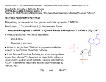
Product OverviewIdentification of Parts①②③ ④ ⑤⑥⑦①Positive Terminal (w/ Terminal Cover)⑤RS485 UP Communication Port②Negative Terminal (w/ Terminal Cover)⑥RS485 LINK Communication Port③LED Indicator⑦CAN Communication Port④Power ButtonDimensions[ 576.0mm ]22.7in05[ 200.0mm ]7.9in[ 218.9mm ]8.6in[ 415.2mm ]16.4in
[ 215.0mm ]8.5inAdditional ComponentsLong Terminal Bolts (2)The Long Terminal Bolts (M8x1x20mm) are used to secure multiple cable lugs on one batteryterminal.PreparationBefore the installation and operation of the battery, it is recommended to have the followingequipment or tools available:Proper protective equipmentInsulated tool(s)MultimeterBattery cableBattery charger / charge controllerBattery InstallationSafe and reliable installation requires trained and certified technicians. Therefore, the purposeof this section is only to serve as a guideline as all scenarios cannot be covered.06
WARNINGDO NOT short-circuit the battery terminals. Doing so can cause bursts in amperage andlead to irreversible damage to the system and the battery.Please verify the polarity before connecting wiring. Reversing polarity can and will destroythe battery.Please use circuit breakers, fuses, or disconnects appropriately sized by a certified electrician, licensed installers, or regional code authorities to protect all electrical equipment.InspectionPlease check for visible damage including cracks, dents, deformation, and other visible abnormalities. The top of the battery and terminal connections should be clean, free of dirt andcorrosion, and dry. If any problems are detected with the battery, please contact us forassistance. Refer to the last page of the manual for contact information.Cable SizingBattery cables (sold separately) should be appropriately sized to handle the expected load.Please refer to the following table for the ampacities of copper cables with different gaugesizes.Copper Cable Gauge Size (AWG/mm2)07Ampacity (A)14 (2.08)2012 (3.31)2510 (5.25)358 (8.36)506 (13.3)654 (21.1)852 (33.6)1151 (42.4)1301/0 (53.5)1502/0 (67.4)1754/0 (107)230
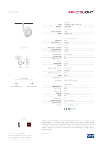
The above values are from NEC Table 310.15(B)16 for copper cables rated at 35 (167 ),operating at an ambient temperature of no more than 30 (86 ). Lengths in excess of 6 feet(1829 mm) may require heavier gauge cable to avoid unacceptable voltage drop.Connecting Batteries in BanksWARNINGDO NOT string the battery in series. Doing so can cause catastrophic failure.CAUTIONDO NOT string different types of batteries, batteries with different rated capacity, or batteries from different manufacturers in parallel.Please avoid too high a voltage difference between paralleled batteries, despite theauto-balancing function, to avoid triggering the over-current protection.In parallel battery banks, the cables between each battery should be of equal length toensure that all batteries in the system can work equally together.It is not recommended to connect more than 4 batteries in parallel if taking advantages ofthe auto-balancing function.To string multiple batteries in parallel, firstconnect the positive terminals of batteriesto each other. Then do the same with thenegative terminals. Finally, connect thepositive and negative terminals of the firstbattery to the system. This type ofarrangement is used to increase theoverall battery capacity while keeping thevoltage the same.Communication CableCopper CableTo enable the communication betweenparalleled batteries, please connect theLINK ports of former ones to the UP portsof latter ones using communicationcables (not included).08
Securing Cable ConnectionsCAUTIONPlease secure all cable connections to the proper specification in order to ensure goodcontact between the cable lugs and the terminals. Over-tightening cable connections cancause terminal breakage and loose cable connections can cause terminal meltdown or fire.Please use an insulated Philips screwdriver to tighten the cable connections.To ensure good contact between the cable lugs and the terminals, please use the appropriate number of washers to allow for as much thread engagement as possible without bottoming out the terminal bolt. The correct number of washers can be determined by hand-tightening the terminal bolt with just the cable lug in place and observing the gap that is present.Use the number of washers needed so that the washer stack is slightly larger than theobserved gap.It is very important to ensure the cable lug contacts the top surface of the terminal and thata washer is placed on top of the lug. Do not place a washer between the battery terminaland the cable lug as this can cause high resistance and cause excessive heating of theconnection.NOTEPlease use the included Long Terminal Bolts when needed to secure multiple cable lugs onone battery terminal.Installation EnvironmentThe battery should be installed in a clean, cool, and dry place, keeping water, oil, and dirtaway from the battery. The accumulation of these materials on the battery can cause currentleakage, resulting in self-discharge and a possible short-circuit. Sufficient air flow must beprovided to prevent excessive heat build-up and to minimize temperature variation betweenthe batteries.09
Battery OperationCAUTIONDO NOT over-charge or over-discharge the battery.DO NOT discharge the battery at high temperatures above 140 (60 ).Power Button OperationThe battery can be switched between active mode and shelf mode with the Power Button.When the battery is in shelf mode, long press the Power Button for 1 second to switch thebattery to active mode. The LED Indicator will illuminate after 1 2 seconds of softwareinitialization to indicate that the battery has been successfully switched to active mode. Pleasecheck the battery voltage to validate an active battery.Prior to long periods of storage, disconnect the battery from the system and longpress the Power Button for 3 seconds to switch the battery to shelf mode. The LED Indicatorwill go out t o indicate that the battery has been switched to shelf mode. In shelf mode, thebattery has a low self-discharge rate and can hold the charge for a longer period of time.CAUTIONPlease leave the battery in shelf mode during installation. DO NOT activate the battery untilmaking sure that all the connections are correct and secure. Connecting active batteries tothe system may trigger the short circuit protection of the battery.NOTEThe battery leaves the factory in shelf mode. Please switch the battery to active mode bycharging it or using the Power Button after connecting the battery to the system for the first time.Paralleled batteries can be switched to active mode simultaneously by charging them orusing the Power Button on any battery. To switch paralleled batteries to shelf mode simultaneously, please enable the communication between paralleled batteries and use the PowerButton on the first battery. Otherwise, please disconnect paralleled batteries and use thePower Button to switch each battery to shelf mode.Identifying Battery Operation StatusThe LED Indicator indicates the battery operation status. Please refer to the following tablefor more details.10
ProtectionConditionSlow Flashing GreenStandbyFast Flashing GreenNormal DischargingSolid GreenNormal Charging / Fully ChargedSolid YellowCharge Over-current Warning / Discharge Over-current WarningFlashing YellowBattery Under-voltage Warning / Battery Cell Under-voltage WarningSolid RedCharge Over-current Protection / Discharge Over-current Protection /Battery High Temperature Protection /Battery Low Temperature Protection / Short Circuit ProtectionFlashing RedBattery Under-voltage Protection /Battery Cell Under-voltage Protection /Battery Over-voltage ProtectionNOTEThe warning status will not affect the normal use of the battery. But it is recommended topay closer attention to the battery to prevent it from entering the protection mode.Self-heating Function OperationThe normal operation of the self-heating function requires a stable charge current greater than3A for each battery in the parallel battery bank. The self-heating function will start operatingautomatically once the battery and the battery temperature drops below 41 (5 ) and stopoperating automatically once the battery temperature rises above 50 (10 ).The battery leaves the factory with the self-heating function enabled. To disable the self-heating function, please switch the battery to shelf mode and long press the Power Button for 8seconds. The LED indicator will flash red, yellow, and green 3 times respectively* to indicatethat the self-heating function has been disabled. To re-enable the self-heating function, pleaserepeat the previous steps. The LED indicator will flash red, yellow, and green in sequence for3 times** to indicate that the self-heating function has been re-enabled. The battery will switchto active mode automatically after disabling or re-enabling the self-heating function. When theself-heating function is disabled, the LED indicator will flash red, yellow, and green 3 timesrespectively* every time the battery is switched to active mode.* ** CAUTIONThe self-heating function MUST be disabled or enabled uniformly on all the batteries in theparallel battery bank.11
NOTEThe self-heating function needs to be disabled or enabled individually on each battery in theparallel battery bank.The self-heating function will not be able to operate normally if a PWM charge controller ora small current battery charger is used to charge the battery at low temperatures. It isrecommended to disable the self-heating fun ction to prevent it from starting and stoppingoperation frequently and consuming the battery.Charging BatteriesCAUTIONDO NOT exceed the maximum charge current to the battery.ONLY charge the battery with a battery charger or charge controller that is compatible withlithium iron phosphate batteries.NOTEDepending on the length of time between manufacturing and shipping, the battery may bereceived at a partial state of charge. Please fully charge the battery prior to the initial use.During the standard charging process, the battery is first charged at a constant current of 10Auntil the battery voltage reaches 54V. Then, the battery is charged at a constant voltage of 54Vwhile tapering the charge current. The standard charging process is considered completewhen the charge current is less than 1A. However, leaving the battery on float will continue tobalance the battery cells and will not damage the battery. The standard charging processnormally takes 7 hours. Safe charging requires battery temperatures below 131 (55 ). If theself-heating function is disabled or unable to work normally, battery temperatures above 32(0 ) is also required for the safe charging.Discharging BatteriesCAUTIONDO NOT exceed the maximum discharge current to the battery.DO NOT connect large loads to the battery when it is running low.If the battery shuts off due to low state of charge (SoC), please disconnect the battery fromthe discharge equipment to eliminate potential parasitic loads and charge the battery assoon as possible. Failure to do so may cause irreversible damage to the battery.12
It is recommended to pair the battery with discharge equipment featuring low voltagedisconnect in the system.During the standard discharging process, the battery is discharged a constant current of 10Auntil the battery voltage reaches 41.62V. Safe discharging requires battery temperaturesbetween -4 and 140 (-20 and 60 ).Battery MaintenanceInspectionPlease perform regular visual inspections by following these steps:Examine the external appearance of the battery. The top of the battery and terminal connections should be clean, dry, and free of corrosion.Check battery cables and connections. Replace any damaged cables and tighten any looseconnections.CAUTIONTerminal corrosion may adversely affect the battery performance and present a safetyhazard. Please keep terminals free of corrosion.CleaningPlease clean the battery at regular intervals by following these steps:Disconnect the battery from the charging source or electric load.Switch the battery to shelf mode using the Power Button.Clean the top of the battery and terminals with a damp cloth or non-metallic brush. Ahousehold cleaner may be used if the battery is extremely dirty.Dry the battery with a clean cloth and keep the area around the battery clean and dry.Ensure the battery is completely dry before switching it to active mode and/or reconnectingit to the charging source or electric load.Checking VoltagePlease check the battery voltage periodically to assess battery health. If the battery restingvoltage is under 41.62V in active mode at room temperature, the battery may have beenover-discharged due to self-discharge or parasitic loads. Please stop using the battery until thefault can be corrected and the battery can be charged.13
Battery StoragePlease follow these tips to ensure that your battery emerges from storage in good condition:Charge the battery to 30% 50% and put the battery into shelf mode using the includedActivation Switch before long periods of storage.Disconnect the battery from equipment to eliminate any potential parasitic loads that maydischarge the battery.Store the battery in an open, well ventilated, dry, clean area in temperature between -13 149 (-25 65 ).Handle the battery carefully to avoid sharp impacts or extreme pressure on the batterycasing.Charge the battery at least once every 3 months to prevent over-discharge.When the battery is taken out of storage, it should be given a full charge prior to use.CAUTIONDO NOT expose the battery to the extreme temperatures over 65 (149 ).DO NOT expose the battery to heat sources.DO NOT expose the battery to direct sunlight, moisture, or precipitation.Battery Management SystemWarning and ProtectionThe battery contains a battery management system (BMS) that warns you and protects thebattery from over-voltage, under-voltage, over-current, short circuit, high temperature, and lowtemperature. Please refer to the following table for the triggering and recovery condition of eachwarning and protection.14
Battery Operation StatusBatteryOver-voltageBattery ectionWarningProtectionBattery CellUnder-voltageWarningProtectionBattery LowTemperature(Charging)Battery LowTemperature(Discharging)Battery lowTemperature(Charging)Battery ditionTriggeringRecoveryTriggeringBattery Voltage 55.5VBattery Voltage 51V / Discharge Current 1ABattery Cell Voltage 3.75VRecovery Battery Cell Voltage 3.4V / Discharge Current 1ATriggeringBattery Voltage 45.75VRecoveryBattery Voltage 50V / Charge Current 1ATriggeringBattery Voltage 41.62VRecoveryBattery Voltage 50V / Charge Current 1ATriggeringBattery Cell Voltage 3.05VRecoveryBattery Cell Voltage 3.2V /Charge Current 1ATriggeringBattery Cell Voltage 2.8VRecoveryBattery Cell Voltage 3.2V /Charge Current 1ATriggeringBattery Temperature 122 (50 )RecoveryBattery Temperature 113 (45 )TriggeringBattery Temperature 131 (55 )RecoveryBattery Temperature 122 (50 )TriggeringBattery Temperature 131 (55 )RecoveryBattery Temperature 122 (50 )TriggeringBattery Temperature 140 (60 )RecoveryBattery Temperature 131 (55 )TriggeringBattery Temperature 37.4 (3 )RecoveryBattery Temperature 42.8 (6 )TriggeringBattery Temperature 32 (0 )RecoveryBattery Temperature 37.4 (3 )TriggeringBattery Temperature 14 (-10 )RecoveryBattery Temperature 23 (-5 )TriggeringBattery Temperature -4 (-20 )RecoveryBattery Temperature 5 (-15 )
Battery Operation ryProtectionSecondaryProtectionShort CircuitProtectionConditionTriggeringCharge Current 51ARecoveryCharge Current 40ATriggeringCharge Current 55A (Delay 15s)RecoveryCharge Current 40A (Delay 1min) /Discharge Current 1ATriggeringCharge Current 120ARecoveryCharge Current 40A (Delay 1min) /Discharge Current 1ATriggeringDischarge Current 51ARecoveryDischarge Current 45ATriggeringDischarge Current 55A (Delay 15s)RecoveryDischarge Current 40A (Delay 1min) /Charge Current 1ATriggeringDischarge Current 120ARecoveryDischarge Current 40A (Delay 1min) /Charge Current 1ATriggeringDischarge Current 400A (Delay 300μs)RecoveryRemove Short Circuits /Charge Current 1ABattery Cell BalancingThe battery employs bypass circuit to maintain the balance between each battery cell group.Each battery cell group is connected with a bypass resistor and a switch in parallel. During thecharging process, if the highest-voltage battery cell group reaches the set balancing startingvoltage and the voltage difference between the highest-voltage and the lowest-voltage batterycell group exceeds the set voltage difference, the switch connected to the highest-voltagebattery cell group will be closed to shunt the charge current around the highest-voltage batterycell group through the bypass resistor until the voltage difference drops below the set value. Toavoid excessive energy loss, the battery cell balancing is only performed during the chargingprocess.16
TroubleshootingIf any problems occur during battery operation, please refer to the following instructions orcontact us for assistance:If the Power Button is not able to switch the battery to active mode or the battery restingvoltage is under 41.62V in active mode at room temperature, the battery may have beenseverely over-discharged due to self-discharge or parasitic loads. Please revive the batteryusing a battery charger or charge controller with the lithium battery activation function.If the battery terminal voltage shows 0V in active mode, the battery internal fuses may haveblown due to severe over-current. Please contact us for assistance.If the battery voltage gets too low to reliably power electric loads or triggers the batteryunder-voltage protection, please disconnect the battery from electric loads and charge thebattery as soon as possible.If the battery temperature gets too high/low during the operation and triggers the batteryhigh/low temperature protection, please disconnect the battery from the charging sourceand electric loads and cool down/warm up the battery to room temperature. The battery willautomatically recover from the battery high/low temperature protection.If too high a current passes through the battery and triggers the charge/discharge over-current protection, please disconnect the battery from the charging source/electric loadimmediately. The battery will automatically recover from the charge/discharge over-currentprotection after 1 minute. If the charge/discharge over-current protection is triggered 3 timesin a row, the battery will no longer recover automatically. Please discharge/charge thebattery with a current greater than 1A to recover the battery from the charge/dischargeover-current protection.If the battery is short circuited and triggers the short circuit protection, please remove theshort circuit immediately and charge the battery with a current greater than 1A to recover thebattery from the short circuit protection.17
SpecificationsGeneralCell TypeLiFePO4Rated Capacity (0.2C)50AhNominal Voltage48VVoltage Range142V 55.5VCycle Life (0.2C, 25 )4500 Cycles (80% DOD)Insulation Resistance 20mΩDimension22.7 x 8.5 x 7.9 inch /576 x 215 x 200 mmWeight60.8 lb. / 27.6 kgCommunication PortRJ45 (RS485 Protocol, CAN Protocol)Connection MethodParallelTerminal Bolt SizeM8 x 1 x 15 mmRecommended Terminal Torque62.0-70.8 inch·lb / 7-8 N·mCertificationsUN38.3, MSDS, UL1642 (Battery Cell)Operation ParametersCharging Voltage54VMaximum Continuous Charging Current50AStandard Operation Temperature77 9 (25 5 )Charging Temperature Range32 131 / 0 55 Discharging Temperature Range-4 140 / -20 60 Storage Temperature Range-13 149 / -25 65 Relative Humidity5%-95%18
RENOGY.COMRenogy reserves the right to changethe contents of this manual without notice.US2775 E Philadelphia St, Ontario, CA 91761, @renogy.cn
Button on the first battery. Otherwise, please disconnect paralleled batteries and use the Power Button to switch each battery to shelf mode. The battery can be switched between active mode and shelf mode with the Power Button. When the battery is in shelf mode, long press the Power Button for 1 second to switch the battery to active mode.