Transcription
INSTALLATIONMANUALR410A SPLIT SERIESInstallation ManualE nglis hR410A Split SeriesManuale d’installazioneI talianoSerie Multiambienti R410AInstallationsanleitungDeutschSplit-Baureihe R410AManual de instalaciónE spa ñolSerie Split R410AManuel d’installationFr ançai sSérie split R410AMontaj kýlavuzlarýTür kçeR410A Split serisiРуководство по монтажуР усскийСерия R410A с раздельной 1BIM-5WMYJ-0811(4)-DAIKINPart Number: R08019036974D
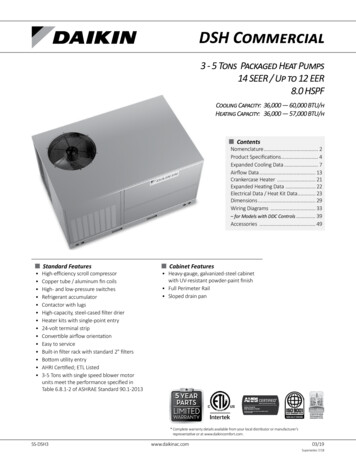
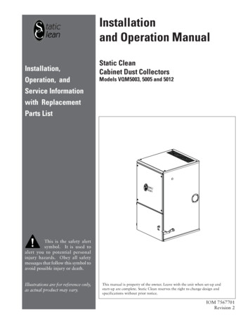
OUTLINE AND DIMENSIONSTHE MARK()E ngn g llisishIndoor UnitSHOWS PIPING DIRECTIONREAROriginal InstructionAREARLEFTRIGHTCTOP VIEWBBOTTOMTERMINALBLOCKWITH EARTHTERMINALINDOOR UNITON/OFF SWITCHBOTTOMLOUVERBNAME PLATESIGNAL RECEIVERSIDE VIEWROOM TEMPERATURETHERMISTOR (INSIDE)FRONT GRILLE FIXEDSCREWS (INSIDE)FRONT VIEWUse tape measureas shown.Position the endof a tape measureat uRecommended mountingplate retention spots(5 spots in all)EFDBFThrough the wallhole Ø 65mmGGJLHKMALiquid pipe endIDrain hosepositionGas pipe endINSTALLATION PLATE FTXN25/35LV1B1-1All dimensions are in mm
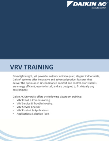
Recommended mounting plateretention spots (7 spots in all)Through the wallhole Ø 65mmLiquid pipe endDrain hosepositionGas pipe endINSTALLATION PLATE FTXN50/60LV1BDimensionAll dimensions are in 121958045ModelOutdoor Unit [RXN25/35LV1B]All dimensions are in JKLMN55065851112731614470962999460141331-2
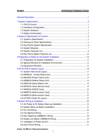
Outdoor Unit [RXN50/60LV1B]E ngn g llisishAll dimensions are in 2616415OPQRS342336273751-3
INSTALLATION MANUALThis manual provides the procedures of installation to ensure a safe and good standard of operation for the air conditioner unit.Special adjustment may be necessary to suit local requirements.Before using your air conditioner, please read this instruction manual carefully and keep it for future reference.This appliance is intended to be used by expert or trained users in shops, in light industry and on farms, or for commercial use bylay persons.This appliance is not intended for use by persons, including children, with reduced physical, sensory or mental capabilities, or lackof experience and knowledge, unless they have been given supervision or instruction concerning use of the appliance by a personresponsible for their safety.Children should be supervised to ensure that they do not play with the appliance.SAFETY PRECAUTIONSCAUTIONWARNINGPlease take note of the following important pointswhen installing. Do not install the unit where leakage of flammablegas may occur.If gas leaks and accumulates around the unit, itmay cause fire ignition. Ensure that drainage piping is connected properly.If the drainage piping is not connected properly, itmay cause water leakage which will dampen thefurniture. Do not overcharge the unit.This unit is factory pre-charged. Overcharge willcause over-current or damage to the compressor. Ensure that the unit’s panel is closed after service orinstallation.Unsecured panels will cause the unit to operatenoisily. Sharp edges and coil surfaces are potential locationswhich may cause injury hazards. Avoid from being incontact with these places. Before turning off the power supply, set the remotecontroller’s ON/OFF switch to the “OFF” position toprevent the nuisance tripping of the unit. If this is notdone, the unit’s fans will start turning automatically whenpower resumes, posing a hazard to service personnel orthe user. Do not install the units at or near doorway. Do not operate any heating apparatus too close to theair conditioner unit or use in room where mineral oil, oilvapour or oil steam exist, this may cause plastic part tomelt or deform as a result of excessive heat or chemicalreaction. When the unit is used in kitchen, keep flour away fromgoing into suction of the unit. This unit is not suitable for factory used where cutting oilmist or iron powder exist or voltage fluctuates greatly. Do not install the units at area like hot spring or oilrefinery plant where sulphide gas exists. Ensure the color of wires of the outdoor unit and theterminal markings are same to the indoors respectively. IMPORTANT : DO NOT INSTALL OR USE THE AIRCONDITIONER UNIT IN A LAUNDRY ROOM. Do not use joined and twisted wires for incoming powersupply. For any enquiries on spare part, please contact yourauthorized dealer. The equipment is not intended for use in a potentiallyexplosive atmosphere. Installation and maintenance should be performed byqualified persons who are familiar with local code andregulation, and experienced with this type of appliance. All field wiring must be installed in accordance with thenational wiring regulation. Ensure that the rated voltage of the unit corresponds tothat of the name plate before commencing wiring workaccording to the wiring diagram. The unit must be GROUNDED to prevent possible hazarddue to insulation failure. All electrical wiring must not touch the refrigerant pipingor any moving parts of the fan motors. Confirm that the unit has been switched OFF beforeinstalling or servicing the unit. Disconnect from the main power supply before servicingthe air conditioner unit. DO NOT pull out the power cord when the power is ON.This may cause serious electrical shocks which mayresult in fire hazards. Keep the indoor and outdoor units, power cable andtransmission wiring, at least 1m from TVs and radios, toprevent distorted pictures and static. {Depending on thetype and source of the electrical waves, static may beheard even when more than 1m away}.NOTICEDisposal requirementsYour air conditioning product is marked with this symbol. This means that electrical and electronic products shall notbe mixed with unsorted household waste.Do not try to dismantle the system yourself: the dismantling of the air conditioning system, treatment of the refrigerant,of oil and of other parts must be done by a qualified installer in accordance with relevant local and national legislation.Air conditioners must be treated at a specialized treatment facility for re-use, recycling and recovery. By ensuring thisproduct is disposed of correctly, you will help to prevent potential negative consequences for the environment andhuman health. Please contact the installer or local authority for more information.Batteries must be removed from the remote controller and disposed of separately in accordance with relevant localand national legislation.1-4
Important information regarding the refrigerant usedThis product contains fluorinated greenhouse gases covered by the Kyoto Protocol.Do not vent gases into the atmosphere.Refrigerant type: R410A1975GWP(1) value:(1)GWP global warming potentialPlease fill in with indelible ink,! A the factory refrigerant charge of the product,! B the additional refrigerant amount charged in the field and! A B the total refrigerant chargeon the refrigerant charge label supplied with the product.The filled out label must be adhered in the proximity of the product charging port (e.g. onto the inside of the servicecover).1 factory refrigerant charge of the product:see unit name plate(2)2 additional refrigerant amount charged in the field3 total refrigerant charge4 contains fluorinated greenhouse gases covered by the Kyoto Protocol5 outdoor unit6 refrigerant cylinder and manifold for chargingIn case of multiple indoor systems, only 1 label must be adhered*, mentioning the total factory refrigerant charge ofall indoor units connected in the refrigerant system.Periodical inspections for refrigerant leaks may be required depending on European or local legislation. Pleasecontact your local dealer for more information.* on the outdoor unit(2)1-5E ngn g llisishIMPORTANT
INSTALLATION DIAGRAMIndoor Unit30mm or more from ceilingCaulk pipehole gapwith putty.Front PanelCut thermal insulation pipe toan appropriate length and wrapit with tape, making sure that nogap is left in the insulation pipe’scut line.Wrap the insulation pipe with thefinishing tape from bottom to top.50mm or more from walls(on both sides)M4 X 12LAir filterService lid Opening service lidService lid is opening/closingtype. Opening method1) Remove the service lidscrews.2) Pull out the service liddiagonally down in the directionof the arrow.3) Pull down.Outdoor Unit250mm fromwallINSTALLATION OF THE OUTDOOR UNIT (RXN25/35LV1B) Where a wall or other obstacle is in the path of outdoor unit’s intake or exhaust airflow, follow the installation guidelines below. For any of the below installation patterns, the wall height on the exhaust side should be 1200mm or less.Wall facing one sideMore than 50Walls facing two sidesMore than 100More than 150More than1001200or lessMore than 50More than 50Top viewSide viewWalls facing three sidesMore than 150More than 50More than 300Top viewunit: mm1-6
1) Use drain plug for drainage.2) If the drain port is covered by a mounting base or floor surface, placeadditional foot bases of at least 30mm in height under the outdoor unit’sfeet.3) In cold areas, do not use a drain hose with the outdoor unit.(Otherwise, drain water may freeze, impairing heating performance.)E ngn g llisishDrain work. (Heat Pump Unit Only)Drain water holeBottom frameDrain plugHose (available commercially,inner dia. 16mm)INSTALLATION OF THE OUTDOOR UNIT (RXN50/60LV1B)BDischarge airReturn airObstacleAObstacleThe outdoor unit must be installed in such a way, soas to prevent short circuit of the hot discharged air orobstruction to the smooth air flow. Please follow theinstallation clearances shown in the figure. Select thecoolest possible place where intake air temperature isnot greater than the outside air temperature (Refer tooperating range).Installation clearancesMinimum Distance, mmABCD3001000300500CService accessCondensed Water Disposal Of Outdoor Unit(Heat Pump Unit Only) There are 2 holes on the base of Outdoor Unit forcondensed water to flow out. Insert the drain elbow toone of the holes. To install the drain elbow, first insert one portion of thehook to the base (portion A), then pull the drain elbowin the direction shown by the arrow while inserting theother portion to the base. After installation, check toensure that the drain elbow clings to base firmly. If the unit is installed in a snowy and chilly area,condensed water may freeze in the base. In suchcase, please remove plug at the bottom of unit tosmooth the drainage.Return airObstacleNote: If there is any obstacle higher than 2m, or if thereis any obstruction at the upper part of the unit, pleaseallow more space than the figure indicated in the abovetable.DObstacleDimensionPLUGABASEDRAIN ELBOWDRAINELBOWPlease removeside plate whenconnecting the pipingand connecting cordPUSH & PULL UP1-7
INSTALLATION OF THE INDOOR UNITThe indoor unit must be installed in such a way so as toprevent short circuit of the cool discharged air with the hotreturn air. Please follow the installation clearance shownin the figure. Do not place the indoor unit where therecould be direct sunlight shining on it. Also, this locationmust be suitable for piping and drainage, and be awayfrom doors or windows.The refrigerant piping can be routed to the unit in anumber of ways (left or right from the back of the unit), byusing the cut-out holes on the casing of the unit.Bend the pipes carefully to the required position in orderto align it with the holes. For the side and bottom out,hold the bottom of the piping and then position it to therequired direction. The condensation drain hose can betaped to the pipes.min. 30(Space forperformance)Right-side, right-back or right-bottom pipingAir flow(Indoor)Right-sidepipingmin. 50(Space formaintenance)min. 50Required spaceRight-back pipingRemove pipe port coverhere for right-side piping(Space formaintenance)Right-bottompipingAll dimensions are in mmRemove pipe port coverhere for right-bottom pipingBind coolant pipe anddrain hose togetherwith insulating tape.Left-side, left-back or left-bottom pipingRemove pipe port coverhere for left-side pipingLeft-side pipingRemove pipe port cover here for left-bottompipingLeft-bottom piping1-8Left-back piping
Mounting Installation PlateHole with cone drillFTXN25/35LV1BMounting plateInsideOutsideWall embedded pipe(Field supply)CaulkingE ngn g llisishEnsure that the wall is strong enough to withstand theweight of the unit. Otherwise, it is necessary to reinforcethe wall with plates, beams or pillars.Use the level gauge for horizontal mounting, and fix it with5 suitable screws for FTXN25/35LV1B and 7 suitablescrews for FTXN50/60LV1B.In case the rear piping draws out, drill a hole 65mm indiameter with a cone drill, slightly lower on the outsidewall (see figure).Ø 65Wall hole cover(Field supply)Wall embedded pipe(Field supply)Mount The Unit Onto The Installation PlateHook the indoor unit onto the upper portion of theinstallation plate (Engage the two hooks at the rear topof the indoor unit with the upper edge of the installationplate). Ensure that the hooks are properly seated on theinstallation plate by moving it to the left and right.How To Attach The Indoor UnitHook the claws of the bottom frame to the mountingplate.How To Remove The Indoor UnitPush up the marked area (at the lower part of the frontgrille) to release the claws.Mounting platefixing screwMounting plateFTXN50/60LV1BMounting plateClipBottom frameMounting platefixing screwMark (Rear side)Front grilleHand indoor unit’s hook here.Recommended Mounting Plate Retention Spots AndDimensionsMounting plateWhen stripping the endsof interconnecting wires inadvance, bind right endsof wires with insulatingtape.FTXN25/35LV1BUse tape measure as shown.Position the end of a tapemeasure at uRecommended mounting plateretention spots (5 spots in all)166Interconnectingwires18442 242 2Wire guideWater Draina
J G G L D B K M A F THE MARK ( ) SHOWS PIPING DIRECTION Use tape measure as shown. Position the end of a tape measure at u Recommended mounting plate retention spots (5 spots in all) Liquid pipe end Gas pipe end INSTALLATION PLATE FTXN25/35LV1B All dimensions are in mm Through the wall hole Ø 65mm Drain hose position Original Instruction A B C B REAR REAR LEFT RIGHT TOP VIEW